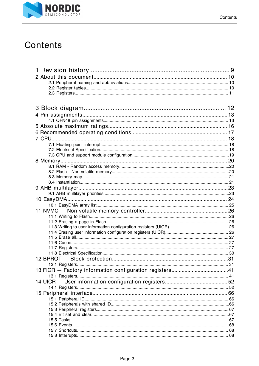
Contents
1 Revision history
2 About this document
2.1 Peripheral naming and abbreviations
2.2 Register tables
2.2.1 Fields and values
2.3 Registers
2.3.1 DUMMY
3 Block diagram
4 Pin assignments
4.1 QFN48 pin assignments
5 Absolute maximum ratings
6 Recommended operating conditions
7 CPU
7.1 Floating point interrupt
7.2 Electrical Specification
7.2.1 CPU performance
7.3 CPU and support module configuration
8 Memory
8.1 RAM - Random access memory
8.2 Flash - Non-volatile memory
8.3 Memory map
8.4 Instantiation
9 AHB multilayer
9.1 AHB multilayer priorities
10 EasyDMA
10.1 EasyDMA array list
11 NVMC — Non-volatile memory controller
11.1 Writing to Flash
11.2 Erasing a page in Flash
11.3 Writing to user information configuration registers (UICR)
11.4 Erasing user information configuration registers (UICR)
11.5 Erase all
11.6 Cache
11.7 Registers
11.7.1 READY
11.7.2 CONFIG
11.7.3 ERASEPAGE
11.7.4 ERASEPCR1 ( Deprecated )
11.7.5 ERASEALL
11.7.6 ERASEPCR0 ( Deprecated )
11.7.7 ERASEUICR
11.7.8 ICACHECNF
11.7.9 IHIT
11.7.10 IMISS
11.8 Electrical Specification
11.8.1 Flash programming
11.8.2 Cache size
12 BPROT — Block protection
12.1 Registers
12.1.1 CONFIG0
12.1.2 CONFIG1
12.1.3 DISABLEINDEBUG
12.1.4 CONFIG2
12.1.5 CONFIG3
13 FICR — Factory information configuration registers
13.1 Registers
13.1.1 CODEPAGESIZE
13.1.2 CODESIZE
13.1.3 DEVICEID[0]
13.1.4 DEVICEID[1]
13.1.5 ER[0]
13.1.6 ER[1]
13.1.7 ER[2]
13.1.8 ER[3]
13.1.9 IR[0]
13.1.10 IR[1]
13.1.11 IR[2]
13.1.12 IR[3]
13.1.13 DEVICEADDRTYPE
13.1.14 DEVICEADDR[0]
13.1.15 DEVICEADDR[1]
13.1.16 INFO.PART
13.1.17 INFO.VARIANT
13.1.18 INFO.PACKAGE
13.1.19 INFO.RAM
13.1.20 INFO.FLASH
13.1.21 TEMP.A0
13.1.22 TEMP.A1
13.1.23 TEMP.A2
13.1.24 TEMP.A3
13.1.25 TEMP.A4
13.1.26 TEMP.A5
13.1.27 TEMP.B0
13.1.28 TEMP.B1
13.1.29 TEMP.B2
13.1.30 TEMP.B3
13.1.31 TEMP.B4
13.1.32 TEMP.B5
13.1.33 TEMP.T0
13.1.34 TEMP.T1
13.1.35 TEMP.T2
13.1.36 TEMP.T3
13.1.37 TEMP.T4
13.1.38 NFC.TAGHEADER0
13.1.39 NFC.TAGHEADER1
13.1.40 NFC.TAGHEADER2
13.1.41 NFC.TAGHEADER3
14 UICR — User information configuration registers
14.1 Registers
14.1.1 NRFFW[0]
14.1.2 NRFFW[1]
14.1.3 NRFFW[2]
14.1.4 NRFFW[3]
14.1.5 NRFFW[4]
14.1.6 NRFFW[5]
14.1.7 NRFFW[6]
14.1.8 NRFFW[7]
14.1.9 NRFFW[8]
14.1.10 NRFFW[9]
14.1.11 NRFFW[10]
14.1.12 NRFFW[11]
14.1.13 NRFFW[12]
14.1.14 NRFFW[13]
14.1.15 NRFFW[14]
14.1.16 NRFHW[0]
14.1.17 NRFHW[1]
14.1.18 NRFHW[2]
14.1.19 NRFHW[3]
14.1.20 NRFHW[4]
14.1.21 NRFHW[5]
14.1.22 NRFHW[6]
14.1.23 NRFHW[7]
14.1.24 NRFHW[8]
14.1.25 NRFHW[9]
14.1.26 NRFHW[10]
14.1.27 NRFHW[11]
14.1.28 CUSTOMER[0]
14.1.29 CUSTOMER[1]
14.1.30 CUSTOMER[2]
14.1.31 CUSTOMER[3]
14.1.32 CUSTOMER[4]
14.1.33 CUSTOMER[5]
14.1.34 CUSTOMER[6]
14.1.35 CUSTOMER[7]
14.1.36 CUSTOMER[8]
14.1.37 CUSTOMER[9]
14.1.38 CUSTOMER[10]
14.1.39 CUSTOMER[11]
14.1.40 CUSTOMER[12]
14.1.41 CUSTOMER[13]
14.1.42 CUSTOMER[14]
14.1.43 CUSTOMER[15]
14.1.44 CUSTOMER[16]
14.1.45 CUSTOMER[17]
14.1.46 CUSTOMER[18]
14.1.47 CUSTOMER[19]
14.1.48 CUSTOMER[20]
14.1.49 CUSTOMER[21]
14.1.50 CUSTOMER[22]
14.1.51 CUSTOMER[23]
14.1.52 CUSTOMER[24]
14.1.53 CUSTOMER[25]
14.1.54 CUSTOMER[26]
14.1.55 CUSTOMER[27]
14.1.56 CUSTOMER[28]
14.1.57 CUSTOMER[29]
14.1.58 CUSTOMER[30]
14.1.59 CUSTOMER[31]
14.1.60 PSELRESET[0]
14.1.61 PSELRESET[1]
14.1.62 APPROTECT
14.1.63 NFCPINS
15 Peripheral interface
15.1 Peripheral ID
15.2 Peripherals with shared ID
15.3 Peripheral registers
15.4 Bit set and clear
15.5 Tasks
15.6 Events
15.7 Shortcuts
15.8 Interrupts
15.8.1 Interrupt clearing
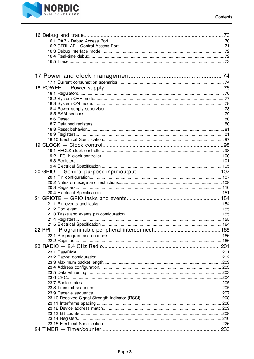
16 Debug and trace
16.1 DAP - Debug Access Port
16.2 CTRL-AP - Control Access Port
16.2.1 Registers
RESET
ERASEALL
ERASEALLSTATUS
APPROTECTSTATUS
IDR
16.3 Debug interface mode
16.4 Real-time debug
16.5 Trace
16.5.1 Electrical Specification
Trace port
17 Power and clock management
17.1 Current consumption scenarios
17.1.1 Electrical Specification
Current consumption: Radio
Current consumption: Radio protocol configurations
Current consumption: Ultra-low power
18 POWER — Power supply
18.1 Regulators
18.2 System OFF mode
18.2.1 Emulated System OFF mode
18.3 System ON mode
18.3.1 Sub power modes
18.4 Power supply supervisor
18.4.1 Power-fail comparator
18.5 RAM sections
18.6 Reset
18.6.1 Power-on reset
18.6.2 Pin reset
18.6.3 Wakeup from System OFF mode reset
18.6.4 Soft reset
18.6.5 Watchdog reset
18.6.6 Brown-out reset
18.7 Retained registers
18.8 Reset behavior
18.9 Registers
18.9.1 INTENSET
18.9.2 INTENCLR
18.9.3 RESETREAS
18.9.4 RAMSTATUS ( Deprecated )
18.9.5 SYSTEMOFF
18.9.6 POFCON
18.9.7 GPREGRET
18.9.8 GPREGRET2
18.9.9 RAMON ( Deprecated )
18.9.10 RAMONB ( Deprecated )
18.9.11 DCDCEN
18.9.12 RAM[0].POWER
18.9.13 RAM[0].POWERSET
18.9.14 RAM[0].POWERCLR
18.9.15 RAM[1].POWER
18.9.16 RAM[1].POWERSET
18.9.17 RAM[1].POWERCLR
18.9.18 RAM[2].POWER
18.9.19 RAM[2].POWERSET
18.9.20 RAM[2].POWERCLR
18.9.21 RAM[3].POWER
18.9.22 RAM[3].POWERSET
18.9.23 RAM[3].POWERCLR
18.9.24 RAM[4].POWER
18.9.25 RAM[4].POWERSET
18.9.26 RAM[4].POWERCLR
18.9.27 RAM[5].POWER
18.9.28 RAM[5].POWERSET
18.9.29 RAM[5].POWERCLR
18.9.30 RAM[6].POWER
18.9.31 RAM[6].POWERSET
18.9.32 RAM[6].POWERCLR
18.9.33 RAM[7].POWER
18.9.34 RAM[7].POWERSET
18.9.35 RAM[7].POWERCLR
18.10 Electrical Specification
18.10.1 Current consumption, sleep
18.10.2 Device startup times
18.10.3 Power fail comparator
19 CLOCK — Clock control
19.1 HFCLK clock controller
19.1.1 64 MHz crystal oscillator (HFXO)
19.2 LFCLK clock controller
19.2.1 32.768 kHz RC oscillator (LFRC)
19.2.2 Calibrating the 32.768 kHz RC oscillator
19.2.3 Calibration timer
19.2.4 32.768 kHz crystal oscillator (LFXO)
19.2.5 32.768 kHz synthesized from HFCLK (LFSYNT)
19.3 Registers
19.3.1 INTENSET
19.3.2 INTENCLR
19.3.3 HFCLKRUN
19.3.4 HFCLKSTAT
19.3.5 LFCLKRUN
19.3.6 LFCLKSTAT
19.3.7 LFCLKSRCCOPY
19.3.8 LFCLKSRC
19.3.9 CTIV
19.3.10 TRACECONFIG
19.4 Electrical Specification
19.4.1 64 MHz internal oscillator (HFINT)
19.4.2 64 MHz crystal oscillator (HFXO)
19.4.3 Low frequency crystal oscillator (LFXO)
19.4.4 Low frequency RC oscillator (LFRC)
19.4.5 Synthesized low frequency clock (LFSYNT)
20 GPIO — General purpose input/output
20.1 Pin configuration
20.2 Notes on usage and restrictions
20.2.1 GPIO located near the radio
20.2.2 NFC antenna pins
20.3 Registers
20.3.1 OUT
20.3.2 OUTSET
20.3.3 OUTCLR
20.3.4 IN
20.3.5 DIR
20.3.6 DIRSET
20.3.7 DIRCLR
20.3.8 LATCH
20.3.9 DETECTMODE
20.3.10 PIN_CNF[0]
20.3.11 PIN_CNF[1]
20.3.12 PIN_CNF[2]
20.3.13 PIN_CNF[3]
20.3.14 PIN_CNF[4]
20.3.15 PIN_CNF[5]
20.3.16 PIN_CNF[6]
20.3.17 PIN_CNF[7]
20.3.18 PIN_CNF[8]
20.3.19 PIN_CNF[9]
20.3.20 PIN_CNF[10]
20.3.21 PIN_CNF[11]
20.3.22 PIN_CNF[12]
20.3.23 PIN_CNF[13]
20.3.24 PIN_CNF[14]
20.3.25 PIN_CNF[15]
20.3.26 PIN_CNF[16]
20.3.27 PIN_CNF[17]
20.3.28 PIN_CNF[18]
20.3.29 PIN_CNF[19]
20.3.30 PIN_CNF[20]
20.3.31 PIN_CNF[21]
20.3.32 PIN_CNF[22]
20.3.33 PIN_CNF[23]
20.3.34 PIN_CNF[24]
20.3.35 PIN_CNF[25]
20.3.36 PIN_CNF[26]
20.3.37 PIN_CNF[27]
20.3.38 PIN_CNF[28]
20.3.39 PIN_CNF[29]
20.3.40 PIN_CNF[30]
20.3.41 PIN_CNF[31]
20.4 Electrical Specification
20.4.1 GPIO Electrical Specification
21 GPIOTE — GPIO tasks and events
21.1 Pin events and tasks
21.2 Port event
21.3 Tasks and events pin configuration
21.4 Registers
21.4.1 INTENSET
21.4.2 INTENCLR
21.4.3 CONFIG[0]
21.4.4 CONFIG[1]
21.4.5 CONFIG[2]
21.4.6 CONFIG[3]
21.4.7 CONFIG[4]
21.4.8 CONFIG[5]
21.4.9 CONFIG[6]
21.4.10 CONFIG[7]
21.5 Electrical Specification
21.5.1 GPIOTE Electrical Specification
22 PPI — Programmable peripheral interconnect
22.1 Pre-programmed channels
22.2 Registers
22.2.1 CHEN
22.2.2 CHENSET
22.2.3 CHENCLR
22.2.4 CH[0].EEP
22.2.5 CH[0].TEP
22.2.6 CH[1].EEP
22.2.7 CH[1].TEP
22.2.8 CH[2].EEP
22.2.9 CH[2].TEP
22.2.10 CH[3].EEP
22.2.11 CH[3].TEP
22.2.12 CH[4].EEP
22.2.13 CH[4].TEP
22.2.14 CH[5].EEP
22.2.15 CH[5].TEP
22.2.16 CH[6].EEP
22.2.17 CH[6].TEP
22.2.18 CH[7].EEP
22.2.19 CH[7].TEP
22.2.20 CH[8].EEP
22.2.21 CH[8].TEP
22.2.22 CH[9].EEP
22.2.23 CH[9].TEP
22.2.24 CH[10].EEP
22.2.25 CH[10].TEP
22.2.26 CH[11].EEP
22.2.27 CH[11].TEP
22.2.28 CH[12].EEP
22.2.29 CH[12].TEP
22.2.30 CH[13].EEP
22.2.31 CH[13].TEP
22.2.32 CH[14].EEP
22.2.33 CH[14].TEP
22.2.34 CH[15].EEP
22.2.35 CH[15].TEP
22.2.36 CH[16].EEP
22.2.37 CH[16].TEP
22.2.38 CH[17].EEP
22.2.39 CH[17].TEP
22.2.40 CH[18].EEP
22.2.41 CH[18].TEP
22.2.42 CH[19].EEP
22.2.43 CH[19].TEP
22.2.44 CHG[0]
22.2.45 CHG[1]
22.2.46 CHG[2]
22.2.47 CHG[3]
22.2.48 CHG[4]
22.2.49 CHG[5]
22.2.50 FORK[0].TEP
22.2.51 FORK[1].TEP
22.2.52 FORK[2].TEP
22.2.53 FORK[3].TEP
22.2.54 FORK[4].TEP
22.2.55 FORK[5].TEP
22.2.56 FORK[6].TEP
22.2.57 FORK[7].TEP
22.2.58 FORK[8].TEP
22.2.59 FORK[9].TEP
22.2.60 FORK[10].TEP
22.2.61 FORK[11].TEP
22.2.62 FORK[12].TEP
22.2.63 FORK[13].TEP
22.2.64 FORK[14].TEP
22.2.65 FORK[15].TEP
22.2.66 FORK[16].TEP
22.2.67 FORK[17].TEP
22.2.68 FORK[18].TEP
22.2.69 FORK[19].TEP
22.2.70 FORK[20].TEP
22.2.71 FORK[21].TEP
22.2.72 FORK[22].TEP
22.2.73 FORK[23].TEP
22.2.74 FORK[24].TEP
22.2.75 FORK[25].TEP
22.2.76 FORK[26].TEP
22.2.77 FORK[27].TEP
22.2.78 FORK[28].TEP
22.2.79 FORK[29].TEP
22.2.80 FORK[30].TEP
22.2.81 FORK[31].TEP
23 RADIO — 2.4 GHz Radio
23.1 EasyDMA
23.2 Packet configuration
23.3 Maximum packet length
23.4 Address configuration
23.5 Data whitening
23.6 CRC
23.7 Radio states
23.8 Transmit sequence
23.9 Receive sequence
23.10 Received Signal Strength Indicator (RSSI)
23.11 Interframe spacing
23.12 Device address match
23.13 Bit counter
23.14 Registers
23.14.1 SHORTS
23.14.2 INTENSET
23.14.3 INTENCLR
23.14.4 CRCSTATUS
23.14.5 RXMATCH
23.14.6 RXCRC
23.14.7 DAI
23.14.8 PACKETPTR
23.14.9 FREQUENCY
23.14.10 TXPOWER
23.14.11 MODE
23.14.12 PCNF0
23.14.13 PCNF1
23.14.14 BASE0
23.14.15 BASE1
23.14.16 PREFIX0
23.14.17 PREFIX1
23.14.18 TXADDRESS
23.14.19 RXADDRESSES
23.14.20 CRCCNF
23.14.21 CRCPOLY
23.14.22 CRCINIT
23.14.23 TIFS
23.14.24 RSSISAMPLE
23.14.25 STATE
23.14.26 DATAWHITEIV
23.14.27 BCC
23.14.28 DAB[0]
23.14.29 DAB[1]
23.14.30 DAB[2]
23.14.31 DAB[3]
23.14.32 DAB[4]
23.14.33 DAB[5]
23.14.34 DAB[6]
23.14.35 DAB[7]
23.14.36 DAP[0]
23.14.37 DAP[1]
23.14.38 DAP[2]
23.14.39 DAP[3]
23.14.40 DAP[4]
23.14.41 DAP[5]
23.14.42 DAP[6]
23.14.43 DAP[7]
23.14.44 DACNF
23.14.45 MODECNF0
23.14.46 POWER
23.15 Electrical Specification
23.15.1 General Radio Characteristics
23.15.2 Radio current consumption (Transmitter)
23.15.3 Radio current consumption (Receiver)
23.15.4 Transmitter specification
23.15.5 Receiver operation
23.15.6 RX selectivity
23.15.7 RX intermodulation
23.15.8 Radio timing
23.15.9 Received Signal Strength Indicator (RSSI) specifications
23.15.10 Jitter
23.15.11 Delay when disabling the RADIO
24 TIMER — Timer/counter
24.1 Capture
24.2 Compare
24.3 Task delays
24.4 Task priority
24.5 Registers
24.5.1 SHORTS
24.5.2 INTENSET
24.5.3 INTENCLR
24.5.4 MODE
24.5.5 BITMODE
24.5.6 PRESCALER
24.5.7 CC[0]
24.5.8 CC[1]
24.5.9 CC[2]
24.5.10 CC[3]
24.5.11 CC[4]
24.5.12 CC[5]
24.6 Electrical Specification
24.6.1 Timers Electrical Specification
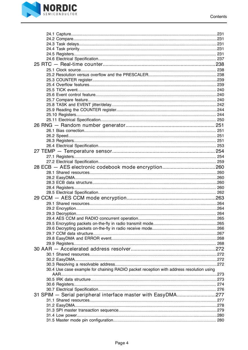
25 RTC — Real-time counter
25.1 Clock source
25.2 Resolution versus overflow and the PRESCALER
25.3 COUNTER register
25.4 Overflow features
25.5 TICK event
25.6 Event control feature
25.7 Compare feature
25.8 TASK and EVENT jitter/delay
25.9 Reading the COUNTER register
25.10 Registers
25.10.1 INTENSET
25.10.2 INTENCLR
25.10.3 EVTEN
25.10.4 EVTENSET
25.10.5 EVTENCLR
25.10.6 COUNTER
25.10.7 PRESCALER
25.10.8 CC[0]
25.10.9 CC[1]
25.10.10 CC[2]
25.10.11 CC[3]
25.11 Electrical Specification
25.11.1 RTC Electrical Specification
26 RNG — Random number generator
26.1 Bias correction
26.2 Speed
26.3 Registers
26.3.1 SHORTS
26.3.2 INTENSET
26.3.3 INTENCLR
26.3.4 CONFIG
26.3.5 VALUE
26.4 Electrical Specification
26.4.1 RNG Electrical Specification
27 TEMP — Temperature sensor
27.1 Registers
27.1.1 INTENSET
27.1.2 INTENCLR
27.1.3 TEMP
27.1.4 A0
27.1.5 A1
27.1.6 A2
27.1.7 A3
27.1.8 A4
27.1.9 A5
27.1.10 B0
27.1.11 B1
27.1.12 B2
27.1.13 B3
27.1.14 B4
27.1.15 B5
27.1.16 T0
27.1.17 T1
27.1.18 T2
27.1.19 T3
27.1.20 T4
27.2 Electrical Specification
27.2.1 Temperature Sensor Electrical Specification
28 ECB — AES electronic codebook mode encryption
28.1 Shared resources
28.2 EasyDMA
28.3 ECB data structure
28.4 Registers
28.4.1 INTENSET
28.4.2 INTENCLR
28.4.3 ECBDATAPTR
28.5 Electrical Specification
28.5.1 ECB Electrical Specification
29 CCM — AES CCM mode encryption
29.1 Shared resources
29.2 Encryption
29.3 Decryption
29.4 AES CCM and RADIO concurrent operation
29.5 Encrypting packets on-the-fly in radio transmit mode
29.6 Decrypting packets on-the-fly in radio receive mode
29.7 CCM data structure
29.8 EasyDMA and ERROR event
29.9 Registers
29.9.1 SHORTS
29.9.2 INTENSET
29.9.3 INTENCLR
29.9.4 MICSTATUS
29.9.5 ENABLE
29.9.6 MODE
29.9.7 CNFPTR
29.9.8 INPTR
29.9.9 OUTPTR
29.9.10 SCRATCHPTR
30 AAR — Accelerated address resolver
30.1 Shared resources
30.2 EasyDMA
30.3 Resolving a resolvable address
30.4 Use case example for chaining RADIO packet reception with address resolution using AAR
30.5 IRK data structure
30.6 Registers
30.6.1 INTENSET
30.6.2 INTENCLR
30.6.3 STATUS
30.6.4 ENABLE
30.6.5 NIRK
30.6.6 IRKPTR
30.6.7 ADDRPTR
30.6.8 SCRATCHPTR
30.7 Electrical Specification
30.7.1 AAR Electrical Specification
31 SPIM — Serial peripheral interface master with EasyDMA
31.1 Shared resources
31.2 EasyDMA
31.2.1 EasyDMA list
EasyDMA array list
31.3 SPI master transaction sequence
31.4 Low power
31.5 Master mode pin configuration
31.6 Registers
31.6.1 SHORTS
31.6.2 INTENSET
31.6.3 INTENCLR
31.6.4 ENABLE
31.6.5 PSEL.SCK
31.6.6 PSEL.MOSI
31.6.7 PSEL.MISO
31.6.8 FREQUENCY
31.6.9 RXD.PTR
31.6.10 RXD.MAXCNT
31.6.11 RXD.AMOUNT
31.6.12 RXD.LIST
31.6.13 TXD.PTR
31.6.14 TXD.MAXCNT
31.6.15 TXD.AMOUNT
31.6.16 TXD.LIST
31.6.17 CONFIG
31.6.18 ORC
31.7 Electrical Specification
31.7.1 SPIM master interface
31.7.2 Serial Peripheral Interface Master (SPIM) electrical specifications
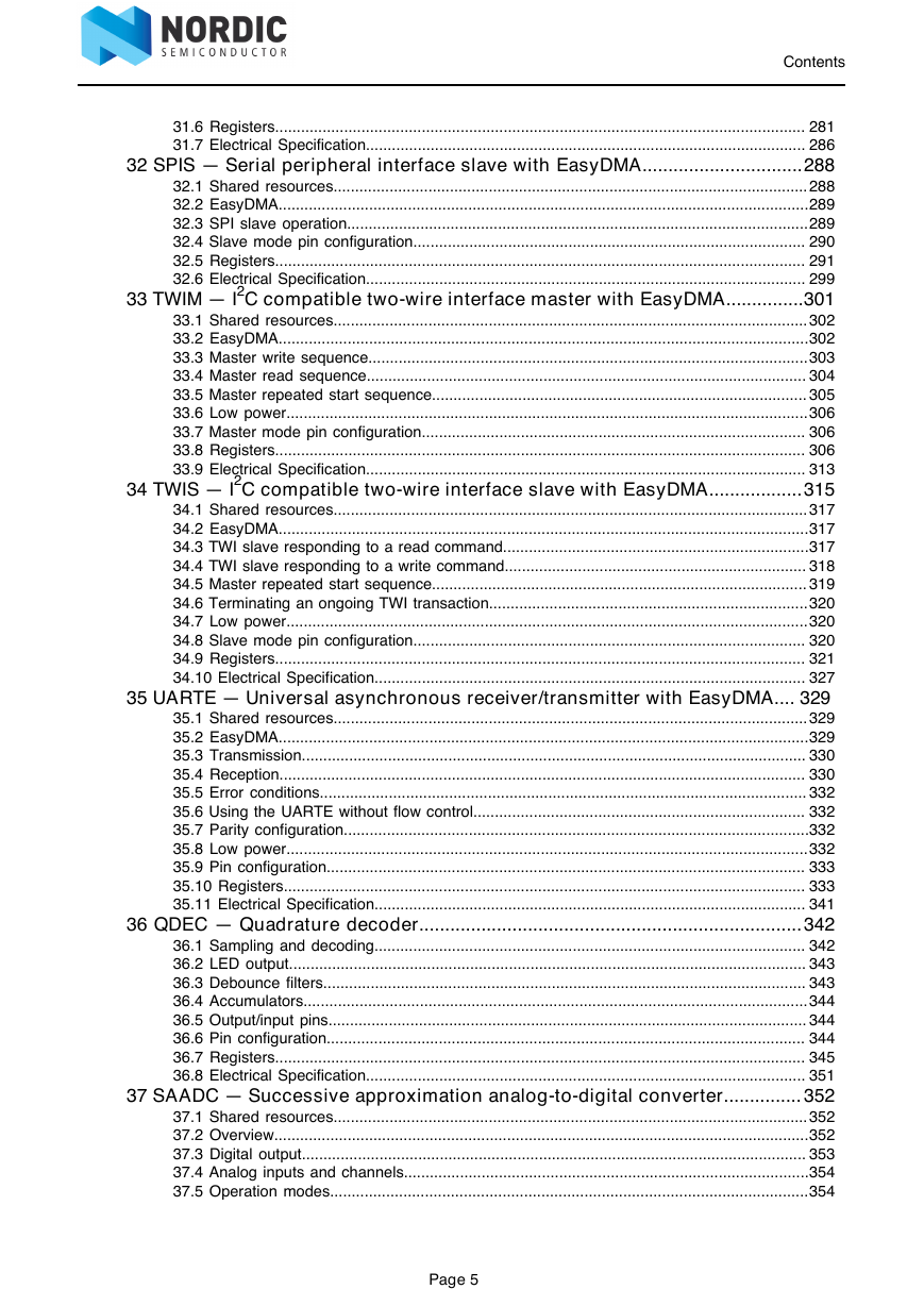
32 SPIS — Serial peripheral interface slave with EasyDMA
32.1 Shared resources
32.2 EasyDMA
32.3 SPI slave operation
32.4 Slave mode pin configuration
32.5 Registers
32.5.1 SHORTS
32.5.2 INTENSET
32.5.3 INTENCLR
32.5.4 SEMSTAT
32.5.5 STATUS
32.5.6 ENABLE
32.5.7 PSELSCK ( Deprecated )
32.5.8 PSELMISO ( Deprecated )
32.5.9 PSELMOSI ( Deprecated )
32.5.10 PSELCSN ( Deprecated )
32.5.11 PSEL.SCK
32.5.12 PSEL.MISO
32.5.13 PSEL.MOSI
32.5.14 PSEL.CSN
32.5.15 RXDPTR ( Deprecated )
32.5.16 MAXRX ( Deprecated )
32.5.17 AMOUNTRX ( Deprecated )
32.5.18 RXD.PTR
32.5.19 RXD.MAXCNT
32.5.20 RXD.AMOUNT
32.5.21 TXDPTR ( Deprecated )
32.5.22 MAXTX ( Deprecated )
32.5.23 AMOUNTTX ( Deprecated )
32.5.24 TXD.PTR
32.5.25 TXD.MAXCNT
32.5.26 TXD.AMOUNT
32.5.27 CONFIG
32.5.28 DEF
32.5.29 ORC
32.6 Electrical Specification
32.6.1 SPIS slave interface electrical specifications
32.6.2 Serial Peripheral Interface Slave (SPIS) timing specifications
33 TWIM — I2C compatible two-wire interface master with EasyDMA
33.1 Shared resources
33.2 EasyDMA
33.2.1 EasyDMA list
EasyDMA array list
33.3 Master write sequence
33.4 Master read sequence
33.5 Master repeated start sequence
33.6 Low power
33.7 Master mode pin configuration
33.8 Registers
33.8.1 SHORTS
33.8.2 INTEN
33.8.3 INTENSET
33.8.4 INTENCLR
33.8.5 ERRORSRC
33.8.6 ENABLE
33.8.7 PSEL.SCL
33.8.8 PSEL.SDA
33.8.9 FREQUENCY
33.8.10 RXD.PTR
33.8.11 RXD.MAXCNT
33.8.12 RXD.AMOUNT
33.8.13 RXD.LIST
33.8.14 TXD.PTR
33.8.15 TXD.MAXCNT
33.8.16 TXD.AMOUNT
33.8.17 TXD.LIST
33.8.18 ADDRESS
33.9 Electrical Specification
33.9.1 TWIM interface electrical specifications
33.9.2 Two Wire Interface Master (TWIM) timing specifications
34 TWIS — I2C compatible two-wire interface slave with EasyDMA
34.1 Shared resources
34.2 EasyDMA
34.3 TWI slave responding to a read command
34.4 TWI slave responding to a write command
34.5 Master repeated start sequence
34.6 Terminating an ongoing TWI transaction
34.7 Low power
34.8 Slave mode pin configuration
34.9 Registers
34.9.1 SHORTS
34.9.2 INTEN
34.9.3 INTENSET
34.9.4 INTENCLR
34.9.5 ERRORSRC
34.9.6 MATCH
34.9.7 ENABLE
34.9.8 PSEL.SCL
34.9.9 PSEL.SDA
34.9.10 RXD.PTR
34.9.11 RXD.MAXCNT
34.9.12 RXD.AMOUNT
34.9.13 TXD.PTR
34.9.14 TXD.MAXCNT
34.9.15 TXD.AMOUNT
34.9.16 ADDRESS[0]
34.9.17 ADDRESS[1]
34.9.18 CONFIG
34.9.19 ORC
34.10 Electrical Specification
34.10.1 TWIS slave interface electrical specifications
34.10.2 TWIS slave timing specifications
35 UARTE — Universal asynchronous receiver/transmitter with EasyDMA
35.1 Shared resources
35.2 EasyDMA
35.3 Transmission
35.4 Reception
35.5 Error conditions
35.6 Using the UARTE without flow control
35.7 Parity configuration
35.8 Low power
35.9 Pin configuration
35.10 Registers
35.10.1 SHORTS
35.10.2 INTEN
35.10.3 INTENSET
35.10.4 INTENCLR
35.10.5 ERRORSRC
35.10.6 ENABLE
35.10.7 PSEL.RTS
35.10.8 PSEL.TXD
35.10.9 PSEL.CTS
35.10.10 PSEL.RXD
35.10.11 BAUDRATE
35.10.12 RXD.PTR
35.10.13 RXD.MAXCNT
35.10.14 RXD.AMOUNT
35.10.15 TXD.PTR
35.10.16 TXD.MAXCNT
35.10.17 TXD.AMOUNT
35.10.18 CONFIG
35.11 Electrical Specification
35.11.1 UARTE electrical specification
36 QDEC — Quadrature decoder
36.1 Sampling and decoding
36.2 LED output
36.3 Debounce filters
36.4 Accumulators
36.5 Output/input pins
36.6 Pin configuration
36.7 Registers
36.7.1 SHORTS
36.7.2 INTENSET
36.7.3 INTENCLR
36.7.4 ENABLE
36.7.5 LEDPOL
36.7.6 SAMPLEPER
36.7.7 SAMPLE
36.7.8 REPORTPER
36.7.9 ACC
36.7.10 ACCREAD
36.7.11 PSEL.LED
36.7.12 PSEL.A
36.7.13 PSEL.B
36.7.14 DBFEN
36.7.15 LEDPRE
36.7.16 ACCDBL
36.7.17 ACCDBLREAD
36.8 Electrical Specification
36.8.1 QDEC Electrical Specification
37 SAADC — Successive approximation analog-to-digital converter
37.1 Shared resources
37.2 Overview
37.3 Digital output
37.4 Analog inputs and channels
37.5 Operation modes
37.5.1 One-shot mode
37.5.2 Continuous mode
37.5.3 Oversampling
37.5.4 Scan mode
37.6 EasyDMA
37.7 Resistor ladder
37.8 Reference
37.9 Acquisition time
37.10 Limits event monitoring
37.11 Registers
37.11.1 INTEN
37.11.2 INTENSET
37.11.3 INTENCLR
37.11.4 STATUS
37.11.5 ENABLE
37.11.6 CH[0].PSELP
37.11.7 CH[0].PSELN
37.11.8 CH[0].CONFIG
37.11.9 CH[0].LIMIT
37.11.10 CH[1].PSELP
37.11.11 CH[1].PSELN
37.11.12 CH[1].CONFIG
37.11.13 CH[1].LIMIT
37.11.14 CH[2].PSELP
37.11.15 CH[2].PSELN
37.11.16 CH[2].CONFIG
37.11.17 CH[2].LIMIT
37.11.18 CH[3].PSELP
37.11.19 CH[3].PSELN
37.11.20 CH[3].CONFIG
37.11.21 CH[3].LIMIT
37.11.22 CH[4].PSELP
37.11.23 CH[4].PSELN
37.11.24 CH[4].CONFIG
37.11.25 CH[4].LIMIT
37.11.26 CH[5].PSELP
37.11.27 CH[5].PSELN
37.11.28 CH[5].CONFIG
37.11.29 CH[5].LIMIT
37.11.30 CH[6].PSELP
37.11.31 CH[6].PSELN
37.11.32 CH[6].CONFIG
37.11.33 CH[6].LIMIT
37.11.34 CH[7].PSELP
37.11.35 CH[7].PSELN
37.11.36 CH[7].CONFIG
37.11.37 CH[7].LIMIT
37.11.38 RESOLUTION
37.11.39 OVERSAMPLE
37.11.40 SAMPLERATE
37.11.41 RESULT.PTR
37.11.42 RESULT.MAXCNT
37.11.43 RESULT.AMOUNT
37.12 Electrical Specification
37.12.1 SAADC Electrical Specification
37.13 Performance factors
38 COMP — Comparator
38.1 Shared resources
38.2 Differential mode
38.3 Single-ended mode
38.4 Pin configuration
38.5 Registers
38.5.1 SHORTS
38.5.2 INTEN
38.5.3 INTENSET
38.5.4 INTENCLR
38.5.5 RESULT
38.5.6 ENABLE
38.5.7 PSEL
38.5.8 REFSEL
38.5.9 EXTREFSEL
38.5.10 TH
38.5.11 MODE
38.5.12 HYST
38.5.13 ISOURCE
38.6 Electrical Specification
38.6.1 COMP Electrical Specification
39 LPCOMP — Low power comparator
39.1 Shared resources
39.2 Pin configuration
39.3 Registers
39.3.1 SHORTS
39.3.2 INTENSET
39.3.3 INTENCLR
39.3.4 RESULT
39.3.5 ENABLE
39.3.6 PSEL
39.3.7 REFSEL
39.3.8 EXTREFSEL
39.3.9 ANADETECT
39.3.10 HYST
39.4 Electrical Specification
39.4.1 LPCOMP Electrical Specification
40 WDT — Watchdog timer
40.1 Reload criteria
40.2 Temporarily pausing the watchdog
40.3 Watchdog reset
40.4 Registers
40.4.1 INTENSET
40.4.2 INTENCLR
40.4.3 RUNSTATUS
40.4.4 REQSTATUS
40.4.5 CRV
40.4.6 RREN
40.4.7 CONFIG
40.4.8 RR[0]
40.4.9 RR[1]
40.4.10 RR[2]
40.4.11 RR[3]
40.4.12 RR[4]
40.4.13 RR[5]
40.4.14 RR[6]
40.4.15 RR[7]
40.5 Electrical Specification
40.5.1 Watchdog Timer Electrical Specification
41 SWI — Software interrupts
41.1 Registers
42 NFCT — Near field communication tag
42.1 Overview
42.2 Pin configuration
42.3 EasyDMA
42.4 Collision resolution
42.5 Frame timing controller
42.6 Frame assembler
42.7 Frame disassembler
42.8 Antenna interface
42.9 NFCT antenna recommendations
42.10 Battery protection
42.11 References
42.12 Registers
42.12.1 SHORTS
42.12.2 INTEN
42.12.3 INTENSET
42.12.4 INTENCLR
42.12.5 ERRORSTATUS
42.12.6 FRAMESTATUS.RX
42.12.7 CURRENTLOADCTRL
42.12.8 FIELDPRESENT
42.12.9 FRAMEDELAYMIN
42.12.10 FRAMEDELAYMAX
42.12.11 FRAMEDELAYMODE
42.12.12 PACKETPTR
42.12.13 MAXLEN
42.12.14 TXD.FRAMECONFIG
42.12.15 TXD.AMOUNT
42.12.16 RXD.FRAMECONFIG
42.12.17 RXD.AMOUNT
42.12.18 NFCID1_LAST
42.12.19 NFCID1_2ND_LAST
42.12.20 NFCID1_3RD_LAST
42.12.21 SENSRES
42.12.22 SELRES
42.13 Electrical Specification
42.13.1 NFCT Electrical Specification
42.13.2 NFCT Timing Parameters
43 PDM — Pulse density modulation interface
43.1 Master clock generator
43.2 Module operation
43.3 Decimation filter
43.4 EasyDMA
43.5 Hardware example
43.6 Pin configuration
43.7 Registers
43.7.1 INTEN
43.7.2 INTENSET
43.7.3 INTENCLR
43.7.4 ENABLE
43.7.5 PDMCLKCTRL
43.7.6 MODE
43.7.7 GAINL
43.7.8 GAINR
43.7.9 PSEL.CLK
43.7.10 PSEL.DIN
43.7.11 SAMPLE.PTR
43.7.12 SAMPLE.MAXCNT
43.8 Electrical Specification
43.8.1 PDM Electrical Specification
44 I2S — Inter-IC sound interface
44.1 Mode
44.2 Transmitting and receiving
44.3 Left right clock (LRCK)
44.4 Serial clock (SCK)
44.5 Master clock (MCK)
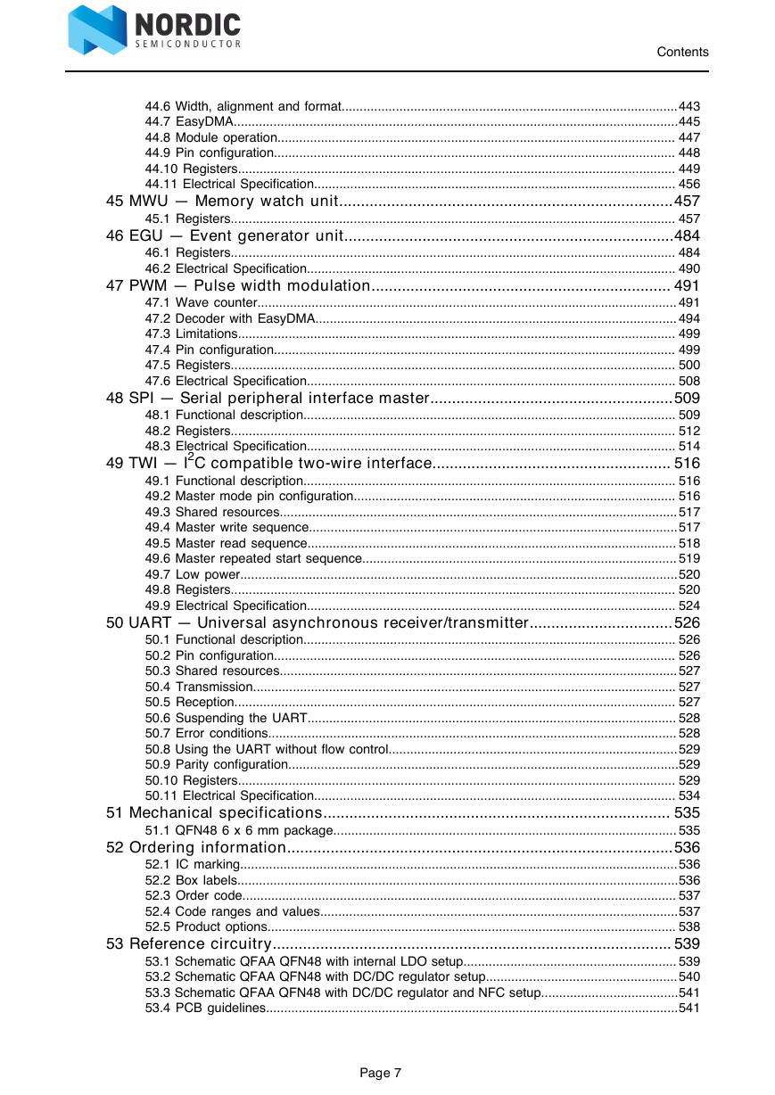
44.6 Width, alignment and format
44.7 EasyDMA
44.8 Module operation
44.9 Pin configuration
44.10 Registers
44.10.1 INTEN
44.10.2 INTENSET
44.10.3 INTENCLR
44.10.4 ENABLE
44.10.5 CONFIG.MODE
44.10.6 CONFIG.RXEN
44.10.7 CONFIG.TXEN
44.10.8 CONFIG.MCKEN
44.10.9 CONFIG.MCKFREQ
44.10.10 CONFIG.RATIO
44.10.11 CONFIG.SWIDTH
44.10.12 CONFIG.ALIGN
44.10.13 CONFIG.FORMAT
44.10.14 CONFIG.CHANNELS
44.10.15 RXD.PTR
44.10.16 TXD.PTR
44.10.17 RXTXD.MAXCNT
44.10.18 PSEL.MCK
44.10.19 PSEL.SCK
44.10.20 PSEL.LRCK
44.10.21 PSEL.SDIN
44.10.22 PSEL.SDOUT
44.11 Electrical Specification
44.11.1 I2S timing specification
45 MWU — Memory watch unit
45.1 Registers
45.1.1 INTEN
45.1.2 INTENSET
45.1.3 INTENCLR
45.1.4 NMIEN
45.1.5 NMIENSET
45.1.6 NMIENCLR
45.1.7 PERREGION[0].SUBSTATWA
45.1.8 PERREGION[0].SUBSTATRA
45.1.9 PERREGION[1].SUBSTATWA
45.1.10 PERREGION[1].SUBSTATRA
45.1.11 REGIONEN
45.1.12 REGIONENSET
45.1.13 REGIONENCLR
45.1.14 REGION[0].START
45.1.15 REGION[0].END
45.1.16 REGION[1].START
45.1.17 REGION[1].END
45.1.18 REGION[2].START
45.1.19 REGION[2].END
45.1.20 REGION[3].START
45.1.21 REGION[3].END
45.1.22 PREGION[0].START
45.1.23 PREGION[0].END
45.1.24 PREGION[0].SUBS
45.1.25 PREGION[1].START
45.1.26 PREGION[1].END
45.1.27 PREGION[1].SUBS
46 EGU — Event generator unit
46.1 Registers
46.1.1 INTEN
46.1.2 INTENSET
46.1.3 INTENCLR
46.2 Electrical Specification
46.2.1 EGU Electrical Specification
47 PWM — Pulse width modulation
47.1 Wave counter
47.2 Decoder with EasyDMA
47.3 Limitations
47.4 Pin configuration
47.5 Registers
47.5.1 SHORTS
47.5.2 INTEN
47.5.3 INTENSET
47.5.4 INTENCLR
47.5.5 ENABLE
47.5.6 MODE
47.5.7 COUNTERTOP
47.5.8 PRESCALER
47.5.9 DECODER
47.5.10 LOOP
47.5.11 SEQ[0].PTR
47.5.12 SEQ[0].CNT
47.5.13 SEQ[0].REFRESH
47.5.14 SEQ[0].ENDDELAY
47.5.15 SEQ[1].PTR
47.5.16 SEQ[1].CNT
47.5.17 SEQ[1].REFRESH
47.5.18 SEQ[1].ENDDELAY
47.5.19 PSEL.OUT[0]
47.5.20 PSEL.OUT[1]
47.5.21 PSEL.OUT[2]
47.5.22 PSEL.OUT[3]
47.6 Electrical Specification
47.6.1 PWM Electrical Specification
48 SPI — Serial peripheral interface master
48.1 Functional description
48.1.1 SPI master mode pin configuration
48.1.2 Shared resources
48.1.3 SPI master transaction sequence
48.2 Registers
48.2.1 INTENSET
48.2.2 INTENCLR
48.2.3 ENABLE
48.2.4 PSEL.SCK
48.2.5 PSEL.MOSI
48.2.6 PSEL.MISO
48.2.7 RXD
48.2.8 TXD
48.2.9 FREQUENCY
48.2.10 CONFIG
48.3 Electrical Specification
48.3.1 SPI master interface
48.3.2 Serial Peripheral Interface (SPI) Master timing specifications
49 TWI — I2C compatible two-wire interface
49.1 Functional description
49.2 Master mode pin configuration
49.3 Shared resources
49.4 Master write sequence
49.5 Master read sequence
49.6 Master repeated start sequence
49.7 Low power
49.8 Registers
49.8.1 SHORTS
49.8.2 INTENSET
49.8.3 INTENCLR
49.8.4 ERRORSRC
49.8.5 ENABLE
49.8.6 PSELSCL
49.8.7 PSELSDA
49.8.8 RXD
49.8.9 TXD
49.8.10 FREQUENCY
49.8.11 ADDRESS
49.9 Electrical Specification
49.9.1 TWI interface electrical specifications
49.9.2 Two Wire Interface (TWI) timing specifications
50 UART — Universal asynchronous receiver/transmitter
50.1 Functional description
50.2 Pin configuration
50.3 Shared resources
50.4 Transmission
50.5 Reception
50.6 Suspending the UART
50.7 Error conditions
50.8 Using the UART without flow control
50.9 Parity configuration
50.10 Registers
50.10.1 SHORTS
50.10.2 INTENSET
50.10.3 INTENCLR
50.10.4 ERRORSRC
50.10.5 ENABLE
50.10.6 PSELRTS
50.10.7 PSELTXD
50.10.8 PSELCTS
50.10.9 PSELRXD
50.10.10 RXD
50.10.11 TXD
50.10.12 BAUDRATE
50.10.13 CONFIG
50.11 Electrical Specification
50.11.1 UART electrical specification
51 Mechanical specifications
51.1 QFN48 6 x 6 mm package
52 Ordering information
52.1 IC marking
52.2 Box labels
52.3 Order code
52.4 Code ranges and values
52.5 Product options
53 Reference circuitry
53.1 Schematic QFAA QFN48 with internal LDO setup
53.2 Schematic QFAA QFN48 with DC/DC regulator setup
53.3 Schematic QFAA QFN48 with DC/DC regulator and NFC setup
53.4 PCB guidelines
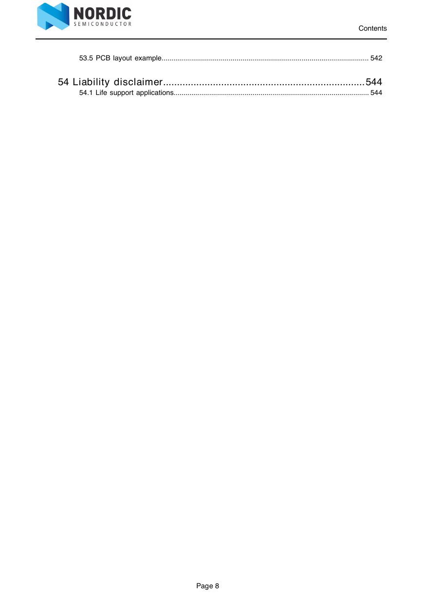
53.5 PCB layout example
54 Liability disclaimer
54.1 Life support applications
54.1.1 RoHS and REACH statement



 2023年江西萍乡中考道德与法治真题及答案.doc
 2012年重庆南川中考生物真题及答案.doc
 2013年江西师范大学地理学综合及文艺理论基础考研真题.doc
 2020年四川甘孜小升初语文真题及答案I卷.doc
 2020年注册岩土工程师专业基础考试真题及答案.doc
 2023-2024学年福建省厦门市九年级上学期数学月考试题及答案.doc
 2021-2022学年辽宁省沈阳市大东区九年级上学期语文期末试题及答案.doc
 2022-2023学年北京东城区初三第一学期物理期末试卷及答案.doc
 2018上半年江西教师资格初中地理学科知识与教学能力真题及答案.doc
 2012年河北国家公务员申论考试真题及答案-省级.doc
 2020-2021学年江苏省扬州市江都区邵樊片九年级上学期数学第一次质量检测试题及答案.doc
 2022下半年黑龙江教师资格证中学综合素质真题及答案.doc