logo资料库

Cortex-A53_MSM8216、MSM8616、MSM8916数据手册_(高通).pdf

第1页 / 共117页
第2页 / 共117页
第3页 / 共117页
第4页 / 共117页
第5页 / 共117页
第6页 / 共117页
第7页 / 共117页
第8页 / 共117页
资料共117页,剩余部分请下载后查看
MSM8216/MSM8616/MSM8916 Device Specification
Revision history
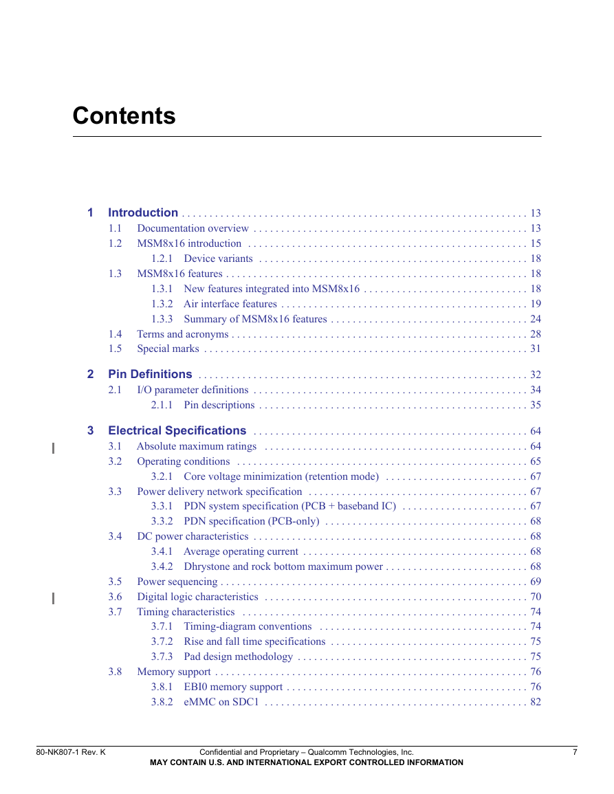
Contents
1 Introduction
1.1 Documentation overview
1.2 MSM8x16 introduction
1.2.1 Device variants
1.3 MSM8x16 features
1.3.1 New features integrated into MSM8x16
1.3.2 Air interface features
1.3.3 Summary of MSM8x16 features
1.4 Terms and acronyms
1.5 Special marks
2 Pin Definitions
2.1 I/O parameter definitions
2.1.1 Pin descriptions
3 Electrical Specifications
3.1 Absolute maximum ratings
3.2 Operating conditions
3.2.1 Core voltage minimization (retention mode)
3.3 Power delivery network specification
3.3.1 PDN system specification (PCB + baseband IC)
3.3.2 PDN specification (PCB-only)
3.4 DC power characteristics
3.4.1 Average operating current
3.4.2 Dhrystone and rock bottom maximum power
3.5 Power sequencing
3.6 Digital logic characteristics
3.7 Timing characteristics
3.7.1 Timing-diagram conventions
3.7.2 Rise and fall time specifications
3.7.3 Pad design methodology
3.8 Memory support
3.8.1 EBI0 memory support
3.8.2 eMMC on SDC1
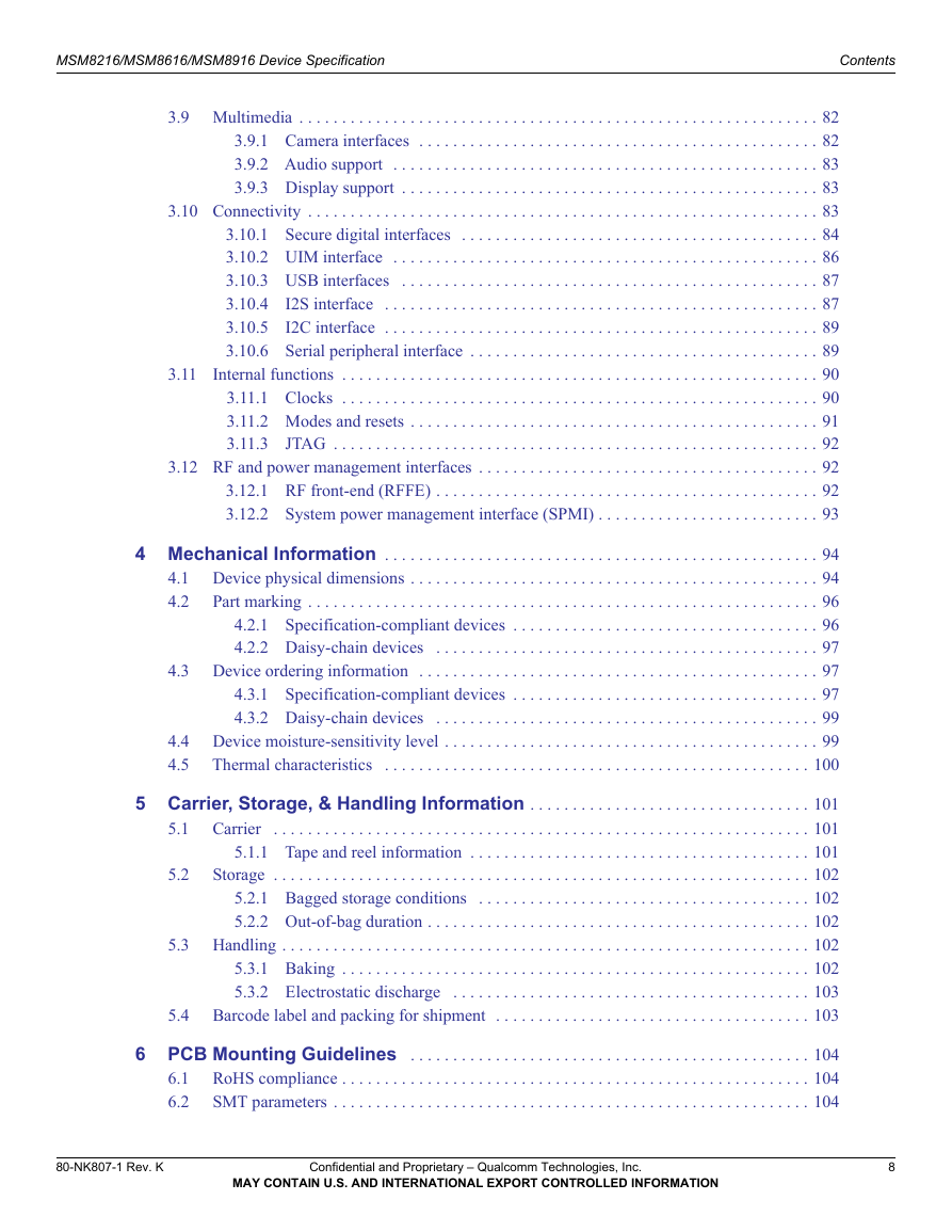
3.9 Multimedia
3.9.1 Camera interfaces
3.9.2 Audio support
3.9.3 Display support
3.10 Connectivity
3.10.1 Secure digital interfaces
3.10.2 UIM interface
3.10.3 USB interfaces
3.10.4 I2S interface
3.10.5 I2C interface
3.10.6 Serial peripheral interface
3.11 Internal functions
3.11.1 Clocks
3.11.2 Modes and resets
3.11.3 JTAG
3.12 RF and power management interfaces
3.12.1 RF front-end (RFFE)
3.12.2 System power management interface (SPMI)
4 Mechanical Information
4.1 Device physical dimensions
4.2 Part marking
4.2.1 Specification-compliant devices
4.2.2 Daisy-chain devices
4.3 Device ordering information
4.3.1 Specification-compliant devices
4.3.2 Daisy-chain devices
4.4 Device moisture-sensitivity level
4.5 Thermal characteristics
5 Carrier, Storage, & Handling Information
5.1 Carrier
5.1.1 Tape and reel information
5.2 Storage
5.2.1 Bagged storage conditions
5.2.2 Out-of-bag duration
5.3 Handling
5.3.1 Baking
5.3.2 Electrostatic discharge
5.4 Barcode label and packing for shipment
6 PCB Mounting Guidelines
6.1 RoHS compliance
6.2 SMT parameters
6.2.1 Land pad and stencil design
6.2.2 Reflow profile
6.2.3 SMT peak package-body temperature
6.2.4 SMT process verification
6.3 Daisy-chain components
6.4 Board-level reliability
6.5 High-temperature warpage
7 Part Reliability
7.1 Reliability evaluation summary
7.1.1 MSM8x16 reliability evaluation report for device from GF-F8
7.1.2 MSM8x16 reliability evaluation report for device from TSMC-F15
7.1.3 MSM8916 reliability evaluation report for device from Samsung
7.2 Qualification sample description
Qualcomm Technologies, Inc. MSM8216/MSM8616/MSM8916 Device Specification 80-NK807-1 Rev. K July 23, 2015 Confidential and Proprietary – Qualcomm Technologies, Inc. © 2013, 2014, 2015 Qualcomm Technologies, Inc. All rights reserved. NO PUBLIC DISCLOSURE PERMITTED: Please report postings of this document on public servers or websites to: DocCtrlAgent@qualcomm.com. Not to be used, copied, reproduced, or modified in whole or in part, nor its contents revealed in any manner to others without the express written permission of Qualcomm Technologies, Inc. MSM is a product of Qualcomm Technologies, Inc.
Questions or comments: https://createpoint.qti.qualcomm.com/ Restricted Distribution: Not to be distributed to anyone who is not an employee of either Qualcomm Technologies, Inc. or its affiliated companies without the express approval of Qualcomm Configuration Management. Qualcomm is a trademark of Qualcomm Incorporated, registered in the United States and other countries. MSM is a trademark of Qualcomm Incorporated, registered in the United States and other countries. All Qualcomm Incorporated trademarks are used with permission. Other product and brand names may be trademarks or registered trademarks of their respective owners. This technical data may be subject to U.S. and international export, re-export, or transfer (“export”) laws. Diversion contrary to U.S. and international law is strictly prohibited. Qualcomm Technologies, Inc. 5775 Morehouse Drive San Diego, CA 92121 U.S.A.
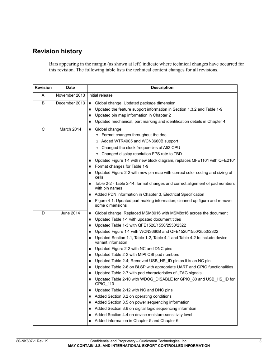
Revision history Bars appearing in the margin (as shown at left) indicate where technical changes have occurred for this revision. The following table lists the technical content changes for all revisions. Revision Date Description A B C November 2013 Initial release December 2013  Global change: Updated package dimension  Updated the feature support information in Section  Updated pin map information in Chapter 2  Updated mechanical, part marking and identification details in Chapter 4  Global change: 1.3.2 and Table 1-9 March 2014  Format changes throughout the doc  Added WTR4905 and WCN3660B support  Changed the clock frequencies of A53 CPU  Changed display resolution FPS rate to TBD 1-1 with new block diagram, replaces QFE1101 with QFE2101  Updated Figure  Format changes for Table  Updated Figure 1-9 cells  Table with pin names 2-2 with new pin map with correct color coding and sizing of 2-2 - Table 2-14: format changes and correct alignment of pad numbers D June 2014  Added PDN information in Chapter 3, Electrical Specification  Figure 4-1: Updated part making information; cleaned up figure and remove some dimensions  Global change: Replaced MSM8916 with MSM8x16 across the document  Updated Table  Updated Table  Updated Figure  Updated Section variant infomation 1-1 with updated document titles 1-3 with QFE1520/1550/2550/2322 1-1 with WCN3660B and QFE1520/1550/2550/2322 1.1, Table 4-2 to include device 4-1 and Table 1-2, Table  Updated Figure  Updated Table  Updated Table  Updated Table  Updated Table  Updated Table 2-2 with NC and DNC pins 2-3 with MIPI CSI pad numbers 2-4; Removed USB_HS_ID pin as it is an NC pin 2-6 on BLSP with appropriate UART and GPIO functionalities 2-7 with pad characteristics of JTAG signals 2-10 with WDOG_DISABLE for GPIO_80 and USB_HS_ID for GPIO_110  Updated Table  Added Section  Added Section  Added Section  Added Section  Added information in Chapter 5 and Chapter 6 2-12 with NC and DNC pins 3.2 on operating conditions 3.5 on power sequencing information 3.6 on digital logic sequencing informtion 4.4 on device moisture-sensitivity level 80-NK807-1 Rev. K Confidential and Proprietary – Qualcomm Technologies, Inc. MAY CONTAIN U.S. AND INTERNATIONAL EXPORT CONTROLLED INFORMATION 3
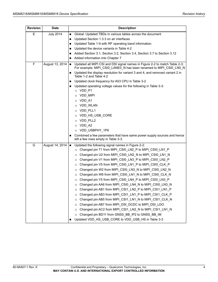
MSM8216/MSM8616/MSM8916 Device Specification Revision history Revision Date Description E F July 2014 1.3.3 on air interfaces  Global: Updated TBDs in various tables across the document  Updated Section  Updated Table  Updated the device variants in Table  Added Section  Added information into Chapter 7 1-9 with RF operating band information 4-2 3.2, Section 3.1, Section 3.4, Section 3.7 to Section 3.12 August 13, 2014  Updated all MIPI CSI and DSI signal names in Figure 2-2 to match Table 2-3; For example: MIPI_CSI0_LANE0_N has been renamed to MIPI_CSI0_LN0_N  Updated the display resolution for variant 3 and 4; and removed variant 2 in Table 1-2 and Table 4-2  Updated clock frequency for A53 CPU in Table 3-2  Updated operating voltage values for the following in Table 3-3:  VDD_P1  VDD_MIPI  VDD_A1  VDD_WLAN  VDD_PLL1  VDD_HS_USB_CORE  VDD_PLL2  VDD_A2  VDD_USBPHY_1P8  Combined a few parameters that have same power supply sources and hence left a few rows empty in Table 3-3. G August 14, 2014  Updated the following signal names in Figure 2-2:  Changed pin T1 from MIPI_CSI0_LN2_P to MIPI_CSI0_LN1_P  Changed pin U2 from MIPI_CSI0_LN2_N to MIPI_CSI0_LN1_N  Changed pin V1 from MIPI_CSI0_LN3_P to MIPI_CSI0_LN2_P  Changed pin V5 from MIPI_CSI0_LN1_P to MIPI_CSI0_CLK_P  Changed pin W2 from MIPI_CSI0_LN3_N to MIPI_CSI0_LN2_N  Changed pin W6 from MIPI_CSI0_LN1_N to MIPI_CSI0_CLK_N  Changed pin Y5 from MIPI_CSI0_LN4_P to MIPI_CSI0_LN3_P  Changed pin AA6 from MIPI_CSI0_LN4_N to MIPI_CSI0_LN3_N  Changed pin AB1 from MIPI_CSI1_LN2_P to MIPI_CSI1_LN1_P  Changed pin AB3 from MIPI_CSI1_LN1_P to MIPI_CSI1_CLK_P  Changed pin AB5 from MIPI_CSI1_LN1_N to MIPI_CSI1_CLK_N  Changed pin AB7 from MIPI_DSI_DCDC to MIPI_DSI_LDO  Changed pin AC2 from MIPI_CSI1_LN2_N to MIPI_CSI1_LN1_N  Changed pin BD11 from GNSS_BB_IP2 to GNSS_BB_IM  Updated VDD_HS_USB_CORE to VDD_USB_HS in Table 3-3 80-NK807-1 Rev. K Confidential and Proprietary – Qualcomm Technologies, Inc. MAY CONTAIN U.S. AND INTERNATIONAL EXPORT CONTROLLED INFORMATION 4
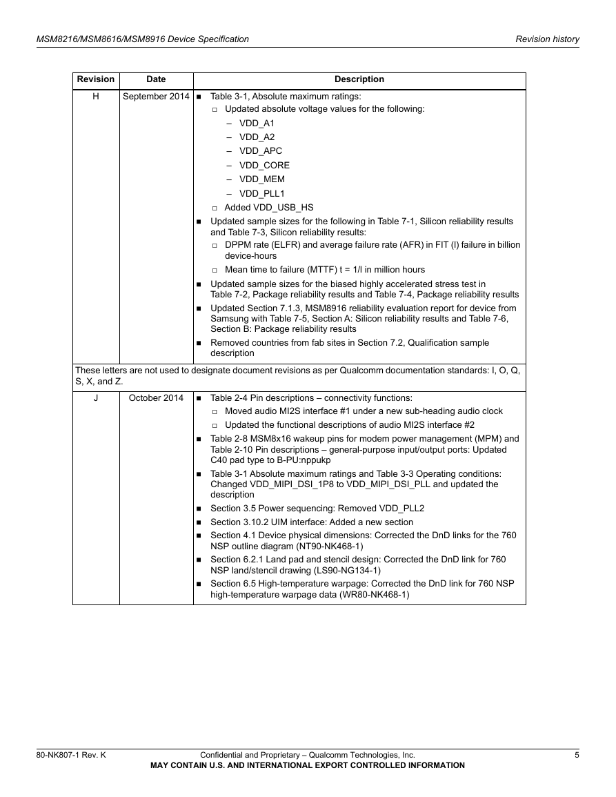
MSM8216/MSM8616/MSM8916 Device Specification Revision history Revision Date Description H September 2014  Table 3-1, Absolute maximum ratings:  Updated absolute voltage values for the following: – VDD_A1 – VDD_A2 – VDD_APC – VDD_CORE – VDD_MEM – VDD_PLL1  Added VDD_USB_HS  Updated sample sizes for the following in Table 7-1, Silicon reliability results and Table  DPPM rate (ELFR) and average failure rate (AFR) in FIT (l) failure in billion 7-3, Silicon reliability results: device-hours  Mean time to failure (MTTF) t = 1/l in million hours  Updated sample sizes for the biased highly accelerated stress test in 7-2, Package reliability results and Table 7-4, Package reliability results 7.1.3, MSM8916 reliability evaluation report for device from  Updated Section 7-5, Section A: Silicon reliability results and Table 7-6, Table Samsung with Table Section B: Package reliability results description  Removed countries from fab sites in Section 7.2, Qualification sample These letters are not used to designate document revisions as per Qualcomm documentation standards: I, O, Q, S, X, and Z. J October 2014  Table 2-4 Pin descriptions – connectivity functions:  Moved audio MI2S interface #1 under a new sub-heading audio clock  Updated the functional descriptions of audio MI2S interface #2  Table Table C40 pad type to B-PU:nppukp 2-8 MSM8x16 wakeup pins for modem power management (MPM) and 2-10 Pin descriptions – general-purpose input/output ports: Updated  Table  Section  Section  Section 3-1 Absolute maximum ratings and Table 3.5 Power sequencing: Removed VDD_PLL2 3.10.2 UIM interface: Added a new section 4.1 Device physical dimensions: Corrected the DnD links for the 760 3-3 Operating conditions: Changed VDD_MIPI_DSI_1P8 to VDD_MIPI_DSI_PLL and updated the description NSP outline diagram (NT90-NK468-1) NSP land/stencil drawing (LS90-NG134-1) high-temperature warpage data (WR80-NK468-1) 6.5 High-temperature warpage: Corrected the DnD link for 760 NSP 6.2.1 Land pad and stencil design: Corrected the DnD link for 760  Section  Section 80-NK807-1 Rev. K Confidential and Proprietary – Qualcomm Technologies, Inc. MAY CONTAIN U.S. AND INTERNATIONAL EXPORT CONTROLLED INFORMATION 5
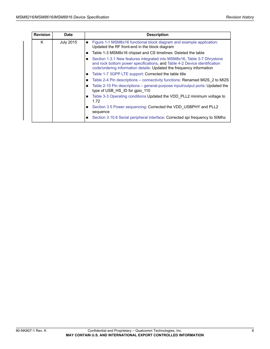
MSM8216/MSM8616/MSM8916 Device Specification Revision history Revision Date K July 2015  Figure 1-1 MSM8x16 functional block diagram and example application: Updated the RF front-end in the block diagram Description  Table 1-3 MSM8x16 chipset and CS timelines: Deleted the table  Section and rock bottom power specifications, and Table code/ordering information details: Updated the frequency information 1.3.1 New features integrated into MSM8x16, Table 4-2 Device identification 3-7 Dhrystone  Table  Table  Table 1-7 3GPP LTE support: Corrected the table title 2-4 Pin descriptions – connectivity functions: Renamed MI2S_2 to MI2S 2-10 Pin descriptions – general-purpose input/output ports: Updated the type of USB_HS_ID for gpio_110 3-3 Operating conditions Updated the VDD_PLL2 minimum voltage to  Table 1.72 sequence  Section  Section 3.5 Power sequencing: Corrected the VDD_USBPHY and PLL2 3.10.6 Serial peripheral interface: Corrected spi frequency to 50Mhz 80-NK807-1 Rev. K Confidential and Proprietary – Qualcomm Technologies, Inc. MAY CONTAIN U.S. AND INTERNATIONAL EXPORT CONTROLLED INFORMATION 6
Contents 1 Introduction . . . . . . . . . . . . . . . . . . . . . . . . . . . . . . . . . . . . . . . . . . . . . . . . . . . . . . . . . . . . . . . 13 1.1 Documentation overview . . . . . . . . . . . . . . . . . . . . . . . . . . . . . . . . . . . . . . . . . . . . . . . . . . 13 1.2 MSM8x16 introduction . . . . . . . . . . . . . . . . . . . . . . . . . . . . . . . . . . . . . . . . . . . . . . . . . . . 15 1.2.1 Device variants . . . . . . . . . . . . . . . . . . . . . . . . . . . . . . . . . . . . . . . . . . . . . . . . . 18 1.3 MSM8x16 features . . . . . . . . . . . . . . . . . . . . . . . . . . . . . . . . . . . . . . . . . . . . . . . . . . . . . . . 18 1.3.1 New features integrated into MSM8x16 . . . . . . . . . . . . . . . . . . . . . . . . . . . . . . 18 1.3.2 Air interface features . . . . . . . . . . . . . . . . . . . . . . . . . . . . . . . . . . . . . . . . . . . . . 19 1.3.3 Summary of MSM8x16 features . . . . . . . . . . . . . . . . . . . . . . . . . . . . . . . . . . . . 24 Terms and acronyms . . . . . . . . . . . . . . . . . . . . . . . . . . . . . . . . . . . . . . . . . . . . . . . . . . . . . . 28 Special marks . . . . . . . . . . . . . . . . . . . . . . . . . . . . . . . . . . . . . . . . . . . . . . . . . . . . . . . . . . . 31 1.4 1.5 2 Pin Definitions . . . . . . . . . . . . . . . . . . . . . . . . . . . . . . . . . . . . . . . . . . . . . . . . . . . . . . . . . . . . 32 I/O parameter definitions . . . . . . . . . . . . . . . . . . . . . . . . . . . . . . . . . . . . . . . . . . . . . . . . . . 34 2.1.1 Pin descriptions . . . . . . . . . . . . . . . . . . . . . . . . . . . . . . . . . . . . . . . . . . . . . . . . . 35 2.1 3.3 3 Electrical Specifications . . . . . . . . . . . . . . . . . . . . . . . . . . . . . . . . . . . . . . . . . . . . . . . . . . 64 3.1 Absolute maximum ratings . . . . . . . . . . . . . . . . . . . . . . . . . . . . . . . . . . . . . . . . . . . . . . . . 64 3.2 Operating conditions . . . . . . . . . . . . . . . . . . . . . . . . . . . . . . . . . . . . . . . . . . . . . . . . . . . . . 65 3.2.1 Core voltage minimization (retention mode) . . . . . . . . . . . . . . . . . . . . . . . . . . 67 Power delivery network specification . . . . . . . . . . . . . . . . . . . . . . . . . . . . . . . . . . . . . . . . 67 3.3.1 PDN system specification (PCB + baseband IC) . . . . . . . . . . . . . . . . . . . . . . . 67 3.3.2 PDN specification (PCB-only) . . . . . . . . . . . . . . . . . . . . . . . . . . . . . . . . . . . . . 68 3.4 DC power characteristics . . . . . . . . . . . . . . . . . . . . . . . . . . . . . . . . . . . . . . . . . . . . . . . . . . 68 3.4.1 Average operating current . . . . . . . . . . . . . . . . . . . . . . . . . . . . . . . . . . . . . . . . . 68 3.4.2 Dhrystone and rock bottom maximum power . . . . . . . . . . . . . . . . . . . . . . . . . . 68 3.5 Power sequencing . . . . . . . . . . . . . . . . . . . . . . . . . . . . . . . . . . . . . . . . . . . . . . . . . . . . . . . . 69 3.6 Digital logic characteristics . . . . . . . . . . . . . . . . . . . . . . . . . . . . . . . . . . . . . . . . . . . . . . . . 70 Timing characteristics . . . . . . . . . . . . . . . . . . . . . . . . . . . . . . . . . . . . . . . . . . . . . . . . . . . . 74 3.7 3.7.1 Timing-diagram conventions . . . . . . . . . . . . . . . . . . . . . . . . . . . . . . . . . . . . . . 74 3.7.2 Rise and fall time specifications . . . . . . . . . . . . . . . . . . . . . . . . . . . . . . . . . . . . 75 3.7.3 Pad design methodology . . . . . . . . . . . . . . . . . . . . . . . . . . . . . . . . . . . . . . . . . . 75 3.8 Memory support . . . . . . . . . . . . . . . . . . . . . . . . . . . . . . . . . . . . . . . . . . . . . . . . . . . . . . . . . 76 3.8.1 EBI0 memory support . . . . . . . . . . . . . . . . . . . . . . . . . . . . . . . . . . . . . . . . . . . . 76 3.8.2 eMMC on SDC1 . . . . . . . . . . . . . . . . . . . . . . . . . . . . . . . . . . . . . . . . . . . . . . . . 82 80-NK807-1 Rev. K Confidential and Proprietary – Qualcomm Technologies, Inc. MAY CONTAIN U.S. AND INTERNATIONAL EXPORT CONTROLLED INFORMATION 7
MSM8216/MSM8616/MSM8916 Device Specification Contents 3.9 Multimedia . . . . . . . . . . . . . . . . . . . . . . . . . . . . . . . . . . . . . . . . . . . . . . . . . . . . . . . . . . . . . 82 3.9.1 Camera interfaces . . . . . . . . . . . . . . . . . . . . . . . . . . . . . . . . . . . . . . . . . . . . . . . 82 3.9.2 Audio support . . . . . . . . . . . . . . . . . . . . . . . . . . . . . . . . . . . . . . . . . . . . . . . . . . 83 3.9.3 Display support . . . . . . . . . . . . . . . . . . . . . . . . . . . . . . . . . . . . . . . . . . . . . . . . . 83 3.10 Connectivity . . . . . . . . . . . . . . . . . . . . . . . . . . . . . . . . . . . . . . . . . . . . . . . . . . . . . . . . . . . . 83 3.10.1 Secure digital interfaces . . . . . . . . . . . . . . . . . . . . . . . . . . . . . . . . . . . . . . . . . . 84 3.10.2 UIM interface . . . . . . . . . . . . . . . . . . . . . . . . . . . . . . . . . . . . . . . . . . . . . . . . . . 86 3.10.3 USB interfaces . . . . . . . . . . . . . . . . . . . . . . . . . . . . . . . . . . . . . . . . . . . . . . . . . 87 3.10.4 I2S interface . . . . . . . . . . . . . . . . . . . . . . . . . . . . . . . . . . . . . . . . . . . . . . . . . . . 87 3.10.5 I2C interface . . . . . . . . . . . . . . . . . . . . . . . . . . . . . . . . . . . . . . . . . . . . . . . . . . . 89 3.10.6 Serial peripheral interface . . . . . . . . . . . . . . . . . . . . . . . . . . . . . . . . . . . . . . . . . 89 3.11 Internal functions . . . . . . . . . . . . . . . . . . . . . . . . . . . . . . . . . . . . . . . . . . . . . . . . . . . . . . . . 90 3.11.1 Clocks . . . . . . . . . . . . . . . . . . . . . . . . . . . . . . . . . . . . . . . . . . . . . . . . . . . . . . . . 90 3.11.2 Modes and resets . . . . . . . . . . . . . . . . . . . . . . . . . . . . . . . . . . . . . . . . . . . . . . . . 91 3.11.3 JTAG . . . . . . . . . . . . . . . . . . . . . . . . . . . . . . . . . . . . . . . . . . . . . . . . . . . . . . . . . 92 3.12 RF and power management interfaces . . . . . . . . . . . . . . . . . . . . . . . . . . . . . . . . . . . . . . . . 92 3.12.1 RF front-end (RFFE) . . . . . . . . . . . . . . . . . . . . . . . . . . . . . . . . . . . . . . . . . . . . . 92 3.12.2 System power management interface (SPMI) . . . . . . . . . . . . . . . . . . . . . . . . . . 93 4 Mechanical Information . . . . . . . . . . . . . . . . . . . . . . . . . . . . . . . . . . . . . . . . . . . . . . . . . . . 94 4.1 Device physical dimensions . . . . . . . . . . . . . . . . . . . . . . . . . . . . . . . . . . . . . . . . . . . . . . . . 94 Part marking . . . . . . . . . . . . . . . . . . . . . . . . . . . . . . . . . . . . . . . . . . . . . . . . . . . . . . . . . . . . 96 4.2 4.2.1 Specification-compliant devices . . . . . . . . . . . . . . . . . . . . . . . . . . . . . . . . . . . . 96 4.2.2 Daisy-chain devices . . . . . . . . . . . . . . . . . . . . . . . . . . . . . . . . . . . . . . . . . . . . . 97 4.3 Device ordering information . . . . . . . . . . . . . . . . . . . . . . . . . . . . . . . . . . . . . . . . . . . . . . . 97 4.3.1 Specification-compliant devices . . . . . . . . . . . . . . . . . . . . . . . . . . . . . . . . . . . . 97 4.3.2 Daisy-chain devices . . . . . . . . . . . . . . . . . . . . . . . . . . . . . . . . . . . . . . . . . . . . . 99 4.4 Device moisture-sensitivity level . . . . . . . . . . . . . . . . . . . . . . . . . . . . . . . . . . . . . . . . . . . . 99 Thermal characteristics . . . . . . . . . . . . . . . . . . . . . . . . . . . . . . . . . . . . . . . . . . . . . . . . . . 100 4.5 5.1 5 Carrier, Storage, & Handling Information . . . . . . . . . . . . . . . . . . . . . . . . . . . . . . . . . 101 Carrier . . . . . . . . . . . . . . . . . . . . . . . . . . . . . . . . . . . . . . . . . . . . . . . . . . . . . . . . . . . . . . . 101 5.1.1 Tape and reel information . . . . . . . . . . . . . . . . . . . . . . . . . . . . . . . . . . . . . . . . 101 Storage . . . . . . . . . . . . . . . . . . . . . . . . . . . . . . . . . . . . . . . . . . . . . . . . . . . . . . . . . . . . . . . 102 5.2.1 Bagged storage conditions . . . . . . . . . . . . . . . . . . . . . . . . . . . . . . . . . . . . . . . 102 5.2.2 Out-of-bag duration . . . . . . . . . . . . . . . . . . . . . . . . . . . . . . . . . . . . . . . . . . . . . 102 5.3 Handling . . . . . . . . . . . . . . . . . . . . . . . . . . . . . . . . . . . . . . . . . . . . . . . . . . . . . . . . . . . . . . 102 5.3.1 Baking . . . . . . . . . . . . . . . . . . . . . . . . . . . . . . . . . . . . . . . . . . . . . . . . . . . . . . . 102 5.3.2 Electrostatic discharge . . . . . . . . . . . . . . . . . . . . . . . . . . . . . . . . . . . . . . . . . . 103 Barcode label and packing for shipment . . . . . . . . . . . . . . . . . . . . . . . . . . . . . . . . . . . . . 103 5.2 5.4 6 PCB Mounting Guidelines . . . . . . . . . . . . . . . . . . . . . . . . . . . . . . . . . . . . . . . . . . . . . . . 104 RoHS compliance . . . . . . . . . . . . . . . . . . . . . . . . . . . . . . . . . . . . . . . . . . . . . . . . . . . . . . . 104 SMT parameters . . . . . . . . . . . . . . . . . . . . . . . . . . . . . . . . . . . . . . . . . . . . . . . . . . . . . . . . 104 6.1 6.2 80-NK807-1 Rev. K Confidential and Proprietary – Qualcomm Technologies, Inc. MAY CONTAIN U.S. AND INTERNATIONAL EXPORT CONTROLLED INFORMATION 8
分享到:
收藏