�
Congratulations and thank you for your purchase of a RED ONE™ camera. Before un-
packing and assembling the camera body and any accessories, please review the QUICK
START GUIDE. If there is any physical damage to your camera or accessories, please
contact us immediately at info@red.com.
The following instructions will outline basic assembly of the RED ONE™ camera body,
RED™ BASE PRODUCTION PACK, RED™ LCD, REDFLASH™, RED DRIVE®, RED
BRICK®, and RED™ Lens.
For additional information refer to the latest version of the RED ONETM CAMERA: OPERA-
TIONS GUIDE located at www.red.com/support.
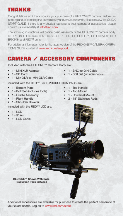
Included with the RED ONE™ Camera Body are:
• 1 - BNC-to-DIN Cable
• 1 - Bolt Set (includes tools)
• 1 - Mini XLR Adaptor
• 1 - SD Card
• 1 - Min-XLR-to-Mini-XLR Cable
Included with the RED™ BASE PRODUCTION PACK are:
• 1 - Bottom Plate
• 1 - Bolt Set (includes tools)
• 1 - Cradle Assembly
• 1 - Right Handle
• 1 - Shoulder Dovetail
Included with the RED™ LCD are:
• 1 - LCD
• 1 - 5” Arm
• 1 - LCD Cable
• 1 - Top Handle
• 1 - Top Mount
• 1 - Universal Mount
• 2 - 18” Stainless Rods
RED ONE™ Shown With Base
Production Pack Installed
Additional accessories are available for purchase to create the perfect camera to fit
your exact needs. Log on to www.red.com/store.
THANKSCAMERA / ACCESSORY COMPONENTS
The following instructions will outline basic assembly of the RED ONE™ camera body,
BASE PRODUCTION PACK, RED™ LCD, REDFLASH™, RED DRIVE®, and RED
BRICK®.
When connecting cables between camera and components, align Red dots
on cable and connector and press in firmly to establish a secure connection.
Wingnuts can be indexed by pulling out and rotating to desired position. This
may be necessary during assembly to clear components.
1. Remove your RED ONE™ camera body and all accessories from packaging and
place on a suitable work surface preferably in a dust-free environment.
2. Thoroughly inspect your camera and accessories.
• If there is any physical damage to your camera or accessories, please contact us
immediately at info@red.com.
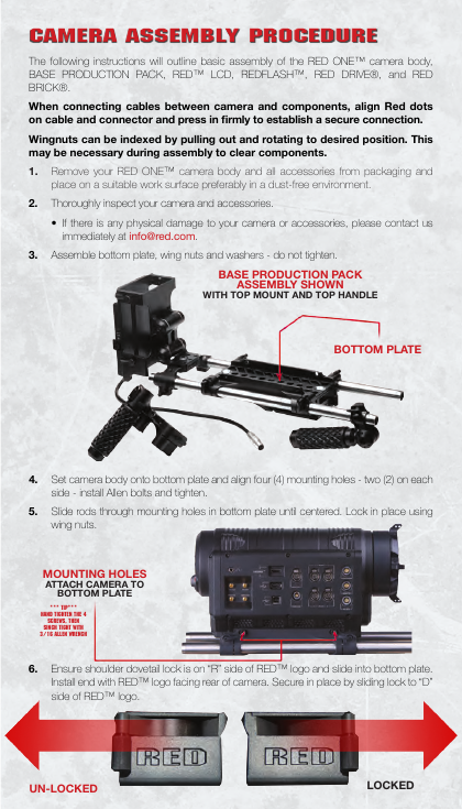
3. Assemble bottom plate, wing nuts and washers - do not tighten.
BASE PRODUCTION PACK
ASSEMBLY SHOWN
WITH TOP MOUNT AND TOP HANDLE
BOTTOM PLATE
4. Set camera body onto bottom plate and align four (4) mounting holes - two (2) on each
side - install Allen bolts and tighten.
5. Slide rods through mounting holes in bottom plate until centered. Lock in place using
wing nuts.
MOUNTING HOLES
ATTACH CAMERA TO
BOTTOM PLATE
*** TIP***
HAND TIGHTEN THE 4
SCREWS, THEN
SINCH TIGHT WITH
3/16 ALLEN WRENCH
6. Ensure shoulder dovetail lock is on “R” side of RED™ logo and slide into bottom plate.
Install end with RED™ logo facing rear of camera. Secure in place by sliding lock to “D”
side of RED™ logo.
UN-LOCKED
LOCKED
CAMERA ASSEMBLY PROCEDURE�
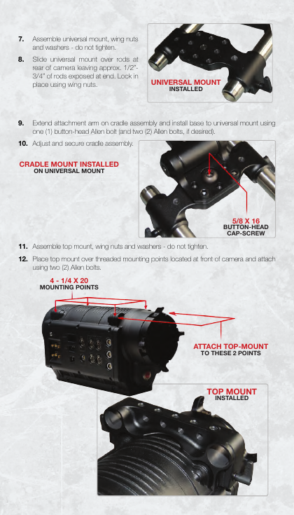
7. Assemble universal mount, wing nuts
and washers - do not tighten.
8. Slide universal mount over rods at
rear of camera leaving approx. 1/2”-
3/4” of rods exposed at end. Lock in
place using wing nuts.
UNIVERSAL MOUNT
INSTALLED
9. Extend attachment arm on cradle assembly and install base to universal mount using
one (1) button-head Allen bolt (and two (2) Allen bolts, if desired).
10. Adjust and secure cradle assembly.
CRADLE MOUNT INSTALLED
ON UNIVERSAL MOUNT
5/8 X 16
BUTTON-HEAD
CAP-SCREW
11. Assemble top mount, wing nuts and washers - do not tighten.
12. Place top mount over threaded mounting points located at front of camera and attach
using two (2) Allen bolts.
4 - 1/4 X 20
MOUNTING POINTS
ATTACH TOP-MOUNT
TO THESE 2 POINTS
TOP MOUNT
INSTALLED
�
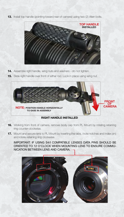
13. Install top handle (pointing toward rear of camera) using two (2) Allen bolts.
TOP HANDLE
INSTALLED
14. Assemble right handle, wing nuts and washers - do not tighten.
15. Slide right handle over front of either rod. Lock in place using wing nut.
NOTE: POSITION HANDLE HORIZONTALLY
TO EASE IN ASSEMBLY
RIGHT HANDLE INSTALLED
FRONT
OF
CAMERA
16. Working from front of camera, remove body cap from PL Mount by rotating retaining
ring counter-clockwise.
17. Mount and secure lens to PL Mount by inserting the tabs, (note notches and index pin)
and rotate retaining ring clockwise.
IMPORTANT: IF USING S4/I COMPATIBLE LENSES DATA PINS SHOULD BE
ORIENTED TO 12 O’CLOCK WHEN MOUNTING LENS TO ENSURE COMMU-
NICATION BETWEEN LENS AND CAMERA.
�
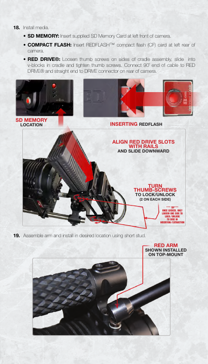
18. Install media.
• SD MEMORY: Insert supplied SD Memory Card at left front of camera.
• COMPACT FLASH: Insert REDFLASH™ compact flash (CF) card at left rear of
camera.
• RED DRIVE®: Loosen thumb screws on sides of cradle assembly, slide into
v-blocks in cradle and tighten thumb screws. Connect 90˚ end of cable to RED
DRIVE® and straight end to DRIVE connector on rear of camera.
SD MEMORY
LOCATION
INSERTING REDFLASH
ALIGN RED DRIVE SLOTS
WITH RAILS
AND SLIDE DOWNWARD
TURN
THUMB-SCREWS
TO LOCK/UNLOCK
(2 ON EACH SIDE)
*** TIP***
ONCE LOCKED, ONLY
LOOSEN ONE SIDE TO
LOCK/UNLOCK
TO EASE IN
INSERTION/EXTRACTION
19. Assemble arm and install in desired location using short stud.
RED ARM
SHOWN INSTALLED
ON TOP-MOUNT
�
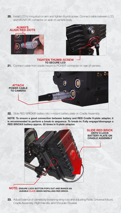
20. Install LCD to long stud on arm and tighten thumb screw. Connect cable between LCD
and MONITOR connector on side of camera body.
ALWAYS
ALIGN RED-DOTS
21. Connect cable from cradle mount to POWER connector on rear of camera.
TIGHTEN THUMB-SCREW
TO SECURE LCD
ATTACH
POWER CABLE
TO CAMERA
22. Slide RED BRICK® battery into v-mount battery plate on Cradle Assembly.
NOTE: To ensure a good connection between battery and RED Cradle V-plate adapter, it
is recommended to perform a break-in sequence. To break-in: Fully engage/disengage a
RED BRICK® battery approx. 20 times in V-plate adaptor.
SLIDE RED BRICK
ONTO V-LOCK
BATTERY PLATE ON
CRADLE ASSEMBLY
NOTE: ENSURE LOCK BUTTON POPS OUT AND MAKES AN
AUDIBLE CLICK WHEN INSTALLING RED BRICK.
23. Adjust balance of camera by loosening wing nuts and adjusting Rods, Universal Mount,
Cradle Assembly, Right Handle, and Shoulder Dovetail.
�
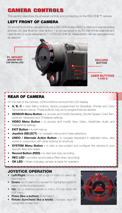
This section describes the physical controls and connectors on the RED ONE™ camera.
LEFT FRONT OF CAMERA
On the left front of the camera body are a RECORD button (RED) to start and stop recording
and two (2) User Buttons. User Button 1 is pre-assigned to AUTO WB (White balance) and
User Button 2 is pre-assigned to 1:1 FOCUS CHECK, these button can be reprogrammed
as desired.
PL MOUNT
(SHOWN WITH
CAP INSTALLED)
RECORD
BUTTON
USER BUTTONS
1 AND 2
REAR OF CAMERA
On the rear of the camera, control buttons surround the LCD display.
• A, B, C - User Menu buttons, factory programmed for Sensitivity, Shutter and Color
Temperature menus. These buttons may be re-programmed as desired
• SENSOR Menu Button - to access and modify Sensitivity, Shutter Speed, Color Tem-
perature, Varispeed and Timelapse settings
• VIDEO Menu Button - to access and modify View, Video, Viewfinder, Audio and
Headphone settings
• EXIT Button - to exit menus
• Joystick (SELECT) - to navigate menus and make selections
• UNDO / Alternate Action Button - to navigate backward in selected menu, also
works in conjunction with other buttons for shortcuts
• SYSTEM Menu Button - to start a new project and configure the camera to your
specific likes and needs
• Record Button (RED) - to start and stop recording
• REC LED - provides record status (Red when recording)
• OK LED - Green indicates camera is ready for operation
JOYSTICK OPERATION
• Left/Right: Moves to left or right in menu to select dif-
ferent items.
• Down: Go to next menu screen for highlighted option in
menu, similar to enter/select.
• Up: Go to previous screen in menu. If in top level, will
EXIT menu.
• Press (like a button): Enter/Select
• Rotate (turn/twist like a knob): Changes value on
highlighted screen box.
CAMERA CONTROLS�


 2023年江西萍乡中考道德与法治真题及答案.doc
 2012年重庆南川中考生物真题及答案.doc
 2013年江西师范大学地理学综合及文艺理论基础考研真题.doc
 2020年四川甘孜小升初语文真题及答案I卷.doc
 2020年注册岩土工程师专业基础考试真题及答案.doc
 2023-2024学年福建省厦门市九年级上学期数学月考试题及答案.doc
 2021-2022学年辽宁省沈阳市大东区九年级上学期语文期末试题及答案.doc
 2022-2023学年北京东城区初三第一学期物理期末试卷及答案.doc
 2018上半年江西教师资格初中地理学科知识与教学能力真题及答案.doc
 2012年河北国家公务员申论考试真题及答案-省级.doc
 2020-2021学年江苏省扬州市江都区邵樊片九年级上学期数学第一次质量检测试题及答案.doc
 2022下半年黑龙江教师资格证中学综合素质真题及答案.doc