GaN FET module performance
advantage over silicon
Narendra Mehta
Senior Systems Engineer, GaN products
High Voltage Power Solutions
Texas Instruments
�
Learn how GaN improves energy efficiency, power
density and solution size in next generation DC/DC
converters.
Gallium-nitride (GaN) FETs are increasingly finding use as next-generation, high-
power devices for power electronics systems [1]. GaN FETs can realize ultra-high-
power-density operation with low power loss due to high carrier mobility in the two-
dimensional electron gas (2DEG) channel, and high breakdown voltage due to large
critical electric field. GaN FETs are a majority carrier device, therefore, the absence of
reverse recovery charge creates a value proposition for high-voltage operation.
Introduction
All these characteristics are suitable for power
electronics applications featuring reduced power
loss under high-switching-frequency operation.
With GaN devices now being grown on affordable
silicon substrates, compared to GaN on sapphire or
bulk GaN, power GaN FETs will find an increasing
rate of adoption for highly efficient and form factor
constrained applications in the 30V and higher
DC/DC voltage conversion space. In this paper we
investigate the loss mechanisms in a hard-switched
DC/DC converter and how a GaN FET power stage
can outperform Si MOSFETs. In this paper we
compare a 80V GaN FET power stage to 80V Si
devices.
A GaN FET power stage device such as the
LMG5200 is an 80V GaN half-bridge power
module. This device integrates the driver and two
80V GaN FETs in a 6 mm x 8 mm QFN package,
optimized for extremely low-gate loop and power
loop impedance [2]. The inputs are 3V CMOS and
5V TTL logic compatible. Due to GaN’s intolerance
for excessive gate voltage, a proprietary clamping
technique ensures that the gate voltage of the GaN
FETs is always below the allowed limit. This device
extends the advantage of discrete GaN FETs by
offering a user-friendly package, which is easy to
layout and assemble into the final product.
The LMG5200 meets the IPC-2221B and the IEC
60950 pollution degree 1 clearance and creepage
requirements without any need for underfill. This is
because the minimum spacing between high-
and low-voltage pins is greater than 0.5 mm. This
eliminates the need for boards to be manufactured
with underfill and greatly simplifies board design
and reduces cost. The pin-out also eliminates the
need for a via-in-pad design as there is adequate
spacing between the power pins for via placement.
Additionally, this helps in to reduce board complexity
and cost (Figure 1).
HS
3
HB
2
HI
LI
4
5
LMG5200
6
7
VCC AGND
Figure 1. Top-down view of a GaN FET power
stage device, showing pin-out.
1
VIN
9
8
PGND
SW
GaN FET module performance advantage over silicon
2
Texas Instruments: March 2015
�
DC/DC converter losses
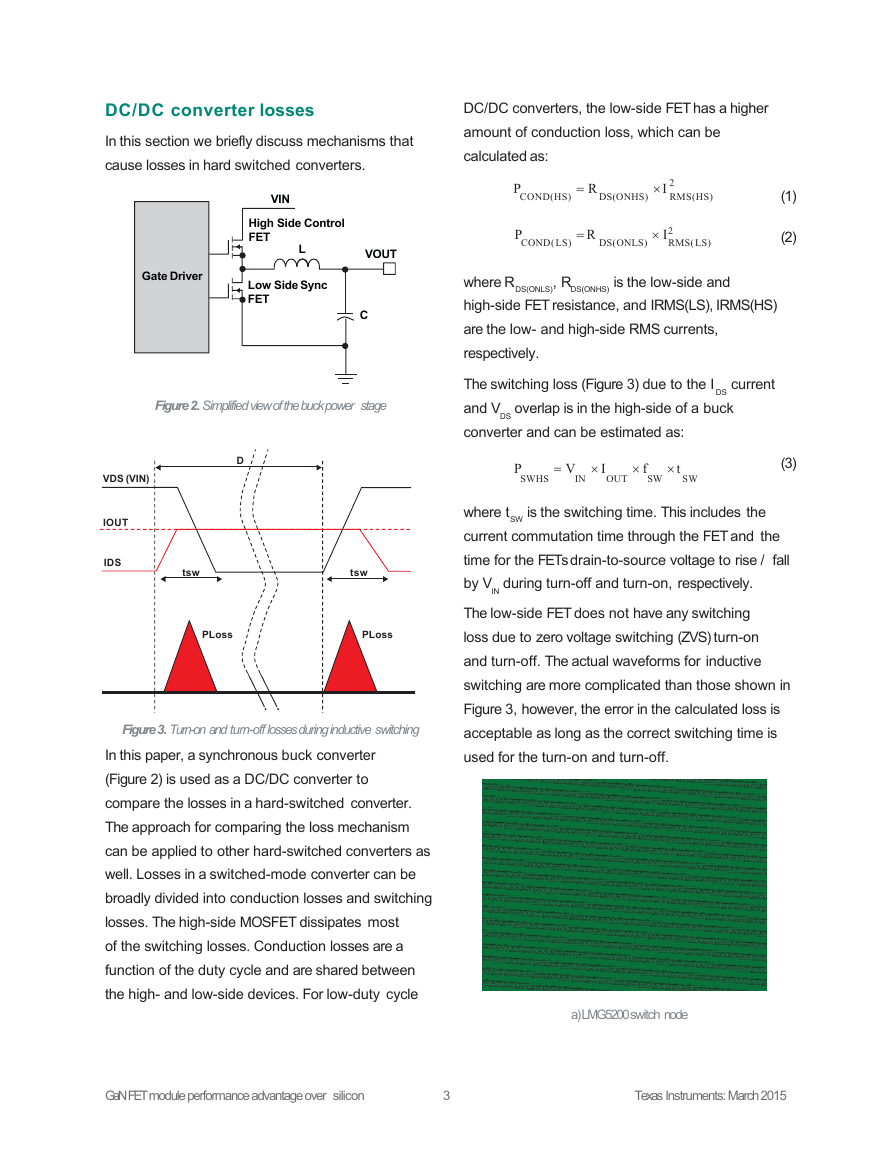
In this section we briefly discuss mechanisms that
cause losses in hard switched converters.
DC/DC converters, the low-side FET has a higher
amount of conduction loss, which can be
calculated as:
VIN
High Side Control
FET
L
VOUT
Low Side Sync
FET
C
Gate Driver
Figure 2. Simplified view of the buck power stage
P
COND(HS)
R
DS(ONHS)
I
2
RMS(HS)
P
COND(LS)
R
DS(ONLS)
I2
RMS(LS)
(1)
(2)
, R
DS(ONHS)
is the low-side and
where RDS(ONLS)
high-side FET resistance, and IRMS(LS), IRMS(HS)
are the low- and high-side RMS currents,
respectively.
The switching loss (Figure 3) due to the I
DS
and V overlap is in the high-side of a buck
converter and can be estimated as:
DS
current
D
P
SWHS
V I
IN
OUT
f
SW
t
SW
(3)
IN
SW
is the switching time. This includes the
where t
current commutation time through the FET and the
time for the FETs drain-to-source voltage to rise / fall
by V during turn-off and turn-on, respectively.
The low-side FET does not have any switching
loss due to zero voltage switching (ZVS) turn-on
and turn-off. The actual waveforms for inductive
switching are more complicated than those shown in
Figure 3, however, the error in the calculated loss is
acceptable as long as the correct switching time is
used for the turn-on and turn-off.
VDS (VIN)
IOUT
IDS
tsw
tsw
PLoss
PLoss
Figure 3. Turn-on and turn-off losses during inductive switching
In this paper, a synchronous buck converter
(Figure 2) is used as a DC/DC converter to
compare the losses in a hard-switched converter.
The approach for comparing the loss mechanism
can be applied to other hard-switched converters as
well. Losses in a switched-mode converter can be
broadly divided into conduction losses and switching
losses. The high-side MOSFET dissipates most
of the switching losses. Conduction losses are a
function of the duty cycle and are shared between
the high- and low-side devices. For low-duty cycle
a) LMG5200 switch node
GaN FET module performance advantage over silicon
3
Texas Instruments: March 2015
�
P
RR
fsw •Q
•V
IN
RR
(4)
Because GaN is a majority carrier device, it does not
have reverse recovery-based losses.
The body diode of the low-side MOSFET conducts
during dead time. This causes a power loss in the
diode associated with the forward voltage of the
diode. GaN has a higher third quadrant conduction
voltage (V of 2V at 10A for LMG5200) compared
to ~1V for Si FETs. Hence, the GaN device exhibits
a higher power loss during dead time. It is critical
to ensure that the dead time is small in order to
minimize this loss [4]. The power loss associated
with the body diode can be calculated as:
SD
P
BD
fsw •V •I
SD
OUT
• T
DEADON
T
DEADOFF
(5)
The energy stored in the output capacitance of the
MOSFETs is dissipated during turn-on. Since the
output capacitance is a strong function of the drain-
to-source voltage, the proper way to calculate this
power loss PCAP is:
P
CAP
fsw •Q
OSS(VIN )
•V
IN
(6)
OSS(VIN)
where Q
is the output charge of the MOSFET,
evaluated at the input voltage. GaN devices, due to
their small output capacitance for the same RDSON
compared to Si, exhibit a much smaller PCAP loss
as well.
Gate driver losses are another contributor to
switching loss. A detailed explanation of losses
associated with the gate driver can be found in the
LM5113 application report [5].
Besides the active device-related losses in a hard-
switched buck converter discussed in this paper,
b) Si7852DP 80v FET SW node
Figure 4. Comparison of a GaN FET power stage
switch-node to silicon switch-node voltage waveform
The device construction of GaN allows very short,
switching times due to small gate and output
capacitance for the same RDSON. As noted in
Figure 4, switching time for the GaN FET power
stage is less than 1 ns compared to 6 ns for a
Si FET with a comparable breakdown voltage
(Si7852DP).
Faster switching edges means the switching
losses are significantly lowered in the GaN module
compared to the Si MOSFET-based buck converter.
Also note that there is minimal overshoot in the GaN
FET power stage switch-node waveforms due to an
extremely small (<300 pH) power loop inductance.
The gate loop and common source inductance
are also minimized in the GaN FET power stage
package to be below 200 pH. High parasitic
inductance in these loops can cause a significant
power loss [3].
Besides the high-side turn-on and turn-off losses,
forced commutation of the low-side MOSFETs
body diode is a significant source of switching loss
in high-voltage DC/DC converters. This loss is
primarily due to the reverse recovery charge (QRR)
in the freewheeling low-side FET. The power loss
due to reverse recovery is given by:
GaN FET module performance advantage over silicon
4
Texas Instruments: March 2015
�
there are losses associated with the inductor. These
losses include core loss and AC- and DC-winding
loss, which also should be taken into account when
calculating system efficiency [6, 7].
Efficiency improvements
compared to Si
Efficiency vs. Load Current
y
c
n
e
i
c
i
f
f
E
96
94
92
90
88
86
84
82
80
LMG5200, 80V, 1MHz
Si 80V MOSFET, 250kHz
Si, 80V MOSFET, 800kHz
1
2
3
4
5
6
Current (A)
7
8
9
10
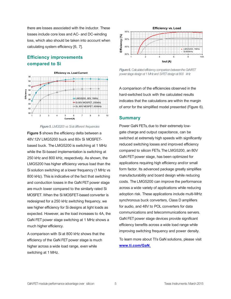
Figure 5. LMG5200 vs Si at different frequencies
Figure 5 shows the efficiency delta between a
48V:12V LMG5200 buck and 80v Si MOSFET-
based buck. The LMG5200 is switching at 1 MHz
while the Si-based implementation is switching at
250 kHz and 800 kHz, respectively. As shown, the
LMG5200 has higher efficiency versus load than the
Si solution switching at a lower frequency (1 MHz vs
800 kHz). This is indicative of the fact that switching
and conduction losses in the GaN FET power stage
are much lower compared to the similarly rated Si
MOSFET. When the Si MOSFET-based converter is
redesigned for a 250 kHz switching frequency, we
see higher efficiency for Si designs at light loads as
expected. However, as the load increases to 4A, the
GaN FET power stage switching at 1 MHz shows a
much higher efficiency.
A comparison with Si at 800 kHz shows that the
efficiency of the GaN FET power stage is much
higher across a wide load range, even while
switching at 1 MHz.
)
%
(
y
c
n
e
c
i
f
f
i
E
95%
90%
85%
80%
1
Efficiency vs. Load
LMG5200, 1MHz
Si 800kHz
2
4
6
8
10A
Iout (A)
Figure 6. Calculated efficiency comparison between the GaN FET
power stage design at 1 MHz and Si FET design at 800 kHz
A comparison of the efficiencies observed in the
hard-switched buck with the calculated results
indicates that the calculations are within the margin
of error for the simplified model presented (Figure 6).
Summary
Power GaN FETs, due to their extremely low-
gate charge and output capacitance, can be
switched at extremely high speeds with significantly
reduced switching losses and improved efficiency
compared to silicon FETs. The LMG5200, an 80V
GaN FET power stage, has been optimized for
applications requiring high efficiency and/or small
form factor. Its advanced package greatly simplifies
manufacturability and board design while reducing
costs. The LMG5200 can improve the performance
across a wide variety of applications while reducing
adoption risk. These applications include multi-MHz
synchronous buck converters, Class D amplifiers
for audio, and 48V to POL converters for data
communications and telecommunications servers.
GaN FET power stage devices provide significant
efficiency benefits across a wide load range while
improving switching frequency and power density.
To learn more about TI’s GaN solutions, please visit
www.ti.com/GaN.
GaN FET module performance advantage over silicon
5
Texas Instruments: March 2015
�
References
1. Lidow, A. Integrated Power Electronics Systems (CIPS),
2010 6th International Conference, 2010
2. LMG5200 datasheet
3. David Jauregui, Bo Wang, and Rengang Chen.
Power Loss Calculation With Common Source Inductance
Consideration for Synchronous Buck Converters, Application
Report (SLPA009A), Texas Instruments, July 2011
4. Di Han; Sarlioglu, B. Wide Bandgap Power Devices and
Applications (WiPDA), 2014 IEEE Workshop on DOI:
10.1109/WiPDA.2014.6964627
5. Narendra Mehta, Design Considerations for LM5113
Advanced GaN FET Driver During High-Frequency Operation,
Application Report (SNVA723), Texas Instruments,
November 2014
6. Reinert, J.; Brockmeyer, A.; De Doncker, R.W.A.A.
Calculation of losses in ferro- and ferrimagnetic materials
based on the modified Steinmetz equation, Industry
Applications, IEEE Transactions on Volume: 37 , Issue: 4
7. Jieli Li; Abdallah, T.; Sullivan, C.R. Improved calculation of core
loss with nonsinusoidal waveforms, Industry Applications
Conference, 2001. Thirty-Sixth IAS Annual Meeting.
Conference Record of the 2001 IEEE Volume: 4
Important Notice: The products and services of Texas Instruments Incorporated and its subsidiaries described herein are sold subject to TI’s standard terms
and conditions of sale. Customers are advised to obtain the most current and complete information about TI products and services before placing orders. TI
assumes no liability for applications assistance, customer’s applications or product designs, software performance, or infringement of patents. The
publication of information regarding any other company’s products or services does not constitute TI’s approval, warranty or endorsement thereof.
The platform bar is a trademark of Texas Instruments.
All other trademarks are the property of their respective owners.
© 2015 Texas Instruments Incorporated
SLYY071
�
IMPORTANT NOTICE
Texas Instruments Incorporated and its subsidiaries (TI) reserve the right to make corrections, enhancements, improvements and other
changes to its semiconductor products and services per JESD46, latest issue, and to discontinue any product or service per JESD48, latest
issue. Buyers should obtain the latest relevant information before placing orders and should verify that such information is current and
complete. All semiconductor products (also referred to herein as “components”) are sold subject to TI’s terms and conditions of sale
supplied at the time of order acknowledgment.
TI warrants performance of its components to the specifications applicable at the time of sale, in accordance with the warranty in TI’s terms
and conditions of sale of semiconductor products. Testing and other quality control techniques are used to the extent TI deems necessary
to support this warranty. Except where mandated by applicable law, testing of all parameters of each component is not necessarily
performed.
TI assumes no liability for applications assistance or the design of Buyers’ products. Buyers are responsible for their products and
applications using TI components. To minimize the risks associated with Buyers’ products and applications, Buyers should provide
adequate design and operating safeguards.
TI does not warrant or represent that any license, either express or implied, is granted under any patent right, copyright, mask work right, or
other intellectual property right relating to any combination, machine, or process in which TI components or services are used. Information
published by TI regarding third-party products or services does not constitute a license to use such products or services or a warranty or
endorsement thereof. Use of such information may require a license from a third party under the patents or other intellectual property of the
third party, or a license from TI under the patents or other intellectual property of TI.
Reproduction of significant portions of TI information in TI data books or data sheets is permissible only if reproduction is without alteration
and is accompanied by all associated warranties, conditions, limitations, and notices. TI is not responsible or liable for such altered
documentation. Information of third parties may be subject to additional restrictions.
Resale of TI components or services with statements different from or beyond the parameters stated by TI for that component or service
voids all express and any implied warranties for the associated TI component or service and is an unfair and deceptive business practice.
TI is not responsible or liable for any such statements.
Buyer acknowledges and agrees that it is solely responsible for compliance with all legal, regulatory and safety-related requirements
concerning its products, and any use of TI components in its applications, notwithstanding any applications-related information or support
that may be provided by TI. Buyer represents and agrees that it has all the necessary expertise to create and implement safeguards which
anticipate dangerous consequences of failures, monitor failures and their consequences, lessen the likelihood of failures that might cause
harm and take appropriate remedial actions. Buyer will fully indemnify TI and its representatives against any damages arising out of the use
of any TI components in safety-critical applications.
In some cases, TI components may be promoted specifically to facilitate safety-related applications. With such components, TI’s goal is to
help enable customers to design and create their own end-product solutions that meet applicable functional safety standards and
requirements. Nonetheless, such components are subject to these terms.
No TI components are authorized for use in FDA Class III (or similar life-critical medical equipment) unless authorized officers of the parties
have executed a special agreement specifically governing such use.
Only those TI components which TI has specifically designated as military grade or “enhanced plastic” are designed and intended for use in
military/aerospace applications or environments. Buyer acknowledges and agrees that any military or aerospace use of TI components
which have not been so designated is solely at the Buyer's risk, and that Buyer is solely responsible for compliance with all legal and
regulatory requirements in connection with such use.
TI has specifically designated certain components as meeting ISO/TS16949 requirements, mainly for automotive use. In any case of use of
non-designated products, TI will not be responsible for any failure to meet ISO/TS16949.
Products
Audio
Amplifiers
Data Converters
DLP® Products
DSP
Clocks and Timers
Interface
Logic
Power Mgmt
Microcontrollers
RFID
OMAP Applications Processors
Wireless Connectivity
Applications
Automotive and Transportation
Communications and Telecom www.ti.com/communications
Computers and Peripherals
Consumer Electronics
Energy and Lighting
Industrial
Medical
Security
Space, Avionics and Defense
Video and Imaging
www.ti.com/audio
amplifier.ti.com
dataconverter.ti.com
www.dlp.com
dsp.ti.com
www.ti.com/clocks
interface.ti.com
logic.ti.com
power.ti.com
microcontroller.ti.com
www.ti-rfid.com
www.ti.com/omap
www.ti.com/wirelessconnectivity
TI E2E Community
e2e.ti.com
www.ti.com/automotive
www.ti.com/computers
www.ti.com/consumer-apps
www.ti.com/energy
www.ti.com/industrial
www.ti.com/medical
www.ti.com/security
www.ti.com/space-avionics-defense
www.ti.com/video
Mailing Address: Texas Instruments, Post Office Box 655303, Dallas, Texas 75265
Copyright © 2015, Texas Instruments Incorporated
�




 2023年江西萍乡中考道德与法治真题及答案.doc
 2012年重庆南川中考生物真题及答案.doc
 2013年江西师范大学地理学综合及文艺理论基础考研真题.doc
 2020年四川甘孜小升初语文真题及答案I卷.doc
 2020年注册岩土工程师专业基础考试真题及答案.doc
 2023-2024学年福建省厦门市九年级上学期数学月考试题及答案.doc
 2021-2022学年辽宁省沈阳市大东区九年级上学期语文期末试题及答案.doc
 2022-2023学年北京东城区初三第一学期物理期末试卷及答案.doc
 2018上半年江西教师资格初中地理学科知识与教学能力真题及答案.doc
 2012年河北国家公务员申论考试真题及答案-省级.doc
 2020-2021学年江苏省扬州市江都区邵樊片九年级上学期数学第一次质量检测试题及答案.doc
 2022下半年黑龙江教师资格证中学综合素质真题及答案.doc