DM9000CI
Industrial-grade Ethernet Controller with General Processor Interface
Support QQ 1547311723 Duoduo
DAVICOM Semiconductor, Inc.
DM9000CI
Industrial-grade Ethernet Controller
With General Processor Interface
DATA SHEET
Preliminary
Version: DM9000CI-DS-P01
June 5, 2009
Preliminary
Version: DM9000CI-13-DS-P01
June 5, 2009
1
�
DM9000CI
Industrial-grade Ethernet Controller with General Processor Interface
Content
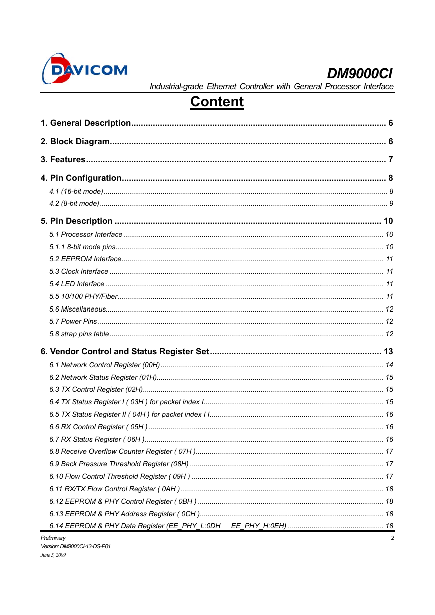
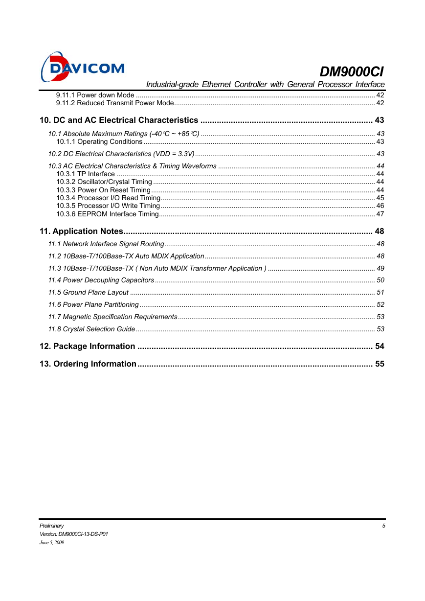
1. General Description........................................................................................................... 6
2. Block Diagram.................................................................................................................... 6
3. Features.............................................................................................................................. 7
4. Pin Configuration............................................................................................................... 8
4.1 (16-bit mode)................................................................................................................................................. 8
4.2 (8-bit mode)................................................................................................................................................... 9
5. Pin Description ................................................................................................................ 10
5.1 Processor Interface ..................................................................................................................................... 10
5.1.1 8-bit mode pins......................................................................................................................................... 10
5.2 EEPROM Interface...................................................................................................................................... 11
5.3 Clock Interface ............................................................................................................................................ 11
5.4 LED Interface .............................................................................................................................................. 11
5.5 10/100 PHY/Fiber........................................................................................................................................ 11
5.6 Miscellaneous.............................................................................................................................................. 12
5.7 Power Pins .................................................................................................................................................. 12
5.8 strap pins table............................................................................................................................................ 12
6. Vendor Control and Status Register Set........................................................................ 13
6.1 Network Control Register (00H).................................................................................................................. 14
6.2 Network Status Register (01H).................................................................................................................... 15
6.3 TX Control Register (02H)........................................................................................................................... 15
6.4 TX Status Register I ( 03H ) for packet index I............................................................................................ 15
6.5 TX Status Register II ( 04H ) for packet index I I......................................................................................... 16
6.6 RX Control Register ( 05H ) ........................................................................................................................ 16
6.7 RX Status Register ( 06H ).......................................................................................................................... 16
6.8 Receive Overflow Counter Register ( 07H )................................................................................................ 17
6.9 Back Pressure Threshold Register (08H) ................................................................................................... 17
6.10 Flow Control Threshold Register ( 09H ) .................................................................................................. 17
6.11 RX/TX Flow Control Register ( 0AH )........................................................................................................ 18
6.12 EEPROM & PHY Control Register ( 0BH ) ............................................................................................... 18
6.13 EEPROM & PHY Address Register ( 0CH ).............................................................................................. 18
6.14 EEPROM & PHY Data Register (EE_PHY_L:0DH EE_PHY_H:0EH) ................................................. 18
2
Preliminary
Version: DM9000CI-13-DS-P01
June 5, 2009
�
DM9000CI
Industrial-grade Ethernet Controller with General Processor Interface
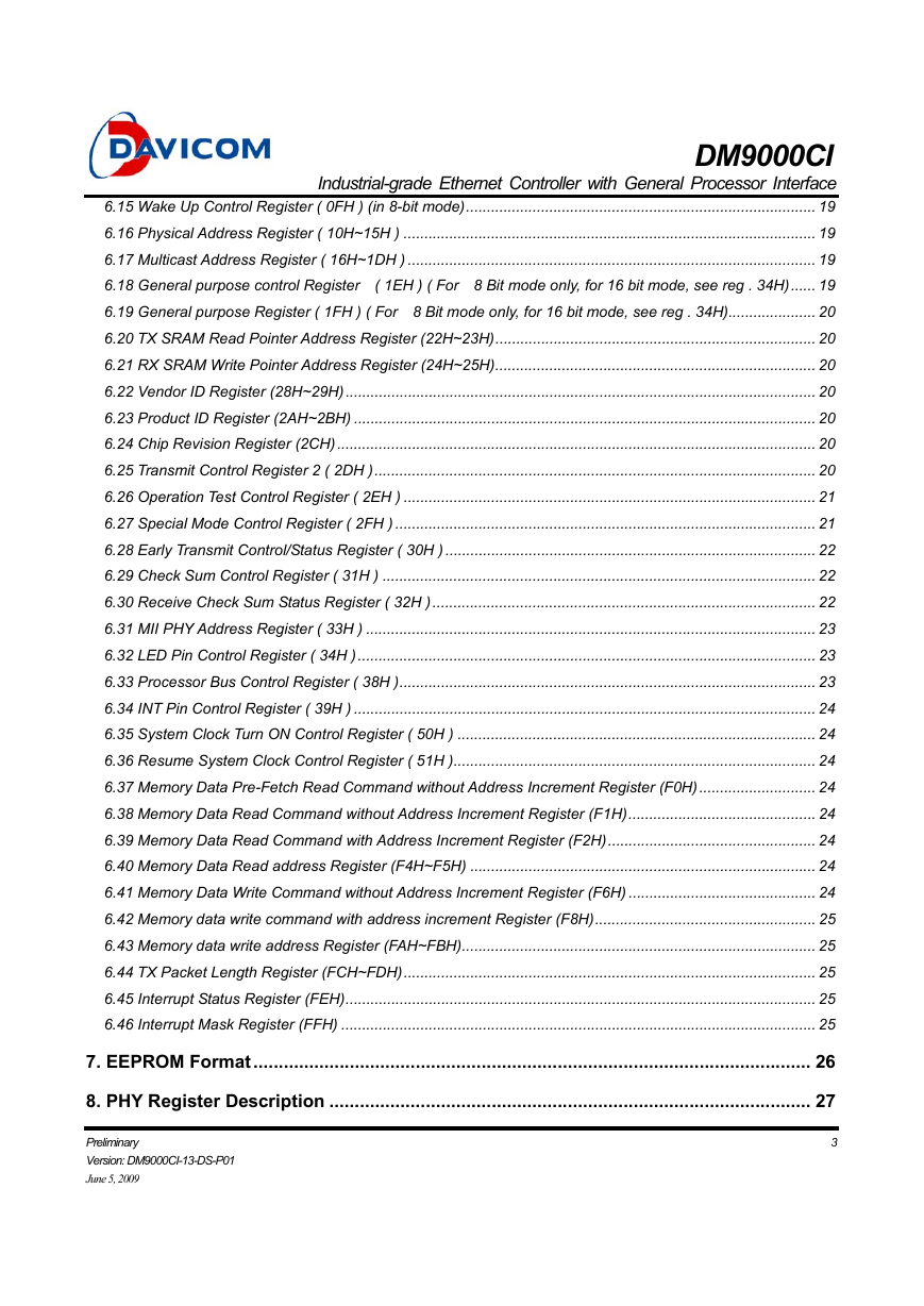
6.15 Wake Up Control Register ( 0FH ) (in 8-bit mode).................................................................................... 19
6.16 Physical Address Register ( 10H~15H ) ................................................................................................... 19
6.17 Multicast Address Register ( 16H~1DH ) .................................................................................................. 19
6.18 General purpose control Register ( 1EH ) ( For 8 Bit mode only, for 16 bit mode, see reg . 34H)...... 19
6.19 General purpose Register ( 1FH ) ( For 8 Bit mode only, for 16 bit mode, see reg . 34H)..................... 20
6.20 TX SRAM Read Pointer Address Register (22H~23H)............................................................................. 20
6.21 RX SRAM Write Pointer Address Register (24H~25H)............................................................................. 20
6.22 Vendor ID Register (28H~29H)................................................................................................................. 20
6.23 Product ID Register (2AH~2BH) ............................................................................................................... 20
6.24 Chip Revision Register (2CH)................................................................................................................... 20
6.25 Transmit Control Register 2 ( 2DH ).......................................................................................................... 20
6.26 Operation Test Control Register ( 2EH ) ................................................................................................... 21
6.27 Special Mode Control Register ( 2FH ) ..................................................................................................... 21
6.28 Early Transmit Control/Status Register ( 30H ) ......................................................................................... 22
6.29 Check Sum Control Register ( 31H ) ........................................................................................................ 22
6.30 Receive Check Sum Status Register ( 32H )............................................................................................ 22
6.31 MII PHY Address Register ( 33H ) ............................................................................................................ 23
6.32 LED Pin Control Register ( 34H ).............................................................................................................. 23
6.33 Processor Bus Control Register ( 38H ).................................................................................................... 23
6.34 INT Pin Control Register ( 39H ) ............................................................................................................... 24
6.35 System Clock Turn ON Control Register ( 50H ) ...................................................................................... 24
6.36 Resume System Clock Control Register ( 51H )....................................................................................... 24
6.37 Memory Data Pre-Fetch Read Command without Address Increment Register (F0H)............................ 24
6.38 Memory Data Read Command without Address Increment Register (F1H)............................................. 24
6.39 Memory Data Read Command with Address Increment Register (F2H).................................................. 24
6.40 Memory Data Read address Register (F4H~F5H) ................................................................................... 24
6.41 Memory Data Write Command without Address Increment Register (F6H) ............................................. 24
6.42 Memory data write command with address increment Register (F8H)..................................................... 25
6.43 Memory data write address Register (FAH~FBH)..................................................................................... 25
6.44 TX Packet Length Register (FCH~FDH)................................................................................................... 25
6.45 Interrupt Status Register (FEH)................................................................................................................. 25
6.46 Interrupt Mask Register (FFH) .................................................................................................................. 25
7. EEPROM Format.............................................................................................................. 26
8. PHY Register Description ............................................................................................... 27
Preliminary
Version: DM9000CI-13-DS-P01
June 5, 2009
3
�
DM9000CI
Industrial-grade Ethernet Controller with General Processor Interface
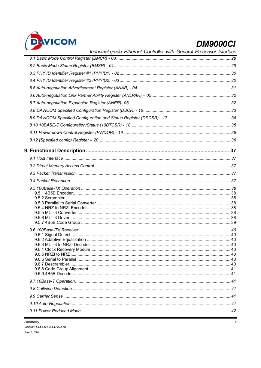
8.1 Basic Mode Control Register (BMCR) - 00 ................................................................................................. 28
8.2 Basic Mode Status Register (BMSR) - 01................................................................................................... 29
8.3 PHY ID Identifier Register #1 (PHYID1) - 02 .............................................................................................. 30
8.4 PHY ID Identifier Register #2 (PHYID2) - 03 .............................................................................................. 30
8.5 Auto-negotiation Advertisement Register (ANAR) - 04............................................................................... 31
8.6 Auto-negotiation Link Partner Ability Register (ANLPAR) – 05................................................................... 32
8.7 Auto-negotiation Expansion Register (ANER)- 06 ...................................................................................... 32
8.8 DAVICOM Specified Configuration Register (DSCR) - 16.......................................................................... 33
8.9 DAVICOM Specified Configuration and Status Register (DSCSR) - 17 ..................................................... 34
8.10 10BASE-T Configuration/Status (10BTCSR) - 18..................................................................................... 35
8.11 Power down Control Register (PWDOR) - 19 ........................................................................................... 36
8.12 (Specified config) Register – 20................................................................................................................ 36
9. Functional Description.................................................................................................... 37
9.1 Host Interface.............................................................................................................................................. 37
9.2 Direct Memory Access Control.................................................................................................................... 37
9.3 Packet Transmission ................................................................................................................................... 37
9.4 Packet Reception ........................................................................................................................................ 37
9.5 100Base-TX Operation ............................................................................................................................... 38
9.5.1 4B5B Encoder...................................................................................................................................... 38
9.5.2 Scrambler............................................................................................................................................. 38
9.5.3 Parallel to Serial Converter.................................................................................................................. 38
9.5.4 NRZ to NRZI Encoder.......................................................................................................................... 38
9.5.5 MLT-3 Converter .................................................................................................................................. 38
9.5.6 MLT-3 Driver ........................................................................................................................................ 38
9.5.7 4B5B Code Group ............................................................................................................................... 39
9.6 100Base-TX Receiver ................................................................................................................................. 40
9.6.1 Signal Detect........................................................................................................................................ 40
9.6.2 Adaptive Equalization .......................................................................................................................... 40
9.6.3 MLT-3 to NRZI Decoder....................................................................................................................... 40
9.6.4 Clock Recovery Module....................................................................................................................... 40
9.6.5 NRZI to NRZ ........................................................................................................................................ 40
9.6.6 Serial to Parallel................................................................................................................................... 40
9.6.7 Descrambler......................................................................................................................................... 40
9.6.8 Code Group Alignment ........................................................................................................................ 41
9.6.9 4B5B Decoder...................................................................................................................................... 41
9.7 10Base-T Operation.................................................................................................................................... 41
9.8 Collision Detection ...................................................................................................................................... 41
9.9 Carrier Sense .............................................................................................................................................. 41
9.10 Auto-Negotiation........................................................................................................................................ 41
9.11 Power Reduced Mode............................................................................................................................... 42
Preliminary
Version: DM9000CI-13-DS-P01
June 5, 2009
4
�
DM9000CI
Industrial-grade Ethernet Controller with General Processor Interface
9.11.1 Power down Mode ............................................................................................................................. 42
9.11.2 Reduced Transmit Power Mode......................................................................................................... 42
10. DC and AC Electrical Characteristics .......................................................................... 43
10.1 Absolute Maximum Ratings (-40°C ~ +85°C) ........................................................................................... 43
10.1.1 Operating Conditions ......................................................................................................................... 43
10.2 DC Electrical Characteristics (VDD = 3.3V).............................................................................................. 43
10.3 AC Electrical Characteristics & Timing Waveforms .................................................................................. 44
10.3.1 TP Interface ....................................................................................................................................... 44
10.3.2 Oscillator/Crystal Timing .................................................................................................................... 44
10.3.3 Power On Reset Timing..................................................................................................................... 44
10.3.4 Processor I/O Read Timing................................................................................................................ 45
10.3.5 Processor I/O Write Timing................................................................................................................ 46
10.3.6 EEPROM Interface Timing................................................................................................................. 47
11. Application Notes........................................................................................................... 48
11.1 Network Interface Signal Routing.............................................................................................................. 48
11.2 10Base-T/100Base-TX Auto MDIX Application......................................................................................... 48
11.3 10Base-T/100Base-TX ( Non Auto MDIX Transformer Application ) ........................................................ 49
11.4 Power Decoupling Capacitors ................................................................................................................... 50
11.5 Ground Plane Layout ................................................................................................................................ 51
11.6 Power Plane Partitioning ........................................................................................................................... 52
11.7 Magnetic Specification Requirements....................................................................................................... 53
11.8 Crystal Selection Guide............................................................................................................................. 53
12. Package Information ..................................................................................................... 54
13. Ordering Information..................................................................................................... 55
Preliminary
Version: DM9000CI-13-DS-P01
June 5, 2009
5
�
DM9000CI
Industrial-grade Ethernet Controller with General Processor Interface
1. General Description
The DM9000CI is a fully integrated and cost-effective
Industrial-grade
low pin count single chip Fast
Ethernet controller with a general processor interface,
a 10/100M PHY and 4K Dword SRAM. It is designed
with
low power and high performance process
interface that support 3.3V with 5V IO tolerance.
The DM9000CI supports 8-bit and 16-bit data
interfaces to internal memory accesses for various
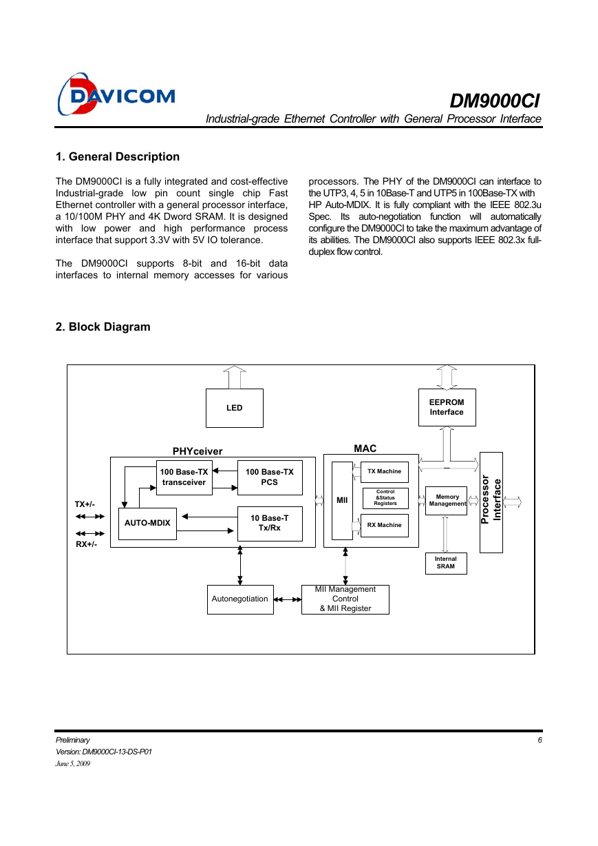
2. Block Diagram
Its auto-negotiation
processors. The PHY of the DM9000CI can interface to
the UTP3, 4, 5 in 10Base-T and UTP5 in 100Base-TX with
HP Auto-MDIX. It is fully compliant with the IEEE 802.3u
Spec.
function will automatically
configure the DM9000CI to take the maximum advantage of
its abilities. The DM9000CI also supports IEEE 802.3x full-
duplex flow control.
LED
EEPROM
Interface
PHYceiver
100 Base-TX
transceiver
100 Base-TX
PCS
MAC
TX Machine
MII
Control
&Status
Registers
Memory
Management
AUTO-MDIX
10 Base-T
Tx/Rx
RX Machine
Internal
SRAM
r
o
s
s
e
c
o
r
P
e
c
a
f
r
e
t
n
I
MII Management
Control
& MII Register
Autonegotiation
6
TX+/-
RX+/-
Preliminary
Version: DM9000CI-13-DS-P01
June 5, 2009
�
DM9000CI
Industrial-grade Ethernet Controller with General Processor Interface
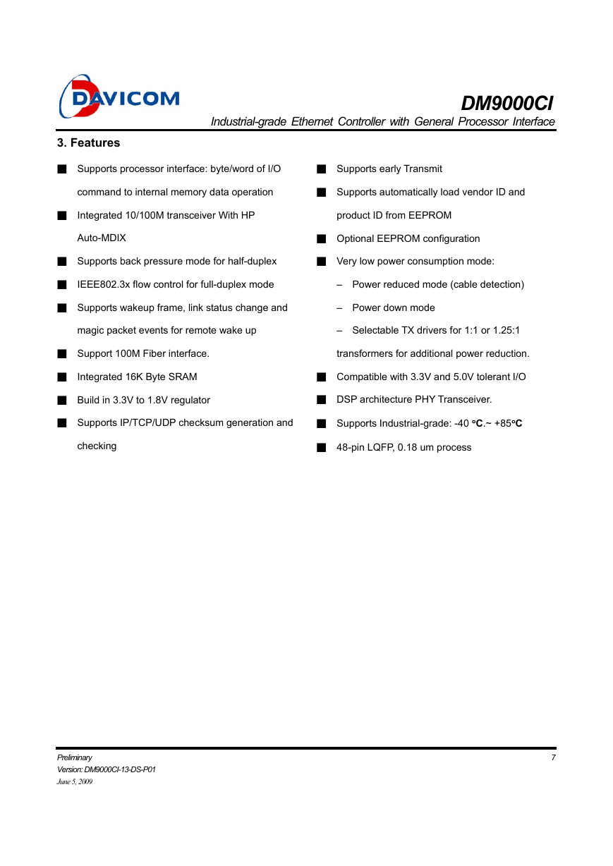
3. Features
■ Supports processor interface: byte/word of I/O
■ Supports early Transmit
command to internal memory data operation
■ Supports automatically load vendor ID and
■
Integrated 10/100M transceiver With HP
product ID from EEPROM
Auto-MDIX
■ Supports back pressure mode for half-duplex
■ Optional EEPROM configuration
■ Very low power consumption mode:
■
IEEE802.3x flow control for full-duplex mode
– Power reduced mode (cable detection)
■ Supports wakeup frame, link status change and
– Power down mode
magic packet events for remote wake up
– Selectable TX drivers for 1:1 or 1.25:1
■ Support 100M Fiber interface.
transformers for additional power reduction.
■
Integrated 16K Byte SRAM
■ Compatible with 3.3V and 5.0V tolerant I/O
■ Build in 3.3V to 1.8V regulator
■ DSP architecture PHY Transceiver.
■ Supports IP/TCP/UDP checksum generation and
■ Supports Industrial-grade: -40 °C.~ +85°C
checking
■ 48-pin LQFP, 0.18 um process
Preliminary
Version: DM9000CI-13-DS-P01
June 5, 2009
7
�
DM9000CI
Industrial-grade Ethernet Controller with General Processor Interface
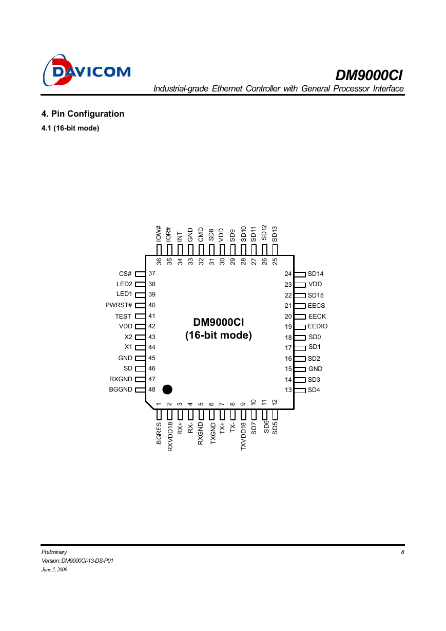
4. Pin Configuration
4.1 (16-bit mode)
#
W
O
I
#
R
O
I
D
N
G
D
M
C
8
D
S
D
D
V
9
D
S
T
N
I
0
1
D
S
1
1
D
S
2
1
D
S
3
1
D
S
6
3
5
3
4
3
3
3
2
3
1
3
0
3
9
2
8
2
7
2
6
2
5
2
CS#
LED2
LED1
PWRST#
TEST
VDD
X2
X1
GND
SD
RXGND
BGGND
37
38
39
40
41
42
43
44
45
46
47
48
DM9000CI
(16-bit mode)
24
23
22
21
20
19
18
17
16
15
14
13
SD14
VDD
SD15
EECS
EECK
EEDIO
SD0
SD1
SD2
GND
SD3
SD4
0
1 2 3 4 5 6 7 8 9 1
1
1
2
1
S
E
R
G
B
8
1
D
D
V
X
R
+
X
R
-
X
R
+
X
T
-
X
T
D
N
G
X
R
D
N
G
X
T
8
1
D
D
V
X
T
7
D
S
6
D
S
5
D
S
Preliminary
Version: DM9000CI-13-DS-P01
June 5, 2009
8
�


 2023年江西萍乡中考道德与法治真题及答案.doc
 2012年重庆南川中考生物真题及答案.doc
 2013年江西师范大学地理学综合及文艺理论基础考研真题.doc
 2020年四川甘孜小升初语文真题及答案I卷.doc
 2020年注册岩土工程师专业基础考试真题及答案.doc
 2023-2024学年福建省厦门市九年级上学期数学月考试题及答案.doc
 2021-2022学年辽宁省沈阳市大东区九年级上学期语文期末试题及答案.doc
 2022-2023学年北京东城区初三第一学期物理期末试卷及答案.doc
 2018上半年江西教师资格初中地理学科知识与教学能力真题及答案.doc
 2012年河北国家公务员申论考试真题及答案-省级.doc
 2020-2021学年江苏省扬州市江都区邵樊片九年级上学期数学第一次质量检测试题及答案.doc
 2022下半年黑龙江教师资格证中学综合素质真题及答案.doc