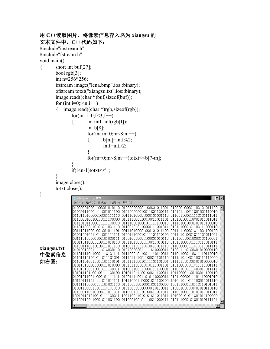
用 C++读取图片,将像素信息存入名为 xiangsu 的
文本文件中,C++代码如下:
#include"iostream.h"
#include"fstream.h"
void main()
{
short int buf[27];
bool rgb[3];
int n=256*256;
ifstream image("lena.bmp",ios::binary);
ofstream totxt("xiangsu.txt",ios::binary);
image.read((char *)buf,sizeof(buf));
for (int i=0;i
以下为图片旋转电路模块 verilog 代码:
//This module is to rotate a BMP picture
//of 256*256*24bit by 90 degrees clockwise
module rot(image_in,start,rst,clk,image_out);
input clk;
input rst;
input start;
input [0:23] image_in;
//load pixel of 24 bit
output [0:23] image_out; //output pixel of 24 bit
wire clk;
wire rst;
wire [0:23] image_in;
reg [0:23] image_out;
reg [0:7] countrow;
reg [0:7] countcolumn;
reg [0:15] number;
reg [0:7] row;
reg [0:7] column;
reg finish; /*when input is done,
//row counter
//column counter
//clock
//reset
//the row number after rotation
//the column number after rotation
reg [0:23]
reg [0:15] t;
its value turns 1,otherwise it remains 0 */
store [0:65535]; //used to store pixels
//used as a counter while outputing
//reset ,high voltage is effective
always @(posedge clk)
begin
if(rst)
begin
countrow<=0;
countcolumn<=0;
finish<=0;
// enable,high voltage is effective
end
else
begin
if(start)
begin
if(countcolumn==255)//if column counter arrives to maximum
begin
if(countrow==255) //if row counter arrives to maxinum
begin /*column counter and row counter
both arrive to maximum*/
countcolumn<=0;
countrow<=0;
finish<=1;
t<=0;
end
�
//only column counter arrives to maximum
else
begin
countcolumn<=0;
countrow<=countrow+1;
end
end
else
//neither column counter nor
//row counter arrives to maximum
begin
countcolumn<=countcolumn+1;
countrow<=countrow;
end
end
end
end
always@(countrow or countcolumn or finish)
begin
/*calculate row and
column number after rotation*/
row<=255-countcolumn;
column<=countrow;
end
number<=(row<<8)+column; //calculate the address of register
always@(row or column)
begin
end
always@(posedge clk)
begin
if(start&&(~rst))
begin
if(finish&&(t<65536)) //if input is finished
begin
image_out<=store[t]; //output from register from 1 to 65535
t=t+1;
//input is not finished
begin
image_out<=24'bzzzz_zzzz_zzzz_zzzz_zzzz_zzzz; //output is z
store[number]<=image_in;
//continue to input
end
else
end
end
else
image_out<=24'bzzzz_zzzz_zzzz_zzzz_zzzz_zzzz; //not enable or reset
�
end
endmodule
以下为测试模块代码:
`timescale 100 ns /1 ns
module rot_test( );
reg rst,clk,start;
reg [23:0] image_input;
wire [23:0] image_output;
reg [23:0] test_store [0:65535];
integer i,outdata,m;
reg k;
rot M1 (.image_in(image_input),.start(start),
.rst(rst),.clk(clk),.image_out(image_output));
initial
begin
clk=1'b0;
start=1'b0;
rst=1'b0;
m=0;
i=0;
k=0;
$readmemb("G:/xiangsu.txt",test_store); //read txt file
outdata=$fopen("G:/outfile.txt");
#15 rst=1;
#20 rst=0;
#15 start=1;
end
always
#5 clk=~clk;
initial
#50 k=1;
always @(negedge clk)
begin
if(k)
begin
if(i<65536)begin
image_input=test_store[i];
i=i+1;
m=m+1;
end
end
if(m>65536*2)
$finish;
�
end
always @(posedge clk)
begin
if((k)&&(m>65536))
end
begin
#1 $fwrite(outdata, image_output[23:16]," ");
$fwrite(outdata, image_output[15:8]," ");
$fwrite(outdata, image_output[7:0]," ");
end
endmodule
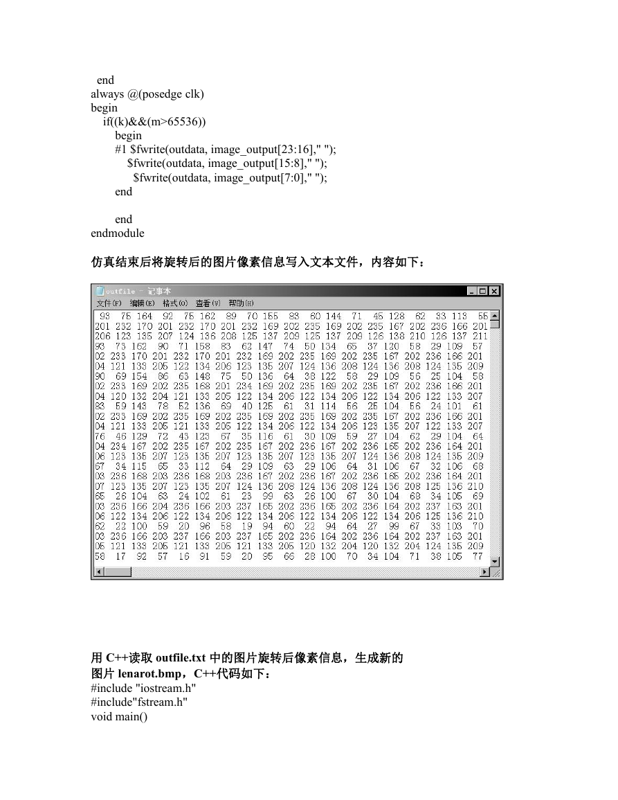
仿真结束后将旋转后的图片像素信息写入文本文件,内容如下:
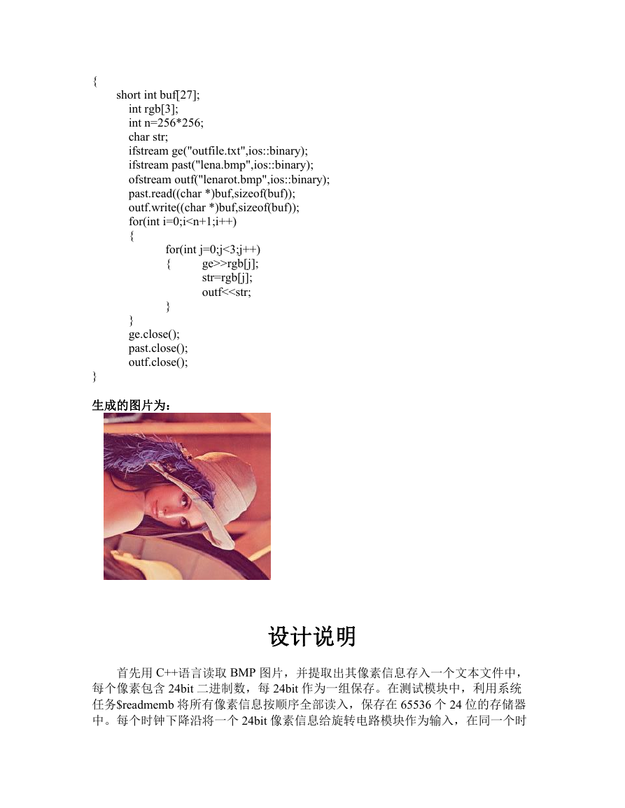
用 C++读取 outfile.txt 中的图片旋转后像素信息,生成新的
图片 lenarot.bmp,C++代码如下:
#include "iostream.h"
#include"fstream.h"
void main()
�
{
}
short int buf[27];
int rgb[3];
int n=256*256;
char str;
ifstream ge("outfile.txt",ios::binary);
ifstream past("lena.bmp",ios::binary);
ofstream outf("lenarot.bmp",ios::binary);
past.read((char *)buf,sizeof(buf));
outf.write((char *)buf,sizeof(buf));
for(int i=0;i
>rgb[j];
{
str=rgb[j];
outf<钟周期里的上升沿计算出该像素经过旋转后的位置,并保存到相应的存储器中。经
过 65536 个时钟周期,所有像素输入完成并且都保存到旋转后的相应位置的存储器
中。然后开始输出,按照 0~65535 的顺序输出存储器中的像素信息,每次输出
24bit 数据,每个时钟下降沿将像素信息写到另一个文本文件中,每 8bit 按十进制
保存,经过 65536 个时钟周期完成输出。最后用 C++读取这个文本文件里的像素
信息和原图片里的位图文件头信息,生成旋转后的图片。
成员工作总结
:我负责编写测试模块。利用系统任务$readmemb 将文本文件中的像素信息
读入存储器中,在和魏政鸿商定后,我利用 65536 个存储器,每个存储器存 24 比
特数据,这样方便将数据作为输入信号传给电路,每个时钟节拍,按原始图片的像
素顺序传给旋转电路模块的输入端一个 24 比特的像素数据,用于其处理。比较重
要和关键的一个问题就是掌握输入和输出的开始时刻,因为旋转电路中输入和输出
不是同步的,所以测试模块中要与之对应。我用 i 和 m 进行计数,i 用于记录输入
的进度,m 用于全程计数,在 m〉65536 后开始输出,这样就较简单地实现了输入
和输出的有序进行。编程过程中遇到的一个问题是确定输出的开始时刻,原来写的
不是 65536,结果发现旋转后的像素文本文件中开头出现了 3 个或 6 个 z , 这说明
输入还没完成时就开始输出,输出了高阻。通过做这个大作业,我对 verilog 更加
熟悉了,在和其他组员讨论中也有很大的收获。
:在编写旋转电路模块时,利用行、列计数器记录每次输入的像素处在第几
行和第几列,这样不仅可以方便地监测数据输入进程,更重要的是方便计算旋转后
该像素处在第几行和第几列,并且可以算出应该保存在第几个存储器中。在设计输
入和输出的时序时,考虑到输入的像素并不是按照 0~65535 的顺序保存到存储器
中的,因此,如果所有像素还没有输入完,即还没有都按旋转后的顺序保存到存储
器中就开始输出的话,一些存储器中还没来得及存储数据,这必然会导致输出不正
确,因此采取的方法是先让数据都输入并保存到相应存储器中,在此过程中令输出
一直为高阻,输入全部完成后再进行输出,输入和输出分别占用 256*256=65536
个时钟周期。在写代码的过程中,我更加体会到了行为建模的优越性,只需考虑电
路的功能,而无需考虑具体的电路结构。让我感触很深的一点是语法结构必须严谨
无误,否则会造成意想不到的结果。开始时,我忘记在最后输出的 else 后的两个
语句前后写上 begin end ,没有将两条语句包含成一个语句块,结果导致输出的图
片左上角缺失。后来与同学讨论并改正后,才输出正确的旋转图片。可见,编写程
序时,必须严格遵守语法。还有一点,原来计算寄存器地址时用 256*row+column,
后来听老师讲了这样会生成复杂的乘法器,我就改用移位运算符。我体会到团队合
作的重要性,团队成员之间互相学习、帮助会大大提高工作效率。
�


 2023年江西萍乡中考道德与法治真题及答案.doc
 2012年重庆南川中考生物真题及答案.doc
 2013年江西师范大学地理学综合及文艺理论基础考研真题.doc
 2020年四川甘孜小升初语文真题及答案I卷.doc
 2020年注册岩土工程师专业基础考试真题及答案.doc
 2023-2024学年福建省厦门市九年级上学期数学月考试题及答案.doc
 2021-2022学年辽宁省沈阳市大东区九年级上学期语文期末试题及答案.doc
 2022-2023学年北京东城区初三第一学期物理期末试卷及答案.doc
 2018上半年江西教师资格初中地理学科知识与教学能力真题及答案.doc
 2012年河北国家公务员申论考试真题及答案-省级.doc
 2020-2021学年江苏省扬州市江都区邵樊片九年级上学期数学第一次质量检测试题及答案.doc
 2022下半年黑龙江教师资格证中学综合素质真题及答案.doc