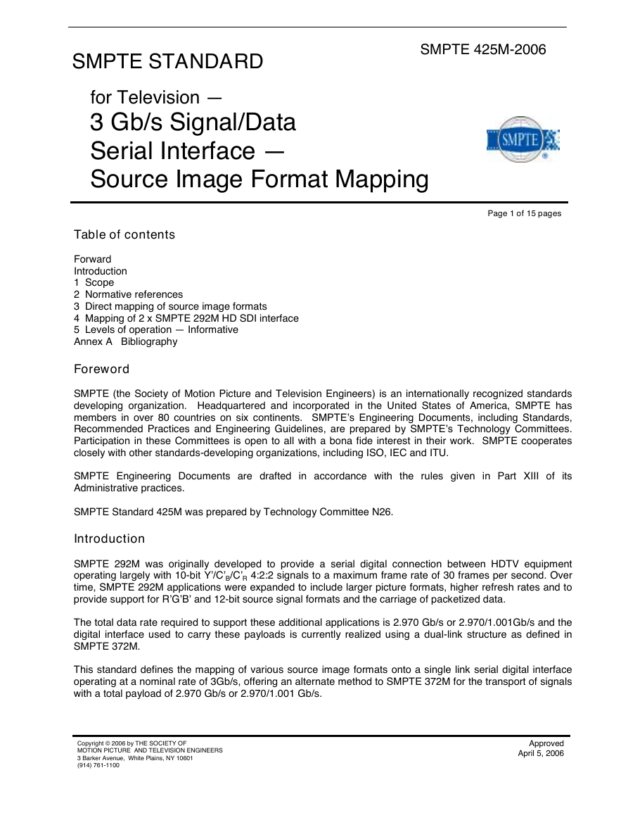
SMPTE 425M-2006
Page 1 of 15 pages
for Television —
3 Gb/s Signal/Data
Serial Interface —
Source Image Format Mapping
SMPTE STANDARD
Table of contents
Forward
Introduction
1 Scope
2 Normative references
3 Direct mapping of source image formats
4 Mapping of 2 x SMPTE 292M HD SDI interface
5 Levels of operation — Informative
Annex A Bibliography
Foreword
SMPTE (the Society of Motion Picture and Television Engineers) is an internationally recognized standards
developing organization. Headquartered and incorporated in the United States of America, SMPTE has
members in over 80 countries on six continents. SMPTE’s Engineering Documents, including Standards,
Recommended Practices and Engineering Guidelines, are prepared by SMPTE’s Technology Committees.
Participation in these Committees is open to all with a bona fide interest in their work. SMPTE cooperates
closely with other standards-developing organizations, including ISO, IEC and ITU.
SMPTE Engineering Documents are drafted in accordance with the rules given in Part XIII of its
Administrative practices.
SMPTE Standard 425M was prepared by Technology Committee N26.
Introduction
SMPTE 292M was originally developed to provide a serial digital connection between HDTV equipment
operating largely with 10-bit Y’/C’B/C’R 4:2:2 signals to a maximum frame rate of 30 frames per second. Over
time, SMPTE 292M applications were expanded to include larger picture formats, higher refresh rates and to
provide support for R’G’B’ and 12-bit source signal formats and the carriage of packetized data.
The total data rate required to support these additional applications is 2.970 Gb/s or 2.970/1.001Gb/s and the
digital interface used to carry these payloads is currently realized using a dual-link structure as defined in
SMPTE 372M.
This standard defines the mapping of various source image formats onto a single link serial digital interface
operating at a nominal rate of 3Gb/s, offering an alternate method to SMPTE 372M for the transport of signals
with a total payload of 2.970 Gb/s or 2.970/1.001 Gb/s.
Copyright © 2006 by THE SOCIETY OF
MOTION PICTURE AND TELEVISION ENGINEERS
3 Barker Avenue, White Plains, NY 10601
(914) 761-1100
Approved
April 5, 2006
�
SMPTE 425M-2006
1 Scope
This standard specifies the direct mapping of various source image formats as defined in table 1; the carriage
of embedded audio; the carriage of ancillary data and the stream ID, in a serial digital interface operating at a
nominal rate of 3Gb/s.
This standard also specifies the mapping of 2 x SMPTE 292M HD SDI interfaces including SMPTE 372M,
Dual Link 292M Interface for 1920 x 1080 Picture Raster, into a serial digital interface operating at a nominal
rate of 3Gb/s.
2 Normative references
The following standards contain provisions, which, through reference in this text, constitute provisions of this
standard. At the time of publication, the editions indicated were valid. All standards are subject to revision,
and parties to agreements based on this standard are encouraged to investigate the possibility of applying the
most recent edition of the standards indicated below.
SMPTE 274M-2005, Television — 1920 x 1080 Image Sample Structure, Digital Representation and Digital
Timing Reference Sequences for Multiple Picture Rates
SMPTE 291M-1998, Television — Ancillary Data Packet and Space Formatting
SMPTE 292M-1998, Television — Bit-Serial Digital Interface For High-Definition Television Systems
SMPTE 296M-2001, Television — 1280 x 720 Progressive Image Sample Structure — Analog and Digital
Representation and Analog Interface
SMPTE 299M-2004, Television — 24-Bit Digital Audio Format for SMPTE 292M Bit-Serial Interface
SMPTE 352M-2002, Television (Dynamic) — Video Payload Identification for Digital Interfaces
SMPTE 372M-2002, Television — Dual Link 292M Interface for 1920 x 1080 Picture Raster.
SMPTE RP 188-1999, Transmission of Time Code and Control Code in the Ancillary Data Space of a Digital
Television Data Stream
3 Direct mapping of source image formats
For this interface, the source data shall be an uncompressed 10-bit or 12-bit video signal corresponding
to the source image formats identified in table 1, or packetized data.
An auxiliary component signal designated A or Alpha, may optionally accompany the R’G’B’ or Y’C’BC’R
video signal. Interfaces containing the auxiliary component are denoted as R’G’B’+A and Y’C’BC’R+A.
The auxiliary component is referred to as either the A channel or Alpha channel in this document. The A
or Alpha channel component if present shall have the same characteristics as the Y’ or G’ channel as
defined in the source image formatting document.
Page 2 of 15 pages
�
Mapping
structure
1
2
3
4
296M
1280 x 720
274M
1920 x 1080
274M
1920 x 1080
4:4:4 (R’G’B’),
4:4:4:4 (R’G’B’ +A)/10-bit
4:4:4 (Y’C’BC’R),
4:4:4:4 (Y’C’BC’R+A)/10-bit
4:4:4 (R’G’B’),
4:4:4:4 (R’G’B’ +A)/10-bit
4:4:4 (Y’C’BC’R),
4:4:4:4 (Y’C’BC’R+A)/10-bit
4:4:4 (R’G’B’)/12-bit
4:4:4 (Y’C’BC’R)/12-bit
274M
1920 x 1080
4:2:2 (Y’C’BC’R)/12-bit
60, 60/1.001 and 50 Frames Progressive
30, 30/1.001, 25, 24 and 24/1.001
Frames Progressive
60, 60/1.001 and 50 Fields Interlaced
30, 30/1.001, 25, 24 and 24/1.001
Frames Progressive
60, 60/1.001 and 50 Fields Interlaced
30, 30/1.001, 25, 24 and 24/1.001
Frames Progressive
30, 30/1.001, 25, 24 and 24/1.001
Frames Progressive
60, 60/1.001 and 50 Fields Interlaced
SMPTE 425M-2006
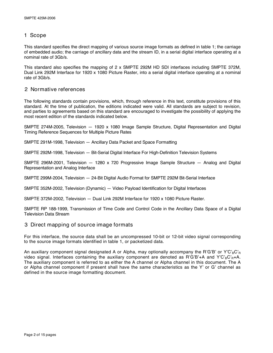
Table 1 –Source image formats
Image format
Signal format sampling
structure/pixel depth
Frame/field rates
1920 × 1080
4:2:2 (Y’C’BC’R)/10-bit
60, 60/1.001 and 50 Frames Progressive
Reference
SMPTE
standard
274M
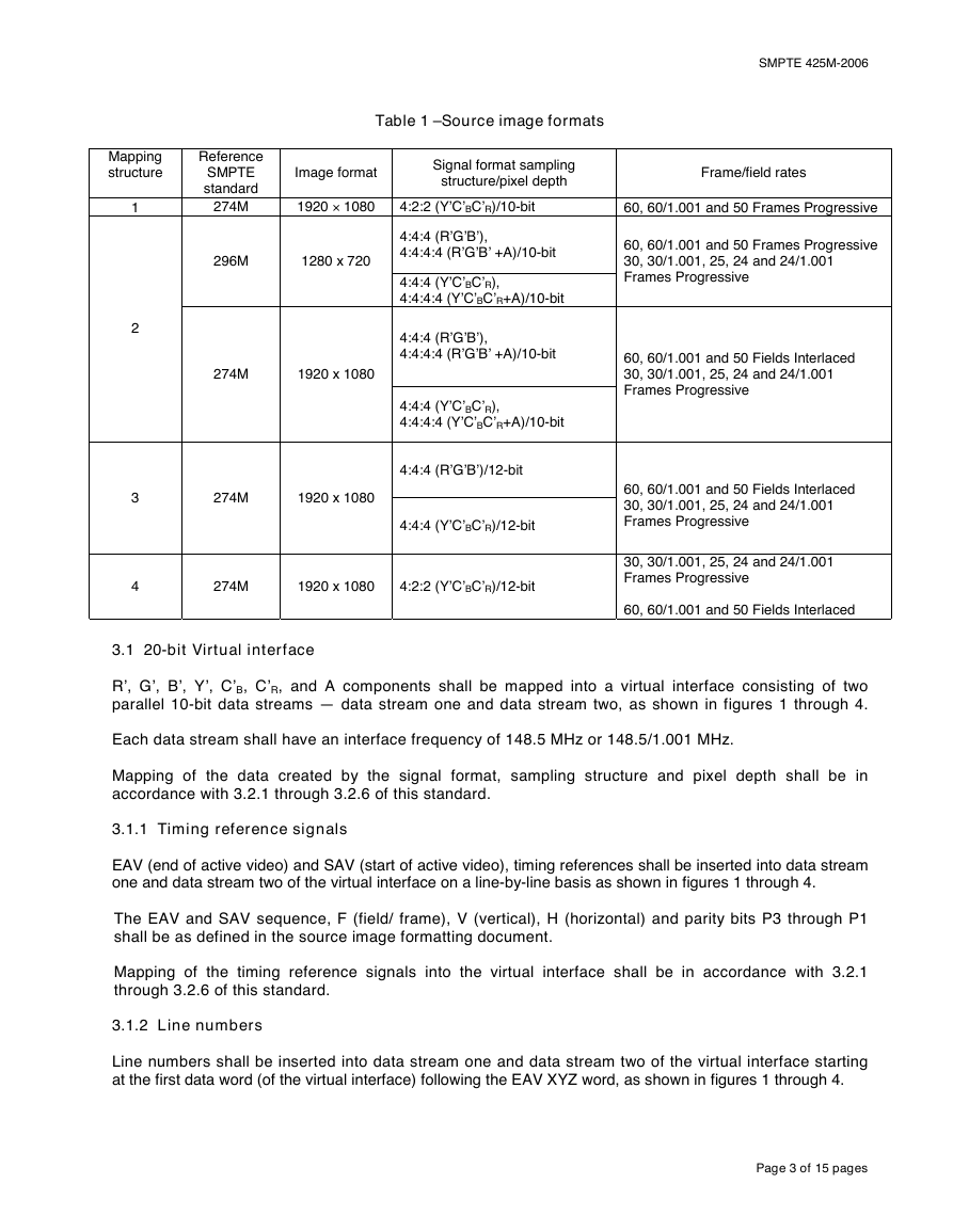
3.1 20-bit Virtual interface
R’, G’, B’, Y’, C’B, C’R, and A components shall be mapped into a virtual interface consisting of two
parallel 10-bit data streams — data stream one and data stream two, as shown in figures 1 through 4.
Each data stream shall have an interface frequency of 148.5 MHz or 148.5/1.001 MHz.
Mapping of the data created by the signal format, sampling structure and pixel depth shall be in
accordance with 3.2.1 through 3.2.6 of this standard.
3.1.1 Timing reference signals
EAV (end of active video) and SAV (start of active video), timing references shall be inserted into data stream
one and data stream two of the virtual interface on a line-by-line basis as shown in figures 1 through 4.
The EAV and SAV sequence, F (field/ frame), V (vertical), H (horizontal) and parity bits P3 through P1
shall be as defined in the source image formatting document.
Mapping of the timing reference signals into the virtual interface shall be in accordance with 3.2.1
through 3.2.6 of this standard.
3.1.2 Line numbers
Line numbers shall be inserted into data stream one and data stream two of the virtual interface starting
at the first data word (of the virtual interface) following the EAV XYZ word, as shown in figures 1 through 4.
Page 3 of 15 pages
�
SMPTE 425M-2006
The virtual interface line numbers shall be in accordance with the picture source line numbers as defined
in the source image formatting document.
Line number data are composed of two words, LN0 and LN1 and shall be as shown in table 2.
Table 2 – Line number data
9 (msb)
LN0
LN1
—
B8
—
B8
8
L6
7
L5
6
L4
5
L3
Res
Res
Res
L10
4
L2
L9
3
L1
L8
2
L0
L7
1
0 (lsb)
Res
Res
Res
Res
NOTES
1 L10 : L0 = line number in binary code.
2 Res = reserved, set to "0" and shall be ignored by receivers.
3.1.3 Line CRC codes
CRC (Cyclic Redundancy Codes) shall be inserted into data stream one and data stream two of the
virtual interface starting at the first data word (of the virtual interface) following the final word of the line
number – LN1, as shown in figures 1 through 4.
The CRC code words are used to detect errors in the active digital line, the EAV timing reference signal
and line number words which follows it. The error detection code consists of two words determined by the
polynomial generator equation:
CRC(X) = X18 + X5 + X4 + 1
The initial value of the CRC is set to zero. The calculation starts at the first active line word of the virtual
interface and ends at the final word of the line number – LN1.
Independent CRC codes shall be produced for data stream one and data stream two of the virtual interface.
The two words of the CRC code shall be as shown in table 3.
Table 3 – CRC data
9 (msb)
8
7
6
5
4
3
2
1
0 (lsb)
CR0
CR1
—
B8
—
B8
CRC8
CRC7
CRC6
CRC5
CRC4
CRC3
CRC2
CRC1
CRC0
CRC17 CRC16 CRC15 CRC14
CRC13
CRC12 CRC11
CRC10 CRC9
NOTE – Users should be aware that data stream one and data stream two of the virtual interface may carry any type
of data as defined by the application.
Page 4 of 15 pages
�
SMPTE 425M-2006
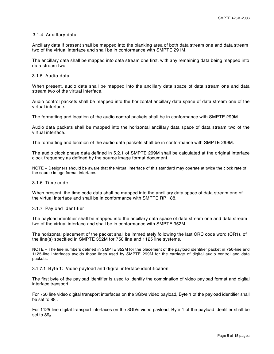
3.1.4 Ancillary data
Ancillary data if present shall be mapped into the blanking area of both data stream one and data stream
two of the virtual interface and shall be in conformance with SMPTE 291M.
The ancillary data shall be mapped into data stream one first, with any remaining data being mapped into
data stream two.
3.1.5 Audio data
When present, audio data shall be mapped into the ancillary data space of data stream one and data
stream two of the virtual interface.
Audio control packets shall be mapped into the horizontal ancillary data space of data stream one of the
virtual interface.
The formatting and location of the audio control packets shall be in conformance with SMPTE 299M.
Audio data packets shall be mapped into the horizontal ancillary data space of data stream two of the
virtual interface.
The formatting and location of the audio data packets shall be in conformance with SMPTE 299M.
The audio clock phase data defined in 5.2.1 of SMPTE 299M shall be calculated at the original interface
clock frequency as defined by the source image format document.
NOTE – Designers should be aware that the virtual interface of this standard may operate at twice the clock rate of
the source image format interface.
3.1.6 Time code
When present, the time code data shall be mapped into the ancillary data space of data stream one of
the virtual interface and shall be in conformance with SMPTE RP 188.
3.1.7 Payload identifier
The payload identifier shall be mapped into the ancillary data space of data stream one and data stream
two of the virtual interface and shall be in conformance with SMPTE 352M.
The horizontal placement of the packet shall be immediately following the last CRC code word (CR1), of
the line(s) specified in SMPTE 352M for 750 line and 1125 line systems.
NOTE – The line numbers defined in SMPTE 352M for the placement of the payload identifier packet in 750-line and
1125-line interfaces avoids those lines used by SMPTE 299M for the carriage of digital audio control and data
packets.
3.1.7.1 Byte 1: Video payload and digital interface identification
The first byte of the payload identifier is used to identify the combination of video payload format and digital
interface transport.
For 750 line video digital transport interfaces on the 3Gb/s video payload, Byte 1 of the payload identifier shall
be set to 88h.
For 1125 line digital transport interfaces on the 3Gb/s video payload, Byte 1 of the payload identifier shall be
set to 89h.
Page 5 of 15 pages
�
SMPTE 425M-2006
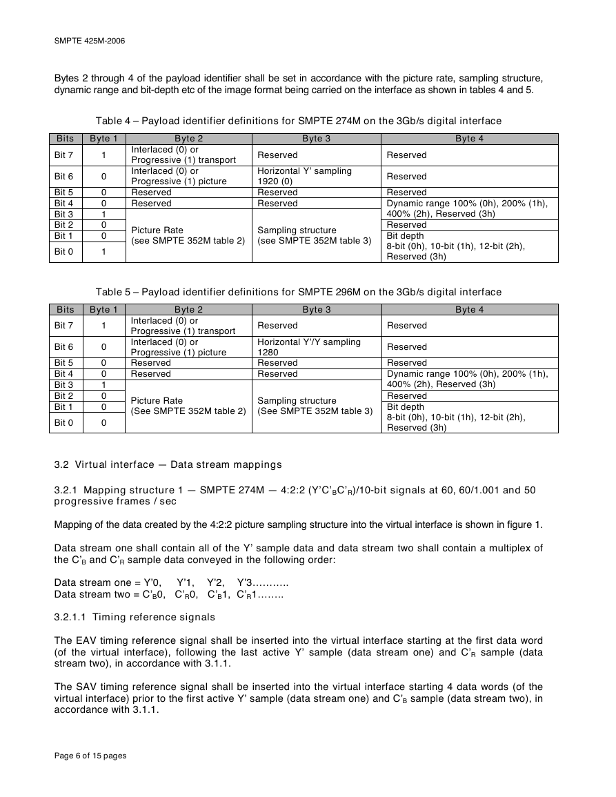
Bytes 2 through 4 of the payload identifier shall be set in accordance with the picture rate, sampling structure,
dynamic range and bit-depth etc of the image format being carried on the interface as shown in tables 4 and 5.
Table 4 – Payload identifier definitions for SMPTE 274M on the 3Gb/s digital interface
Bits Byte 1
Bit 7
1
0
0
0
1
0
0
1
Bit 6
Bit 5
Bit 4
Bit 3
Bit 2
Bit 1
Bit 0
Byte 2
Interlaced (0) or
Progressive (1) transport
Interlaced (0) or
Progressive (1) picture
Reserved
Reserved
Byte 3
Reserved
Horizontal Y’ sampling
1920 (0)
Reserved
Reserved
Picture Rate
(see SMPTE 352M table 2)
Sampling structure
(see SMPTE 352M table 3)
Byte 4
Reserved
Reserved
Reserved
Dynamic range 100% (0h), 200% (1h),
400% (2h), Reserved (3h)
Reserved
Bit depth
8-bit (0h), 10-bit (1h), 12-bit (2h),
Reserved (3h)
Table 5 – Payload identifier definitions for SMPTE 296M on the 3Gb/s digital interface
Bits Byte 1
Bit 7
1
Byte 3
Byte 4
Reserved
Byte 2
Interlaced (0) or
Progressive (1) transport
Interlaced (0) or
Progressive (1) picture
Reserved
Reserved
Picture Rate
(See SMPTE 352M table 2)
Reserved
Horizontal Y’/Y sampling
1280
Reserved
Reserved
0
0
0
1
0
0
0
8-bit (0h), 10-bit (1h), 12-bit (2h),
Reserved (3h)
Reserved
Reserved
Dynamic range 100% (0h), 200% (1h),
400% (2h), Reserved (3h)
Reserved
Sampling structure
(See SMPTE 352M table 3) Bit depth
Bit 6
Bit 5
Bit 4
Bit 3
Bit 2
Bit 1
Bit 0
3.2 Virtual interface — Data stream mappings
3.2.1 Mapping structure 1 — SMPTE 274M — 4:2:2 (Y’C’BC’R)/10-bit signals at 60, 60/1.001 and 50
progressive frames / sec
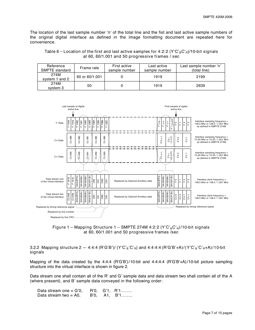
Mapping of the data created by the 4:2:2 picture sampling structure into the virtual interface is shown in figure 1.
Data stream one shall contain all of the Y’ sample data and data stream two shall contain a multiplex of
the C’B and C’R sample data conveyed in the following order:
Data stream one = Y’0, Y’1, Y’2, Y’3………..
Data stream two = C’B0, C’R0, C’B1, C’R1……..
3.2.1.1 Timing reference signals
The EAV timing reference signal shall be inserted into the virtual interface starting at the first data word
(of the virtual interface), following the last active Y’ sample (data stream one) and C’R sample (data
stream two), in accordance with 3.1.1.
The SAV timing reference signal shall be inserted into the virtual interface starting 4 data words (of the
virtual interface) prior to the first active Y’ sample (data stream one) and C’B sample (data stream two), in
accordance with 3.1.1.
Page 6 of 15 pages
�
SMPTE 425M-2006
The location of the last sample number ‘n’ of the total line and the fist and last active sample numbers of
the original digital interface as defined in the image formatting document are repeated here for
convenience.
Table 6 – Location of the first and last active samples for 4:2:2 (Y’C’BC’R)/10-bit signals
at 60, 60/1.001 and 50 progressive frames / sec
Reference
SMPTE standard
274M
system 1 and 2
274M
system 3
Frame rate
60 or 60/1.001
50
First active
sample number
Last active
sample number
Last sample number ‘n’
(total line)
0
0
1919
1919
2199
2639
Last sample of digital
active line
First sample of digital
active line
Y’ Data
8
1
9
1
’
Y
9
1
9
1
’
Y
0
2
9
1
’
Y
1
2
9
1
’
Y
2
2
9
1
’
Y
3
2
9
1
’
Y
4
2
9
1
’
Y
5
2
9
1
’
Y
6
2
9
1
’
Y
7
2
9
1
’
Y
C’B Data
9
5
9
B
C
’
0
6
9
B
C
’
1
6
9
B
C
’
2
6
9
B
C
’
3
6
9
B
C
’
9
5
9
R
C
’
0
6
9
R
C
’
1
6
9
R
C
’
2
6
9
R
C
’
3
6
9
R
C
’
)
3
-
n
(
’
Y
)
2
-
n
(
’
Y
)
1
-
n
(
’
Y
l
e
p
m
a
s
t
s
a
l
n
’
Y
0
’
Y
1
’
Y
2
’
Y
3
’
Y
Interface sampling frequency =
148.5 Mhz or 148.5 / 1.001 Mhz
as defined in SMPTE 274M
)
1
-
n
(
B
C
’
)
1
-
n
(
R
C
’
n
B
C
’
l
e
p
m
a
s
t
s
a
l
n
R
C
’
l
e
p
m
a
s
t
s
a
0
B
C
’
1
B
C
’
Interface sampling frequency =
74.25 Mhz or 74.25 / 1.001 Mhz
as defined in SMPTE 274M
0
R
C
’
1
R
C
’
Interface sampling frequency =
74.25 Mhz or 74.25 / 1.001 Mhz
as defined in SMPTE 274M
C’R Data
Data stream one
of the virtual interface
8
1
9
1
’
Y
9
1
9
1
’
Y
)
h
F
F
3
(
V
A
E
)
h
0
0
0
(
V
A
E
)
h
0
0
0
(
V
A
E
Data stream two
of the virtual interface
9
5
9
B
C
’
9
5
9
R
C
’
)
h
F
F
3
(
V
A
E
)
h
0
0
0
(
V
A
E
)
h
0
0
0
(
V
A
E
Replaced by timing reference signal
Replaced by line number
Replaced by line CRC
)
h
Z
Y
X
V
A
E
(
)
h
Z
Y
X
V
A
E
(
0
N
L
1
N
L
0
R
C
1
R
C
Replaced by Optional Ancillary data
0
N
L
1
N
L
0
R
C
1
R
C
Replaced by Optional Ancillary data
l
)
h
Z
Y
X
V
A
S
(
)
h
Z
Y
X
V
A
S
(
)
h
F
F
3
(
V
A
S
)
h
0
0
0
(
V
A
S
)
h
0
0
0
(
V
A
S
)
h
F
F
3
(
V
A
S
)
h
0
0
0
(
V
A
S
)
h
0
0
0
(
V
A
S
0
’
Y
1
’
Y
2
’
Y
3
’
Y
Interface clock frequency =
148.5 Mhz or 148.5 / 1.001 Mhz
0
’
B
C
’
0
R
C
’
1
’
B
C
’
1
R
C
’
Interface clock frequency =
148.5 Mhz or 148.5 / 1.001 Mhz
Replaced by timing reference signal
Figure 1 – Mapping Structure 1 – SMPTE 274M 4:2:2 (Y’C’BC’R)/10-bit signals
at 60, 60/1.001 and 50 progressive frames /sec
3.2.2 Mapping structure 2 — 4:4:4 (R’G’B’)/ (Y’C’B’C’R) and 4:4:4:4 (R’G’B’+A)/(Y’C’B’C’R+A)/10-bit
signals
Mapping of the data created by the 4:4:4 (R’G’B’)/10-bit and 4:4:4:4 (R’G’B’+A)/10-bit picture sampling
structure into the virtual interface is shown in figure 2.
Data stream one shall contain all of the R’ and G’ sample data and data stream two shall contain all of the A
(where present), and B’ sample data conveyed in the following order:
Data stream one = G’0, R’0, G’1, R’1……..
Data stream two = A0,
B’0, A1, B’1……..
Page 7 of 15 pages
�
SMPTE 425M-2006
Mapping of the data created by the 4:4:4 (Y’C’B’C’R) and 4:4:4:4 (Y’C’B’C’R+A)/10-bit image sampling
structure on to the virtual interface shall be as shown in figure 2 except that:
the R’ samples shall be replaced with C’R samples;
the G’ samples shall be replaced with Y’ samples;
the B’ samples shall be replaced with C’B samples.
3.2.2.1 Timing reference signals
The EAV timing reference signal shall be inserted into the virtual interface starting at the first data word
(of the virtual interface), following the last active G’ sample (data stream one) and R’ sample (data
stream two), in accordance with 3.1.1.
The SAV timing reference signal shall be inserted into the virtual interface starting 4 data words (of the
virtual interface) prior to the first active B’ sample (data stream one) and A sample (data stream two), in
accordance with 3.1.1.
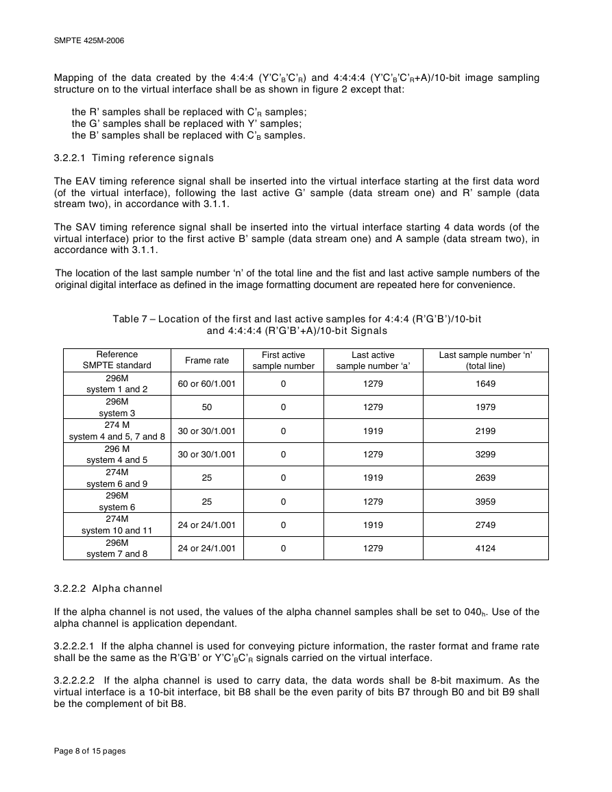
The location of the last sample number ‘n’ of the total line and the fist and last active sample numbers of the
original digital interface as defined in the image formatting document are repeated here for convenience.
Table 7 – Location of the first and last active samples for 4:4:4 (R’G’B’)/10-bit
and 4:4:4:4 (R’G’B’+A)/10-bit Signals
Reference
SMPTE standard
system 4 and 5, 7 and 8
296M
system 1 and 2
296M
system 3
274 M
296 M
system 4 and 5
274M
system 6 and 9
296M
system 6
274M
system 10 and 11
296M
system 7 and 8
Frame rate
60 or 60/1.001
50
30 or 30/1.001
30 or 30/1.001
25
25
24 or 24/1.001
24 or 24/1.001
First active
sample number
Last active
sample number ‘a’
Last sample number ‘n’
(total line)
0
0
0
0
0
0
0
0
1279
1279
1919
1279
1919
1279
1919
1279
1649
1979
2199
3299
2639
3959
2749
4124
3.2.2.2 Alpha channel
If the alpha channel is not used, the values of the alpha channel samples shall be set to 040h. Use of the
alpha channel is application dependant.
3.2.2.2.1 If the alpha channel is used for conveying picture information, the raster format and frame rate
shall be the same as the R’G’B’ or Y’C’BC’R signals carried on the virtual interface.
3.2.2.2.2 If the alpha channel is used to carry data, the data words shall be 8-bit maximum. As the
virtual interface is a 10-bit interface, bit B8 shall be the even parity of bits B7 through B0 and bit B9 shall
be the complement of bit B8.
Page 8 of 15 pages
�



 2023年江西萍乡中考道德与法治真题及答案.doc
 2012年重庆南川中考生物真题及答案.doc
 2013年江西师范大学地理学综合及文艺理论基础考研真题.doc
 2020年四川甘孜小升初语文真题及答案I卷.doc
 2020年注册岩土工程师专业基础考试真题及答案.doc
 2023-2024学年福建省厦门市九年级上学期数学月考试题及答案.doc
 2021-2022学年辽宁省沈阳市大东区九年级上学期语文期末试题及答案.doc
 2022-2023学年北京东城区初三第一学期物理期末试卷及答案.doc
 2018上半年江西教师资格初中地理学科知识与教学能力真题及答案.doc
 2012年河北国家公务员申论考试真题及答案-省级.doc
 2020-2021学年江苏省扬州市江都区邵樊片九年级上学期数学第一次质量检测试题及答案.doc
 2022下半年黑龙江教师资格证中学综合素质真题及答案.doc