IEC 61373
Edition 2.0 2010-05
®
INTERNATIONAL
STANDARD
NORME
INTERNATIONALE
Railway applications – Rolling stock equipment – Shock and vibration tests
Applications ferroviaires – Matériel roulant – Essais de chocs et vibrations
INTERNATIONAL
ELECTROTECHNICAL
COMMISSION
COMMISSION
ELECTROTECHNIQUE
INTERNATIONALE
ICS 45.060
PRICE CODE
CODE PRIX
V
ISBN 978-2-88910-944-9
colourinside--`,,`````,```,,,,,``,,`,,````,`-`-`,,`,,`,`,,`---�
– 2 –
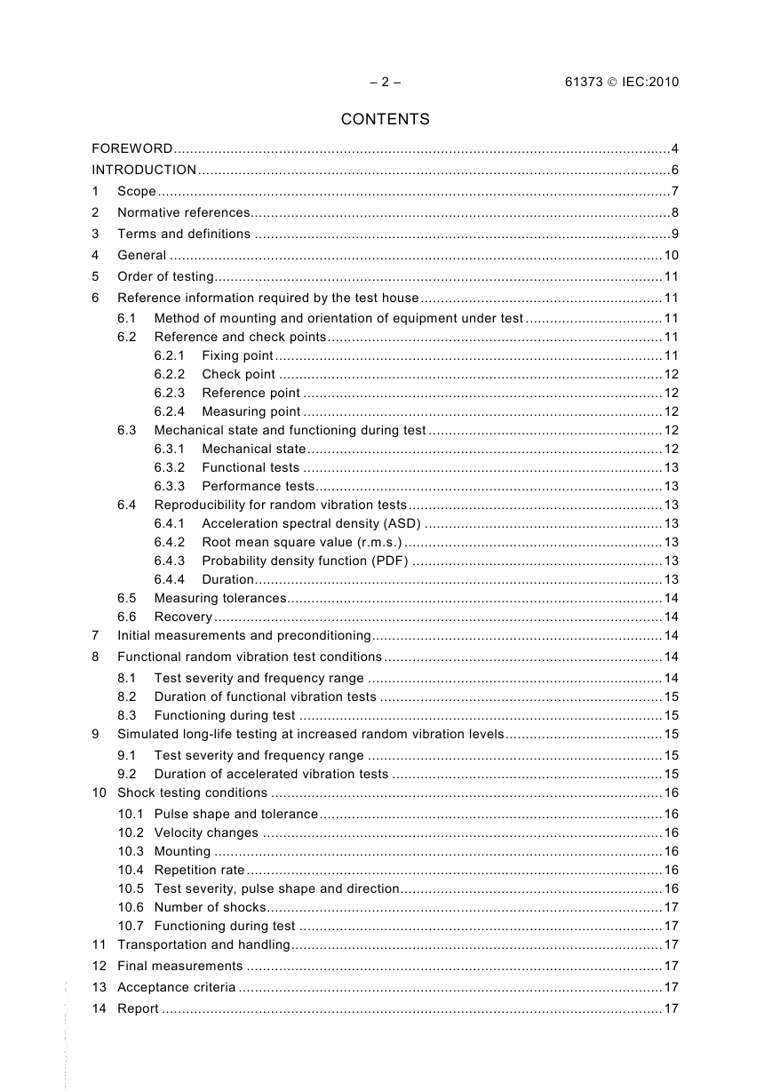
CONTENTS
61373 © IEC:2010
FOREWORD...........................................................................................................................4
INTRODUCTION.....................................................................................................................6
1 Scope...............................................................................................................................7
2 Normative references........................................................................................................8
3 Terms and definitions .......................................................................................................9
4 General ..........................................................................................................................10
5 Order of testing...............................................................................................................11
6 Reference information required by the test house............................................................11
6.1 Method of mounting and orientation of equipment under test ..................................11
6.2 Reference and check points...................................................................................11
6.2.1 Fixing point ................................................................................................11
6.2.2 Check point ...............................................................................................12
6.2.3 Reference point .........................................................................................12
6.2.4 Measuring point .........................................................................................12
6.3 Mechanical state and functioning during test ..........................................................12
6.3.1 Mechanical state........................................................................................12
6.3.2 Functional tests .........................................................................................13
6.3.3 Performance tests......................................................................................13
6.4 Reproducibility for random vibration tests...............................................................13
6.4.1 Acceleration spectral density (ASD) ...........................................................13
6.4.2 Root mean square value (r.m.s.) ................................................................13
6.4.3 Probability density function (PDF) ..............................................................13
6.4.4 Duration.....................................................................................................13
6.5 Measuring tolerances.............................................................................................14
6.6 Recovery ...............................................................................................................14
7
Initial measurements and preconditioning........................................................................14
8 Functional random vibration test conditions .....................................................................14
8.1 Test severity and frequency range .........................................................................14
8.2 Duration of functional vibration tests ......................................................................15
8.3 Functioning during test ..........................................................................................15
9 Simulated long-life testing at increased random vibration levels.......................................15
9.1 Test severity and frequency range .........................................................................15
9.2 Duration of accelerated vibration tests ...................................................................15
10 Shock testing conditions .................................................................................................16
10.1 Pulse shape and tolerance.....................................................................................16
10.2 Velocity changes ...................................................................................................16
10.3 Mounting ...............................................................................................................16
10.4 Repetition rate .......................................................................................................16
10.5 Test severity, pulse shape and direction.................................................................16
10.6 Number of shocks..................................................................................................17
10.7 Functioning during test ..........................................................................................17
11 Transportation and handling............................................................................................17
12 Final measurements .......................................................................................................17
13 Acceptance criteria .........................................................................................................17
14 Report ............................................................................................................................17
--`,,`````,```,,,,,``,,`,,````,`-`-`,,`,,`,`,,`---�
61373 © IEC:2010
– 3 –
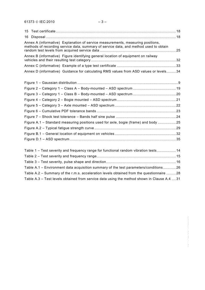
15 Test certificate................................................................................................................18
16 Disposal .........................................................................................................................18
Annex A (informative) Explanation of service measurements, measuring positions,
methods of recording service data, summary of service data, and method used to obtain
random test levels from acquired service data .......................................................................25
Annex B (informative) Figure identifying general location of equipment on railway
vehicles and their resulting test category ...............................................................................32
Annex C (informative) Example of a type test certificate .......................................................33
Annex D (informative) Guidance for calculating RMS values from ASD values or levels.........34
Figure 1 – Gaussian distribution ..............................................................................................9
Figure 2 – Category 1 – Class A – Body-mounted – ASD spectrum ........................................19
Figure 3 – Category 1 – Class B – Body-mounted – ASD spectrum ........................................20
Figure 4 – Category 2 – Bogie mounted – ASD spectrum .......................................................21
Figure 5 – Category 3 – Axle mounted – ASD spectrum .........................................................22
Figure 6 – Cumulative PDF tolerance bands ..........................................................................23
Figure 7 – Shock test tolerance – Bands half sine pulse ........................................................24
Figure A.1 – Standard measuring positions used for axle, bogie (frame) and body .................25
Figure A.2 – Typical fatigue strength curve ............................................................................29
Figure B.1 – General location of equipment on vehicles .........................................................32
Figure D.1 – ASD spectrum ...................................................................................................35
Table 1 – Test severity and frequency range for functional random vibration tests..................14
Table 2 – Test severity and frequency range..........................................................................15
Table 3 – Test severity, pulse shape and direction.................................................................16
Table A.1 – Environment data acquisition summary of the test parameters/conditions ............26
Table A.2 – Summary of the r.m.s. acceleration levels obtained from the questionnaire .........28
Table A.3 – Test levels obtained from service data using the method shown in Clause A.4 ....31
--`,,`````,```,,,,,``,,`,,````,`-`-`,,`,,`,`,,`---�
– 4 –
61373 © IEC:2010
INTERNATIONAL ELECTROTECHNICAL COMMISSION
_____________
RAILWAY APPLICATIONS –
ROLLING STOCK EQUIPMENT –
SHOCK AND VIBRATION TESTS
FOREWORD
1) The International Electrotechnical Commission (IEC) is a worldwide organization for standardization comprising
all national electrotechnical committees (IEC National Committees). The object of IEC is to promote
international co-operation on all questions concerning standardization in the electrical and electronic fields. To
this end and in addition to other activities, IEC publishes International Standards, Technical Specifications,
Technical Reports, Publicly Available Specifications (PAS) and Guides (hereafter referred to as “IEC
Publication(s)”). Their preparation is entrusted to technical committees; any IEC National Committee interested
in the subject dealt with may participate in this preparatory work. International, governmental and non-
governmental organizations liaising with the IEC also participate in this preparation. IEC collaborates closely
with the International Organization for Standardization (ISO) in accordance with conditions determined by
agreement between the two organizations.
2) The formal decisions or agreements of IEC on technical matters express, as nearly as possible, an international
consensus of opinion on the relevant subjects since each technical committee has representation from all
interested IEC National Committees.
3) IEC Publications have the form of recommendations for international use and are accepted by IEC National
Committees in that sense. While all reasonable efforts are made to ensure that the technical content of IEC
Publications is accurate, IEC cannot be held responsible for the way in which they are used or for any
misinterpretation by any end user.
4) In order to promote international uniformity, IEC National Committees undertake to apply IEC Publications
transparently to the maximum extent possible in their national and regional publications. Any divergence
between any IEC Publication and the corresponding national or regional publication shall be clearly indicated in
the latter.
5) IEC itself does not provide any attestation of conformity. Independent certification bodies provide conformity
assessment services and, in some areas, access to IEC marks of conformity. IEC is not responsible for any
services carried out by independent certification bodies.
6) All users should ensure that they have the latest edition of this publication.
7) No liability shall attach to IEC or its directors, employees, servants or agents including individual experts and
members of its technical committees and IEC National Committees for any personal injury, property damage or
other damage of any nature whatsoever, whether direct or indirect, or for costs (including legal fees) and
expenses arising out of the publication, use of, or reliance upon, this IEC Publication or any other IEC
Publications.
8) Attention is drawn to the Normative references cited in this publication. Use of the referenced publications is
indispensable for the correct application of this publication.
9) Attention is drawn to the possibility that some of the elements of this IEC Publication may be the subject of
patent rights. IEC shall not be held responsible for identifying any or all such patent rights.
International Standard IEC 61373 has been prepared by IEC technical committee 9: Electrical
equipment and systems for railways.
This second edition cancels and replaces the first edition, issued in 1999 and constitutes a
technical revision.
The main technical changes with regard to the previous edition are as follows:
– change of the method to calculate the acceleration ratio which has to be applied to the
functional ASD value to obtain the simulated long-life ASD value;
– addition of the notion of partially certified against this standard;
– suppression of Annex B of the first edition due to the new method to calculate the
acceleration ratio;
– addition of guidance for calculating the functional RMS value from service data or the
RMS value from ASD levels of Figures 2 to 5.
--`,,`````,```,,,,,``,,`,,````,`-`-`,,`,,`,`,,`---�
61373 © IEC:2010
– 5 –
The text of this standard is based on the following documents:
FDIS
9/1386/FDIS
Report on voting
9/1397/RVD
Full information on the voting for the approval of this standard can be found in the report on
voting indicated in the above table.
The committee has decided that the contents of this publication will remain unchanged until the
stability date indicated on the IEC web site under "http://webstore.iec.ch" in the data related to
the specific publication. At this date, the publication will be
reconfirmed,
•
• withdrawn,
•
• amended.
replaced by a revised edition, or
IMPORTANT – The 'colour inside' logo on the cover page of this publication indicates
that it contains colours which are considered to be useful for the correct understanding
of its contents. Users should therefore print this document using a colour printer.
--`,,`````,```,,,,,``,,`,,````,`-`-`,,`,,`,`,,`---�
– 6 –
61373 © IEC:2010
INTRODUCTION
This standard covers the requirements for random vibration and shock testing items of
pneumatic, electrical and electronic equipment/components (hereinafter only referred to as
equipment) to be fitted on to railway vehicles. Random vibration is the only method to be used
for equipment/component approval.
The tests contained within this standard are specifically aimed at demonstrating the ability of
the equipment under test to withstand the type of environmental vibration conditions normally
expected for railway vehicles. In order to achieve the best representation possible, the values
quoted in this standard have been derived from actual service measurements submitted by
various bodies from around the world.
This standard is not intended to cover self-induced vibrations as these will be specific to
particular applications.
Engineering judgement and experience is required in the execution and interpretation of this
standard.
This standard is suitable for design and validation purposes; however, it does not exclude the
use of other development tools (such as sine sweep), which may be used to ensure a
predetermined degree of mechanical and operational confidence. The test levels to be applied
to the equipment under test are dictated only by its location on the train (i.e. axle, bogie or
body-mounted).
It should be noted that these tests may be performed on prototypes in order to gain design
information about the product performance under random vibration. However, for test
certification purposes the tests have to be carried out on equipment taken from normal
production.
--`,,`````,```,,,,,``,,`,,````,`-`-`,,`,,`,`,,`---�
61373 © IEC:2010
– 7 –
RAILWAY APPLICATIONS –
ROLLING STOCK EQUIPMENT –
SHOCK AND VIBRATION TESTS
1 Scope
This International Standard specifies the requirements for testing items of equipment intended
for use on railway vehicles which are subsequently subjected to vibrations and shock owing to
the nature of railway operational environment. To gain assurance that the quality of the
equipment is acceptable, it has to withstand tests of reasonable duration that simulate the
service conditions seen throughout its expected life.
Simulated long-life testing can be achieved in a number of ways each having their associated
advantages and disadvantages, the following being the most common:
a) amplification: where the amplitudes are increased and the time base decreased;
b) time compression: where the amplitude history is retained and the time base is decreased
(increase of the frequency);
c) decimation: where time slices of the historical data are removed when the amplitudes are
below a specified threshold value.
The amplification method as stated in a) above, is used in this standard and together with the
publications referred to in Clause 2; it defines the default test procedure to be followed when
vibration testing items for use on railway vehicles. However, other standards exist and may be
used with prior agreement between the manufacturer and the customer. In such cases test
certification against this standard will not apply. Where service information is available tests
can be performed using the method outlined in Annex A. If the levels are lower than those
quoted in this standard, equipment is partially certified against this standard (only for service
conditions giving functional test values lower than or equal to those specified in the test report).
Whilst this standard is primarily concerned with railway vehicles on fixed rail systems, its wider
use is not precluded. For systems operating on pneumatic tyres, or other transportation
systems such as trolleybuses, where the level of shock and vibration clearly differ from those
obtained on fixed rail systems, the supplier and customer can agree on the test levels at the
tender stage. It is recommended that the frequency spectra and the shock duration/amplitude
be determined using the guidelines in Annex A. Equipment tested at levels lower than those
quoted in this standard cannot be fully certified against the requirements of this standard.
An example of this is trolleybuses, whereby body-mounted trolleybus equipment could be
tested in accordance with category 1 equipment referred to in the standard.
This standard applies to single axis testing. However multi-axis testing may be used with prior
agreement between the manufacturer and the customer.
The test values quoted in this standard have been divided into three categories dependent only
upon the equipment’s location within the vehicle.
Category 1 Body mounted
Class A
Cubicles, subassemblies, equipment and components mounted directly on or
under the car body.
--`,,`````,```,,,,,``,,`,,````,`-`-`,,`,,`,`,,`---�
– 8 –
61373 © IEC:2010
Class B
Anything mounted inside an equipment case which is in turn mounted directly on
or under the car body.
NOTE 1 Class B should be used when it is not clear where the equipment is to be located.
Category 2 Bogie mounted
Cubicles, subassemblies, equipment and components which are to be mounted on the bogie of
a railway vehicle.
Category 3 Axle mounted
Subassemblies, equipment and components or assemblies which are to be mounted on the
wheelset assembly of a railway vehicle.
NOTE 2
In the case of equipment mounted on vehicles with one level of suspension such as wagons and trucks,
unless otherwise agreed at the tender stage, axle mounted equipment will be tested as category 3, and all other
equipment will be tested as category 2.
The cost of testing is influenced by the weight, shape and complexity of the equipment under
test. Consequently at the tender stage the supplier may propose a more cost-effective method
of demonstrating compliance with the requirements of this standard. Where alternative
methods are agreed it will be the responsibility of the supplier to demonstrate to his customer
or his representative that the objective of this standard has been met. If an alternative method
of evaluation is agreed, then the equipment tested cannot be certified against the requirement
of this standard.
This standard is intended to evaluate equipment which is attached to the main structure of the
vehicle (and/or components mounted thereon). It is not intended to test equipment which forms
part of the main structure. Main structure in the sense of this standard means car body, bogie
and axle. There are a number of cases where additional or special vibration tests may be
requested by the customer, for example:
a) equipment mounted on, or linked to, items which are known to produce fixed frequency
excitation;
b) equipment such as traction motors, pantographs, shoegear, or suspension components
which may be subjected to tests in accordance with their special requirements, applicable
to their use on railway vehicles. In all such cases the tests carried out should be dealt with
by separate agreement at the tender stage;
c) equipment intended for use in special operational environments as specified by the
customer.
2 Normative references
The following referenced documents are indispensable for the application of this document. For
dated references, only the edition cited applies. For undated references, the latest edition of
the referenced document (including any amendments) applies.
IEC 60068-2-27:2008, Environmental testing – Part 2-27: Tests – Test Ea and guidance: Shock
IEC 60068-2-47:2005, Environmental testing – Part 2-47: Tests – Mounting of specimens for
vibration, impact and similar dynamic tests
IEC 60068-2-64:2008, Environmental
broadband random and guidance
testing – Part 2-64: Tests – Test Fh: Vibration,
ISO 3534-1:2006, Statistics – Vocabulary and symbols – Part 1: Probability and general
statistical terms
--`,,`````,```,,,,,``,,`,,````,`-`-`,,`,,`,`,,`---�



 2023年江西萍乡中考道德与法治真题及答案.doc
 2012年重庆南川中考生物真题及答案.doc
 2013年江西师范大学地理学综合及文艺理论基础考研真题.doc
 2020年四川甘孜小升初语文真题及答案I卷.doc
 2020年注册岩土工程师专业基础考试真题及答案.doc
 2023-2024学年福建省厦门市九年级上学期数学月考试题及答案.doc
 2021-2022学年辽宁省沈阳市大东区九年级上学期语文期末试题及答案.doc
 2022-2023学年北京东城区初三第一学期物理期末试卷及答案.doc
 2018上半年江西教师资格初中地理学科知识与教学能力真题及答案.doc
 2012年河北国家公务员申论考试真题及答案-省级.doc
 2020-2021学年江苏省扬州市江都区邵樊片九年级上学期数学第一次质量检测试题及答案.doc
 2022下半年黑龙江教师资格证中学综合素质真题及答案.doc