Technical Product Information
Y 258 E00 015e
Seite/Page 1 von/of 13
Datum/Date 14.6.2005
Produkt / Product:
Typ / Type:
Bemerkung / Comment:
Nr.
Index
1
Seite
Page
-
Änderung
Revision
Erstausgabe / First Edition
translation to English
Planar Wide Band Lambda Sensor
LSU4.9
All data given in this document are nominal values
and might be subject of change at all time.
Datum
Date
14.6.05
26.8.05
GS-EX/ENG6-
Ham
gez Hamann
GS-EX/ENG6 GS-EX/ENG
gez Meier
gez.
Stanglmeier
1.
2.
3.
4.
5.
Contents
Characteristics
Application conditions
Functional values
Installation instructions
General operating instructions
2
5
7
9
12
©Alle Rechte bei Robert Bosch GmbH, auch für den Fall von Schutzrechtsanmeldungen. Jede Verfügungsbefugnis, wie Kopier- und Weitergaberecht, bei uns.
©Robert Bosch GmbH reserves all rights even in the event of industrial property.We reserve all rights of disposal such as copying and passing on to third parties
�
Technical Product Information
Y 258 E00 015e
Seite/Page 2 von/of 13
Datum/Date 14.6.2005
1.
1.1
1.2
General
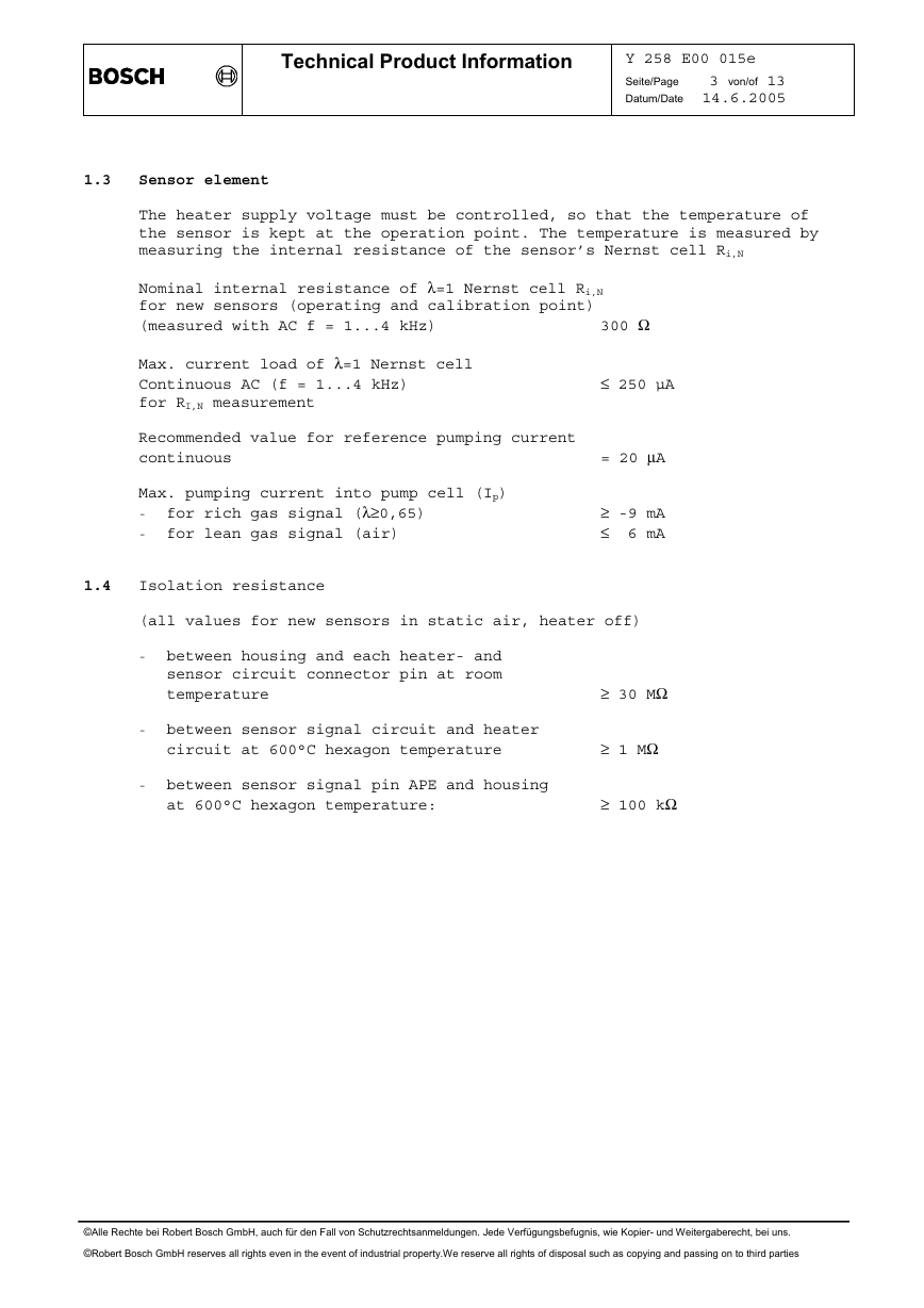
The wide band lambda sensor LSU is a planar ZrO2 dual cell limiting current
sensor with an integrated heater. It is used to measure the oxygen content
and the λ-value of exhaust gases in automotive engines (gasoline and die-
sel). Its monotonic output signal in the range of λ=0.65 to air makes the
LSU capable of being used as an universal sensor for λ=1 measurement as
well as for other λ ranges.
The connector module contains a trimming resistor, which defines the
characteristics of the sensor and is necessary for the sensor function.
The wide band sensor LSU operates only in combination with a special
LSU control unit (e.g. AWS control box, LA4 or CJ125 IC).
Characteristics
Circuit of LSU and control unit
APE
← Ip
red
Trimming Resistor
30-300 Ohm
green
AWS
← Ipmeas
Measuring
Resistance 61.9 Ohm
IP
IA
+
−
IPN
yellow
VM=2,5V
RE
UN
+
−
Reference
Voltage
450 mV
VCC
RV
Sensor Cell
O2, CO, HC, H2
O2−
O2−
H-
H+
20 µA Reference Pump Current
Ri-control
−
+
black
white
grey
red
yellow
white
grey
green
black
Electrical connection:
Pin1: Pumping Current APE
Pin2: Virtual Ground IPN
Pin3: Heater Minus H-
Pin4: Heater Vbatt H+
Pin5: Trim Current RT
Pin6: Nernst Voltage RE+
©Alle Rechte bei Robert Bosch GmbH, auch für den Fall von Schutzrechtsanmeldungen. Jede Verfügungsbefugnis, wie Kopier- und Weitergaberecht, bei uns.
©Robert Bosch GmbH reserves all rights even in the event of industrial property.We reserve all rights of disposal such as copying and passing on to third parties
�
Technical Product Information
Y 258 E00 015e
Seite/Page 3 von/of 13
Datum/Date 14.6.2005
Sensor element
The heater supply voltage must be controlled, so that the temperature of
the sensor is kept at the operation point. The temperature is measured by
measuring the internal resistance of the sensor’s Nernst cell Ri,N
Nominal internal resistance of λ=1 Nernst cell Ri,N
for new sensors (operating and calibration point)
(measured with AC f = 1...4 kHz)
300 Ω
Max. current load of λ=1 Nernst cell
Continuous AC (f = 1...4 kHz)
for RI,N measurement
≤ 250 µA
Recommended value for reference pumping current
continuous
= 20 µA
Max. pumping current into pump cell (Ip)
- for rich gas signal (λ≥0,65)
- for lean gas signal (air)
≥ -9 mA
≤ 6 mA
Isolation resistance
(all values for new sensors in static air, heater off)
- between housing and each heater- and
sensor circuit connector pin at room
temperature
- between sensor signal circuit and heater
circuit at 600°C hexagon temperature
- between sensor signal pin APE and housing
at 600°C hexagon temperature:
≥ 30 MΩ
≥ 1 MΩ
≥ 100 kΩ
1.3
1.4
©Alle Rechte bei Robert Bosch GmbH, auch für den Fall von Schutzrechtsanmeldungen. Jede Verfügungsbefugnis, wie Kopier- und Weitergaberecht, bei uns.
©Robert Bosch GmbH reserves all rights even in the event of industrial property.We reserve all rights of disposal such as copying and passing on to third parties
�
Technical Product Information
Y 258 E00 015e
Seite/Page 4 von/of 13
Datum/Date 14.6.2005
Heater supply
Nominal voltage:
7.5 V
Nominal heater power at 7.5 V heater supply
at thermal equilibrium in air:
approx. 7.5 W
Nominal heater cold resistance at room temp.
for new sensor, including cable and connector
Minimum heater cold resistance at -40°C:
3.2 Ω
1.8 Ω
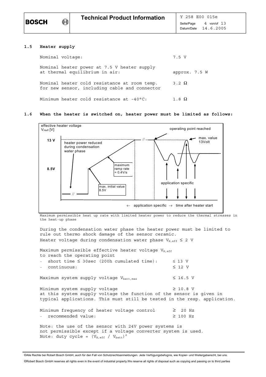
When the heater is switched on, heater power must be limited as follows:
1.5
1.6
effective heater voltage
VHeff [V]
operating point reached
//
max. value
13Volt
13 V
8.5V
heater power reduced
during condensation
water phase
maximum
ramp rate
= 0.4V/s
max. initial value
8.5V
//
application specific
← application specific → time after heater start
Maximum permissible heat up rate with limited heater power to reduce the thermal stresses in
the heat-up phase
During the condensation water phase the heater power must be limited to
rule out thermo shock damage of the sensor ceramic.
Heater voltage during condensation water phase VH,eff ≤ 2 V
Maximum permissible effective heater voltage VH,eff
to reach the operating point
- short time ≤ 30sec (200h cumulated time):
- continuous:
≤ 13 V
≤ 12 V
Maximum system supply voltage Vbatt,max
≤ 16.5 V
Minimum system supply voltage
at this system supply voltage the function of the sensor is given in
typical applications. This must still be tested in the resp. application.
≥ 10.8 V
Minimum frequency of heater voltage control
- recommended value:
≥ 20 Hz
≥ 100 Hz
Note: the use of the sensor with 24V power systems is
not permissible except if a voltage converter system is used.
Note: duty cycle = (VH,eff / Vbatt)2
©Alle Rechte bei Robert Bosch GmbH, auch für den Fall von Schutzrechtsanmeldungen. Jede Verfügungsbefugnis, wie Kopier- und Weitergaberecht, bei uns.
©Robert Bosch GmbH reserves all rights even in the event of industrial property.We reserve all rights of disposal such as copying and passing on to third parties
�
Technical Product Information
Y 258 E00 015e
Seite/Page 5 von/of 13
Datum/Date 14.6.2005
Application conditions
Temperature measurements
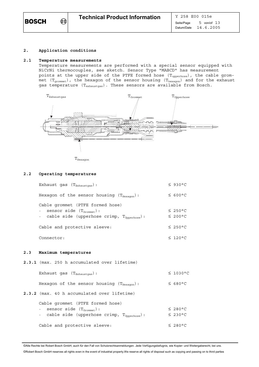
Temperature measurements are performed with a special sensor equipped with
NiCrNi thermocouples, see sketch. Sensor Type "MABCD" has measurement
points at the upper side of the PTFE formed hose (Tupperhose), the cable grom-
met (Tgrommet), the hexagon of the sensor housing (Thexagon) and for the exhaust
gas temperature (Texhaustgas). These sensors are available from Bosch.
TExhaustgas
TGrommet
TUpperhose
2.
2.1
2.2
THexagon
Operating temperatures
Exhaust gas (TExhaustgas):
Hexagon of the sensor housing (THexagon):
Cable grommet (PTFE formed hose)
- sensor side (TGrommet):
- cable side (upperhose crimp, TUpperhose):
≤ 930°C
≤ 600°C
≤ 250°C
≤ 200°C
≤ 250°C
≤ 120°C
≤ 1030°C
≤ 680°C
≤ 280°C
≤ 230°C
≤ 280°C
Cable and protective sleeve:
2.3
2.3.1 (max. 250 h accumulated over lifetime)
Connector:
Maximum temperatures
Exhaust gas (TExhaustgas):
2.3.2 (max. 40 h accumulated over lifetime)
Hexagon of the sensor housing (THexagon):
Cable grommet (PTFE formed hose)
- sensor side (TGrommet):
- cable side (upperhose crimp, TUpperhose):
Cable and protective sleeve:
©Alle Rechte bei Robert Bosch GmbH, auch für den Fall von Schutzrechtsanmeldungen. Jede Verfügungsbefugnis, wie Kopier- und Weitergaberecht, bei uns.
©Robert Bosch GmbH reserves all rights even in the event of industrial property.We reserve all rights of disposal such as copying and passing on to third parties
�
Technical Product Information
Y 258 E00 015e
Seite/Page 6 von/of 13
Datum/Date 14.6.2005
2.4
2.5
2.6
2.7
Exhaust gas pressure (absolute pressure)
- continuous:
- short time, max. 250h cumulated over lifetime ≤ 4 bar
≤ 2.5 bar
Notes:
If the operating temperature ( 2.2) or the max. continuous exhaust gas
pressure ( 2.4) is exceeded, the sensor accuracy might be limited during
this time.
Permissible vibrations
Stochastic vibrations: (peak level)
Sinusoidal vibrations:
≤ 1000 m/s2
≤ 300 m/s2
Corrosion, humidity
The lambda sensor has been developed and tested for use in automotive vehi-
cles, e.g.
- damp heat cycling acc. to IEC 68-2-30 test Db (21 days, 40°C)
- salt mist test acc. to IEC 68-2-11 test Ka, test time 288 h
- temperature cycling test acc. to IEC 68-2-14 test Na,
250 cycles -40°C / 130°C
- sulfur dioxide test with general condensation of moisture acc. to DIN EN
ISO 6988, 6 cycles of 24h
- submergence test IPx7 acc. to IEC 529
Permissible fuel additives
In accordance with DIN EN228 for commercially available unleaded fuel or
EN590 for diesel fuel.
Contamination by other fuels, additives or oil consumption must be deter-
mined by the customer by the way of adequate large-scale tests.
©Alle Rechte bei Robert Bosch GmbH, auch für den Fall von Schutzrechtsanmeldungen. Jede Verfügungsbefugnis, wie Kopier- und Weitergaberecht, bei uns.
©Robert Bosch GmbH reserves all rights even in the event of industrial property.We reserve all rights of disposal such as copying and passing on to third parties
�
Technical Product Information
Y 258 E00 015e
Seite/Page 7 von/of 13
Datum/Date 14.6.2005
3.
3.1
Functional values
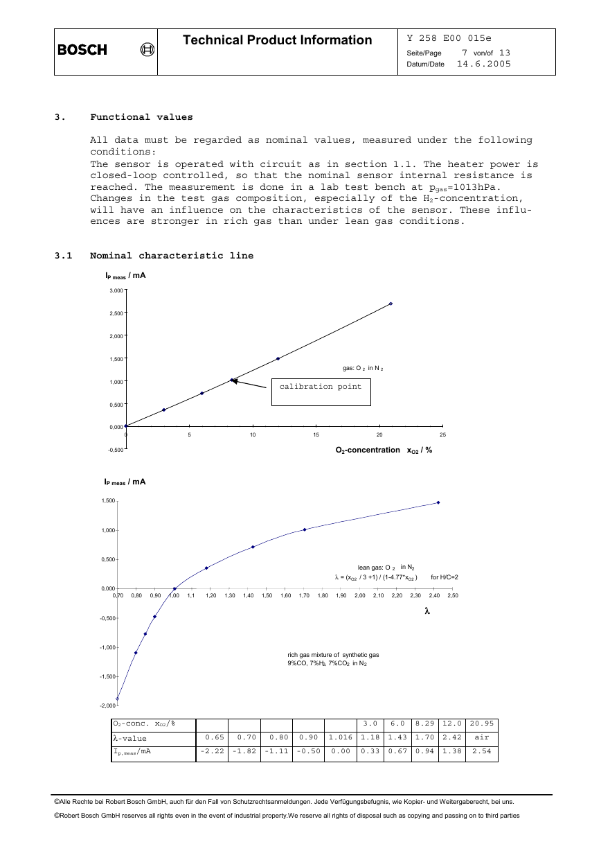
All data must be regarded as nominal values, measured under the following
conditions:
The sensor is operated with circuit as in section 1.1. The heater power is
closed-loop controlled, so that the nominal sensor internal resistance is
reached. The measurement is done in a lab test bench at pgas=1013hPa.
Changes in the test gas composition, especially of the H2-concentration,
will have an influence on the characteristics of the sensor. These influ-
ences are stronger in rich gas than under lean gas conditions.
Nominal characteristic line
IP meas / mA
3,000
2,500
2,000
1,500
1,000
0,500
0,000
0
-0,500
IP meas / mA
gas: O 2 in N 2
calibration point
5
10
15
20
25
O2-concentration xO2 / %
1,500
1,000
0,500
0,000
0,70
-0,500
-1,000
-1,500
-2,000
0,80
0,90
1,00
1,1
1,20
1,30
1,40
1,50
1,60
1,70
1,80
1,90
2,00
2,10
2,20
2,30
2,50
2,40
λ
lean gas: O 2 in N2
λ = (xO2 / 3 +1) / (1-4.77*xO2 ) for H/C=2
rich gas mixture of synthetic gas
9%CO, 7%H2, 7%CO2 in N2
O2-conc. xO2/%
λ-value
Ip,meas/mA
3.0 6.0 8.29 12.0 20.95
0.65 0.70 0.80
0.90 1.016 1.18 1.43 1.70 2.42 air
-2.22 -1.82 -1.11 -0.50
0.00 0.33 0.67 0.94 1.38 2.54
©Alle Rechte bei Robert Bosch GmbH, auch für den Fall von Schutzrechtsanmeldungen. Jede Verfügungsbefugnis, wie Kopier- und Weitergaberecht, bei uns.
©Robert Bosch GmbH reserves all rights even in the event of industrial property.We reserve all rights of disposal such as copying and passing on to third parties
�
Technical Product Information
Y 258 E00 015e
Seite/Page 8 von/of 13
Datum/Date 14.6.2005
3.2
3.3
Time to activity (light-off time)
Guide value for the time to activity after switching
on the sensor heater (“light-off time”)
≤ 10 s
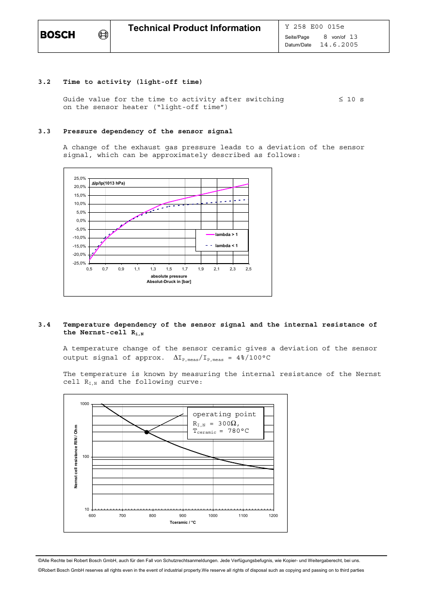
Pressure dependency of the sensor signal
A change of the exhaust gas pressure leads to a deviation of the sensor
signal, which can be approximately described as follows:
∆Ip/Ip(1013 hPa)
25,0%
20,0%
15,0%
10,0%
5,0%
0,0%
-5,0%
-10,0%
-15,0%
-20,0%
-25,0%
0,5
0,7
0,9
1,1
lambda > 1
lambda < 1
1,9
2,1
2,3
2,5
1,5
1,7
1,3
absolute pressure
Absolut-Druck in [bar]
Temperature dependency of the sensor signal and the internal resistance of
the Nernst-cell Ri,N
A temperature change of the sensor ceramic gives a deviation of the sensor
output signal of approx. ∆IP,meas/IP,meas = 4%/100°C
The temperature is known by measuring the internal resistance of the Nernst
cell RI,N and the following curve:
1000
100
operating point
RI,N = 300Ω,
Tceramic = 780°C
m
h
O
/
I
N
R
e
c
n
a
t
s
i
s
e
r
l
l
e
c
t
s
n
r
e
N
10
600
700
800
900
1000
1100
1200
Tceramic / °C
3.4
©Alle Rechte bei Robert Bosch GmbH, auch für den Fall von Schutzrechtsanmeldungen. Jede Verfügungsbefugnis, wie Kopier- und Weitergaberecht, bei uns.
©Robert Bosch GmbH reserves all rights even in the event of industrial property.We reserve all rights of disposal such as copying and passing on to third parties
�




 2023年江西萍乡中考道德与法治真题及答案.doc
 2012年重庆南川中考生物真题及答案.doc
 2013年江西师范大学地理学综合及文艺理论基础考研真题.doc
 2020年四川甘孜小升初语文真题及答案I卷.doc
 2020年注册岩土工程师专业基础考试真题及答案.doc
 2023-2024学年福建省厦门市九年级上学期数学月考试题及答案.doc
 2021-2022学年辽宁省沈阳市大东区九年级上学期语文期末试题及答案.doc
 2022-2023学年北京东城区初三第一学期物理期末试卷及答案.doc
 2018上半年江西教师资格初中地理学科知识与教学能力真题及答案.doc
 2012年河北国家公务员申论考试真题及答案-省级.doc
 2020-2021学年江苏省扬州市江都区邵樊片九年级上学期数学第一次质量检测试题及答案.doc
 2022下半年黑龙江教师资格证中学综合素质真题及答案.doc