logo资料库

IEC61851-23_2014-03.pdf

第1页 / 共78页
第2页 / 共78页
第3页 / 共78页
第4页 / 共78页
第5页 / 共78页
第6页 / 共78页
第7页 / 共78页
第8页 / 共78页
资料共78页,剩余部分请下载后查看
English
CONTENTS
FOREWORD
INTRODUCTION
1 Scope
2 Normative references
3 Terms and definitions
4 General requirements
5 Rating of the supply a.c. voltage
6 General system requirement and interface
7 Protection against electric shock
8 Connection between the power supply and the EV
10 Charging cable assembly requirements
11 EVSE requirements
101 Specific requirements for d.c. EV charging station
102 Communication between EV and d.c. EV charging station
Annex AA (normative) DC EV charging station of system A
Annex BB (normative) DC EV charging station of system B
Annex CC (normative) DC EV charging station of system C(Combined charging system)
Annex DD (informative) Typical d.c. charging systems
Annex EE (informative) Typical configuration of d.c. charging system
Bibliography
Figures
Figure 101 - Overvoltage protection in case of earth fault
Figure 102 - Measuring network of touch current weighted for perception or reaction
Figure 103 - Step response for constant value control
Figure 104 - Current ripple measurement equipment with capacitor
Figure 105 – Maximum ratings for voltage dynamics
Figure AA.1 - Overall schematic of system A station and EV
Figure AA.2 - Interface circuit for charging control of system A station
Figure AA.3 - Failure detection principle by detection of d.c. leakage current
Figure AA.4 - Example of vehicle connector latch and lock monitoring circuit
Figure AA.5 - State transition diagram of charging process for system A
Figure AA.6 - Sequence diagram of system A
Figure AA.7 - Charging current value requested by the vehicle
Figure AA.8 - Output response performance of d.c. EV charging station
Figure BB.1 - Schematic diagram for basic solution for d.c. charging system
Figure BB.2 - Sequence diagram of charging process
Figure BB.3 - Operation flow chart of start charging
Figure BB.4 - Operation flow chart of stop charging
Figure CC.1 - Sequence diagram for normal start up
Figure CC.2 - Sequence diagram and description for normal shutdown
Figure CC.3 – Sequence diagram for d.c. supply initiated emergency shutdown
Figure CC.4 – Sequence diagram for EV initiated emergency shutdown
Figure CC.5 - Special components for configurations CC and EE coupler
Figure CC.6 - System schematics of combined d.c. charging system
Figure D.1 - Example of typical isolated system
Figure D.2 – Example of typical non-isolated system
Figure D.3 - Example of simplified isolated system
Figure D.4 - Example of DC mains system
Figure E.1 - Typical configuration of d.c. charging system
Tables
Table 101 - Current ripple limit of d.c. EV charging station
Table 102 - Charging state of d.c. EV charging station
Table 103 - Charging control process of d.c. EV charging station at system action level
Table AA.1 - Definition of symbols in Figure AA.1 and Figure AA.2
Table AA.2 - Parameters and values for interface circuit in Figure AA.2
Table AA.3 - Principle of fault protection
Table AA.4 - Requirements for earth fault monitoring
Table AA.5 - Recommended specification of charging current requested by the vehicle
Table AA.6 - Requirements for the output response performance of d.c. EV charging station
Table BB.1 - Definitions of charging states
Table BB.2 - Recommended parameters of d.c. charging security system
Table CC.1 - DC couplers and maximum system output voltage for combined charging system
Table CC.2 - Definition of proximity resistor for configurations DD and FF
Table CC.3 - Sequence description for normal start up
Table CC.4 - Sequence description for normal shutdown
Table CC.5 - Definition and description of symbols / terms
Table D.1 - Example for categories of d.c. supply system to electric vehicles
Table D.2 - Typical voltage ranges for isolated d.c. EV charging stations
Français
SOMMAIRE
AVANT-PROPOS
INTRODUCTION
1 Domaine d'application
2 Références normatives
3 Termes et définitions
4 Exigences générales
5 Valeurs assignées de la tension d'alimentation à courant alternatif
6 Exigences générales du système et interface
7 Protection contre les chocs électriques
8 Connexion entre l'alimentation et le VE
9 Exigences spécifiques relatives au coupleur du véhicule
10 Exigences relatives aux caractéristiques du câble de charge
11 Exigences relatives au SAVE
101 Exigences spécifiques relatives aux bornes de charge à courant continu pour véhicule électrique
102 Communication entre le VE et la borne de charge à courant continu pour véhicule électrique
Annexe AA (normative) Borne de charge à courant continu pour véhicule électrique du système A
Annexe BB (normative) Borne de charge à courant continu pour véhicule électrique du système B
Annexe CC (normative) Borne de charge à courant continu pour véhicule électrique du Système C (Système de charge combiné)
Annexe DD (informative) Systèmes types de charge à courant continu
Annexe EE (informative) Configuration type de système de charge à courant continu
Bibliographie
Figures
Figure 101 - Protection contre les surtensions en cas de défaut à la terre
Figure 102 - Réseau de mesure du courant de contact pondéré pour la perception ou la réaction
Figure 103 - Réponse à un échelon pour le contrôle de valeur constante
Figure 104 - Matériel de mesure de l'ondulation du courant avec condensateur
Figure 105 – Valeurs assignées maximales pour la dynamique de tension
Figure AA.1 - Schéma d'ensemble de la borne de système A et du VE
Figure AA.2 - Circuit d'interface pour le contrôle de la charge de la borne de système A
Figure AA.3 - Principe de détection de défaillance par détection de courant de fuite c.c.
Figure AA.4 - Exemple de circuit de surveillance du maintien et du blocage d'un connecteur du véhicule
Figure AA.5 - Diagramme de transition d’états du processus de charge pour le système A
Figure AA.6 - Diagramme de séquences du système A
Figure AA.7 - Valeur du courant de charge demandée par le véhicule
Figure AA.8 - Performance de réponse de sortie de la bornede charge à courant continu pour véhicule électrique
Figure BB.1 - Schéma de principe pour la solution de basepour le système de charge à courant continu
Figure BB.2 - Diagramme de séquences du processus de charge
Figure BB.3 - Diagramme de flux de fonctionnement du démarrage de la charge
Figure BB.4 - Diagramme de flux de fonctionnement de l'arrêt de la charge
Figure CC.1 - Diagramme de séquences pour le démarrage normal
Figure CC.2 - Diagramme de séquences et descriptiondes séquences pour l'arrêt normal
Figure CC.3 – Diagramme de séquences pour l'arrêtd'urgence à l'initiative de l'alimentation c.c.
Figure CC.4 – Diagramme de séquences pour l'arrêt d'urgence à l'initiative du VE
Figure CC.5 - Composants spéciaux pour le coupleur de configurations CC et EE
Figure CC.6 - Diagramme de système pour le système combiné de charge à courant continu
Figure D.1 - Exemple de système isolé type
Figure D.2 – Exemple de système non isolé type
Figure D.3 - Exemple de système isolé simplifié
Figure D.4 - Exemple de système de secteur c.c.
Figure E.1 - Configuration type de système de charge à courant continu
Tables
Tableau 101 - Limite de l'ondulation du courant de la bornede charge à courant continu pour véhicule électrique
Tableau 102 - État de charge de la borne de charge à courant continu pour véhicule électrique
Tableau 103 - Processus de contrôle de charge de borne de charge à courant continu pour véhicule électrique au niveau d'action du système
Tableau AA.1 - Définition des symboles à la Figure AA.1 et à la Figure AA.2
Tableau AA.2 - Paramètres et valeurs pour le circuit d'interface à la Figure AA.2
Tableau AA.3 - Principe de la protection en cas de défaut
Tableau AA.4 - Exigences relatives à la surveillance des défauts à la terre
Tableau AA.5 - Spécification recommandée relativeau courant de charge demandé par le véhicule
Tableau AA.6 - Exigences relative à la performance de réponse de sortie de la borne de charge à courant continu pour véhicule électrique
Tableau BB.1 - Définitions des états de charge
Tableau BB.2 - Paramètres recommandés du système de sécurité de la charge à courant continu
Tableau CC.1 - Coupleurs c.c. et tension de sortie maximale du système pour le système de charge combiné
Tableau CC.2 - Définition de la résistance de proximité pour les configurations DD et FF
Tableau CC.3 - Description de séquences pour le démarrage normal
Tableau CC.4 - Description de séquences pour l'arrêt normal
Tableau CC.5 - Définition et description des symboles/termes
Tableau D.1 - Exemple pour les catégories de systèmes d'alimentation c.c.aux véhicules électriques
Tableau D.2 - Plages de tension types pour les bornes isolées de charge à courant continu pour véhicule électrique
IEC 61851-23 Edition 1.0 2014-03 ® INTERNATIONAL STANDARD NORME INTERNATIONALE Electric vehicle conductive charging system – Part 23: DC electric vehicle charging station Système de charge conductive pour véhicules électriques – Partie 23: Borne de charge en courant continu pour véhicules électriques ) r f - n e ( 3 0 - 4 1 0 2 : 3 2 - 1 5 8 1 6 C E I colourinside--```,```,,,`,`,,`,```,```,,,,`,-`-`,,`,,`,`,,`---
THIS PUBLICATION IS COPYRIGHT PROTECTED Copyright © 2014 IEC, Geneva, Switzerland All rights reserved. Unless otherwise specified, no part of this publication may be reproduced or utilized in any form or by any means, electronic or mechanical, including photocopying and microfilm, without permission in writing from either IEC or IEC's member National Committee in the country of the requester. If you have any questions about IEC copyright or have an enquiry about obtaining additional rights to this publication, please contact the address below or your local IEC member National Committee for further information. Droits de reproduction réservés. Sauf indication contraire, aucune partie de cette publication ne peut être reproduite ni utilisée sous quelque forme que ce soit et par aucun procédé, électronique ou mécanique, y compris la photocopie et les microfilms, sans l'accord écrit de l'IEC ou du Comité national de l'IEC du pays du demandeur. Si vous avez des questions sur le copyright de l'IEC ou si vous désirez obtenir des droits supplémentaires sur cette publication, utilisez les coordonnées ci-après ou contactez le Comité national de l'IEC de votre pays de résidence. IEC Central Office 3, rue de Varembé CH-1211 Geneva 20 Switzerland Tel.: +41 22 919 02 11 Fax: +41 22 919 03 00 info@iec.ch www.iec.ch for consulting About the IEC The International Electrotechnical Commission (IEC) is the leading global organization that prepares and publishes International Standards for all electrical, electronic and related technologies. About IEC publications The technical content of IEC publications is kept under constant review by the IEC. Please make sure that you have the latest edition, a corrigenda or an amendment might have been published. IEC Catalogue - webstore.iec.ch/catalogue The stand-alone application the entire bibliographical information on IEC International Standards, Technical Specifications, Technical Reports and other documents. Available for PC, Mac OS, Android Tablets and iPad. IEC publications search - www.iec.ch/searchpub The advanced search enables to find IEC publications by a variety of criteria technical committee,…). It also gives information on projects, replaced and withdrawn publications. IEC Just Published - webstore.iec.ch/justpublished Stay up to date on all new IEC publications. Just Published details all new publications released. Available online and also once a month by email. Electropedia - www.electropedia.org The world's leading online dictionary of electronic and electrical terms containing more than 30 000 terms and definitions in English and French, with equivalent terms in 14 additional languages. Also known as International Electrotechnical Vocabulary (IEV) online. IEC Glossary - std.iec.ch/glossary More than 55 000 electrotechnical terminology entries in English and French extracted from the Terms and Definitions clause of IEC publications issued since 2002. Some entries have been collected from earlier publications of IEC TC 37, 77, 86 and CISPR. IEC Customer Service Centre - webstore.iec.ch/csc If you wish to give us your feedback on this publication or need further assistance, please contact the Customer Service Centre: csc@iec.ch. (reference number, text, the les sur Normes A propos de l'IEC La Commission Electrotechnique Internationale (IEC) est la première organisation mondiale qui élabore et publie des Normes internationales pour tout ce qui a trait à l'électricité, à l'électronique et aux technologies apparentées. A propos des publications IEC Le contenu technique des publications IEC est constamment revu. Veuillez vous assurer que vous possédez l’édition la plus récente, un corrigendum ou amendement peut avoir été publié. Catalogue IEC - webstore.iec.ch/catalogue Application autonome pour consulter tous les renseignements bibliographiques internationales, Spécifications techniques, Rapports techniques et autres documents de l'IEC. Disponible pour PC, Mac OS, tablettes Android et iPad. Recherche de publications IEC - www.iec.ch/searchpub La recherche avancée permet de trouver des publications IEC en utilisant différents critères (numéro de référence, texte, comité d’études,…). Elle donne aussi des informations sur les projets et les publications remplacées ou retirées. IEC Just Published - webstore.iec.ch/justpublished Restez informé sur les nouvelles publications IEC. Just Published détaille les nouvelles publications parues. Disponible en ligne et aussi une fois par mois par email. Electropedia - www.electropedia.org Le premier dictionnaire en ligne de termes électroniques et électriques. Il contient plus de 30 000 termes et définitions en anglais et en français, ainsi que les termes équivalents dans 14 langues additionnelles. Egalement appelé Vocabulaire Electrotechnique International (IEV) en ligne. Glossaire IEC - std.iec.ch/glossary Plus de 55 000 entrées terminologiques électrotechniques, en anglais et en français, extraites des articles Termes et Définitions des publications IEC parues depuis 2002. Plus certaines entrées antérieures extraites des publications des CE 37, 77, 86 et CISPR de l'IEC. Service Clients - webstore.iec.ch/csc Si vous désirez nous donner des commentaires sur cette publication ou si vous avez des questions contactez-nous: csc@iec.ch. --```,```,,,`,`,,`,```,```,,,,`,-`-`,,`,,`,`,,`---
IEC 61851-23 Edition 1.0 2014-03 ® INTERNATIONAL STANDARD NORME INTERNATIONALE Electric vehicle conductive charging system – Part 23: DC electric vehicle charging station Système de charge conductive pour véhicules électriques – Partie 23: Borne de charge en courant continu pour véhicules électriques INTERNATIONAL ELECTROTECHNICAL COMMISSION COMMISSION ELECTROTECHNIQUE INTERNATIONALE ICS 43.120 PRICE CODE CODE PRIX XC ISBN 978-2-8322-1440-4 Warning! Make sure that you obtained this publication from an authorized distributor. Attention! Veuillez vous assurer que vous avez obtenu cette publication via un distributeur agréé. ® Registered trademark of the International Electrotechnical Commission Marque déposée de la Commission Electrotechnique Internationale colourinside--```,```,,,`,`,,`,```,```,,,,`,-`-`,,`,,`,`,,`---
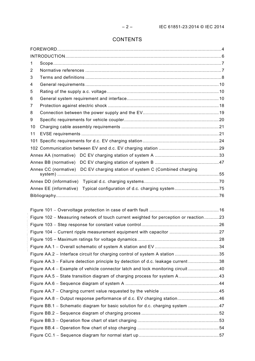
– 2 – IEC 61851-23:2014 © IEC 2014 CONTENTS FOREWORD ........................................................................................................................... 4 INTRODUCTION ..................................................................................................................... 6 1 Scope .............................................................................................................................. 7 2 Normative references ...................................................................................................... 7 3 Terms and definitions ...................................................................................................... 8 4 General requirements .................................................................................................... 10 5 Rating of the supply a.c. voltage .................................................................................... 10 6 General system requirement and interface..................................................................... 10 7 Protection against electric shock ................................................................................... 18 8 Connection between the power supply and the EV......................................................... 19 9 Specific requirements for vehicle coupler ....................................................................... 20 10 Charging cable assembly requirements ......................................................................... 21 11 EVSE requirements ....................................................................................................... 21 101 Specific requirements for d.c. EV charging station ......................................................... 24 102 Communication between EV and d.c. EV charging station ............................................. 29 Annex AA (normative) DC EV charging station of system A ................................................ 33 Annex BB (normative) DC EV charging station of system B ................................................ 47 Annex CC (normative) DC EV charging station of system C (Combined charging system) ......................................................................................................................... 55 Annex DD (informative) Typical d.c. charging systems ........................................................ 70 Annex EE (informative) Typical configuration of d.c. charging system ................................. 75 Bibliography .......................................................................................................................... 76 Figure 101 − Overvoltage protection in case of earth fault .................................................... 16 Figure 102 − Measuring network of touch current weighted for perception or reaction ........... 23 Figure 103 − Step response for constant value control .......................................................... 26 Figure 104 − Current ripple measurement equipment with capacitor ..................................... 27 Figure 105 – Maximum ratings for voltage dynamics ............................................................. 28 Figure AA.1 − Overall schematic of system A station and EV ................................................ 34 Figure AA.2 − Interface circuit for charging control of system A station ................................. 35 Figure AA.3 − Failure detection principle by detection of d.c. leakage current ....................... 38 Figure AA.4 − Example of vehicle connector latch and lock monitoring circuit ....................... 40 Figure AA.5 − State transition diagram of charging process for system A .............................. 43 Figure AA.6 − Sequence diagram of system A ...................................................................... 44 Figure AA.7 − Charging current value requested by the vehicle ............................................ 45 Figure AA.8 − Output response performance of d.c. EV charging station ............................... 46 Figure BB.1 − Schematic diagram for basic solution for d.c. charging system ....................... 47 Figure BB.2 − Sequence diagram of charging process .......................................................... 52 Figure BB.3 − Operation flow chart of start charging ............................................................. 53 Figure BB.4 − Operation flow chart of stop charging ............................................................. 54 Figure CC.1 − Sequence diagram for normal start up ............................................................ 57 --```,```,,,`,`,,`,```,```,,,,`,-`-`,,`,,`,`,,`---
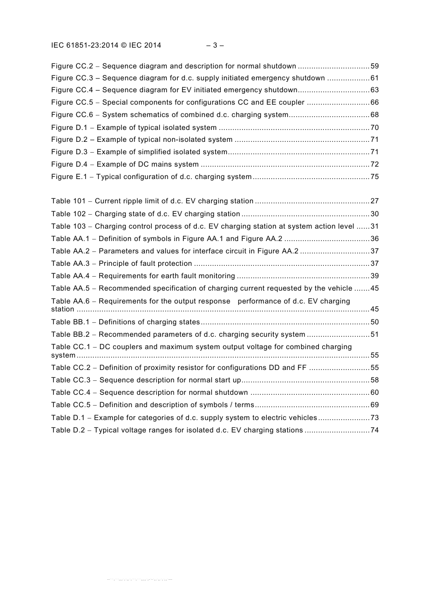
IEC 61851-23:2014 © IEC 2014 – 3 – Figure CC.2 − Sequence diagram and description for normal shutdown ................................ 59 Figure CC.3 – Sequence diagram for d.c. supply initiated emergency shutdown ................... 61 Figure CC.4 – Sequence diagram for EV initiated emergency shutdown................................ 63 Figure CC.5 − Special components for configurations CC and EE coupler ............................ 66 Figure CC.6 − System schematics of combined d.c. charging system.................................... 68 Figure D.1 − Example of typical isolated system ................................................................... 70 Figure D.2 – Example of typical non-isolated system ............................................................ 71 Figure D.3 − Example of simplified isolated system ............................................................... 71 Figure D.4 − Example of DC mains system ........................................................................... 72 Figure E.1 − Typical configuration of d.c. charging system .................................................... 75 Table 101 − Current ripple limit of d.c. EV charging station ................................................... 27 Table 102 − Charging state of d.c. EV charging station ......................................................... 30 Table 103 − Charging control process of d.c. EV charging station at system action level ...... 31 Table AA.1 − Definition of symbols in Figure AA.1 and Figure AA.2 ...................................... 36 Table AA.2 − Parameters and values for interface circuit in Figure AA.2 ............................... 37 Table AA.3 − Principle of fault protection .............................................................................. 37 Table AA.4 − Requirements for earth fault monitoring ........................................................... 39 Table AA.5 − Recommended specification of charging current requested by the vehicle ....... 45 Table AA.6 − Requirements for the output response performance of d.c. EV charging station .................................................................................................................................. 45 Table BB.1 − Definitions of charging states ........................................................................... 50 Table BB.2 − Recommended parameters of d.c. charging security system ............................ 51 Table CC.1 − DC couplers and maximum system output voltage for combined charging system .................................................................................................................................. 55 Table CC.2 − Definition of proximity resistor for configurations DD and FF ........................... 55 Table CC.3 − Sequence description for normal start up ......................................................... 58 Table CC.4 − Sequence description for normal shutdown ..................................................... 60 Table CC.5 − Definition and description of symbols / terms ................................................... 69 Table D.1 − Example for categories of d.c. supply system to electric vehicles ....................... 73 Table D.2 − Typical voltage ranges for isolated d.c. EV charging stations ............................. 74 --```,```,,,`,`,,`,```,```,,,,`,-`-`,,`,,`,`,,`---
– 4 – IEC 61851-23:2014 © IEC 2014 INTERNATIONAL ELECTROTECHNICAL COMMISSION ____________ ELECTRIC VEHICLE CONDUCTIVE CHARGING SYSTEM – Part 23: DC electric vehicle charging station FOREWORD 1) The International Electrotechnical Commission (IEC) is a worldwide organization for standardization comprising all national electrotechnical committees (IEC National Committees). The object of IEC is to promote international co-operation on all questions concerning standardization in the electrical and electronic fields. To this end and in addition to other activities, IEC publishes International Standards, Technical Specifications, Technical Reports, Publicly Available Specifications (PAS) and Guides (hereafter referred to as “IEC Publication(s)”). Their preparation is entrusted to technical committees; any IEC National Committee interested in the subject dealt with may participate in this preparatory work. International, governmental and non- governmental organizations liaising with the IEC also participate in this preparation. IEC collaborates closely with the International Organization for Standardization (ISO) in accordance with conditions determined by agreement between the two organizations. 2) The formal decisions or agreements of IEC on technical matters express, as nearly as possible, an international consensus of opinion on the relevant subjects since each technical committee has representation from all interested IEC National Committees. 3) IEC Publications have the form of recommendations for international use and are accepted by IEC National Committees in that sense. While all reasonable efforts are made to ensure that the technical content of IEC Publications is accurate, IEC cannot be held responsible for the way in which they are used or for any misinterpretation by any end user. 4) In order to promote international uniformity, IEC National Committees undertake to apply IEC Publications transparently to the maximum extent possible in their national and regional publications. Any divergence between any IEC Publication and the corresponding national or regional publication shall be clearly indicated in the latter. 5) IEC itself does not provide any attestation of conformity. Independent certification bodies provide conformity assessment services and, in some areas, access to IEC marks of conformity. IEC is not responsible for any services carried out by independent certification bodies. 6) All users should ensure that they have the latest edition of this publication. 7) No liability shall attach to IEC or its directors, employees, servants or agents including individual experts and members of its technical committees and IEC National Committees for any personal injury, property damage or other damage of any nature whatsoever, whether direct or indirect, or for costs (including legal fees) and expenses arising out of the publication, use of, or reliance upon, this IEC Publication or any other IEC Publications. 8) Attention is drawn to the Normative references cited in this publication. Use of the referenced publications is indispensable for the correct application of this publication. 9) Attention is drawn to the possibility that some of the elements of this IEC Publication may be the subject of patent rights. IEC shall not be held responsible for identifying any or all such patent rights. International Standard IEC 61851-23 has been prepared by IEC technical committee 69: Electric road vehicles and electric industrial trucks. The text of this standard is based on the following documents: FDIS 69/272/FDIS Report on voting 69/279/RVD Full information on the voting for the approval of this standard can be found in the report on voting indicated in the above table. This publication has been drafted in accordance with the ISO/IEC Directives, Part 2. This standard is to be read in conjunction with IEC 61851-1:2010. It was established on the basis of the second edition (2010) of that standard. --```,```,,,`,`,,`,```,```,,,,`,-`-`,,`,,`,`,,`---
IEC 61851-23:2014 © IEC 2014 – 5 – The clauses of particular requirements the corresponding clauses in IEC 61851-1:2010. Where the text of subsequent clauses indicates an "addition" to or a "replacement" of the relevant requirement, test specification or explanation of Part 1, these changes are made to the relevant text of Part 1, which then becomes part of this standard. Where no change is necessary, the words "This clause of Part 1 is applicable" are used. Additional clauses, tables and figures which are not included in Part 1, have a number starting from 101. Additional annexes are lettered AA, BB etc. this standard supplement or modify in A list of all parts in the IEC 61851 series, published under the general title Electric vehicle conductive charging system, can be found on the IEC website. In this standard, the following print types are used: test specifications and instructions regarding application of Part 1: italic type. – – notes: smaller roman type. The committee has decided that the contents of this publication will remain unchanged until the stability date indicated on the IEC web site under "http://webstore.iec.ch" in the data related to the specific publication. At this date, the publication will be reconfirmed, • • withdrawn, • • amended. replaced by a revised edition, or it contains colours which are considered IMPORTANT – The 'colour inside' logo on the cover page of this publication indicates that for the correct understanding of its contents. Users should therefore print this document using a colour printer. to be useful --```,```,,,`,`,,`,```,```,,,,`,-`-`,,`,,`,`,,`---
– 6 – IEC 61851-23:2014 © IEC 2014 INTRODUCTION to The introduction and commercialisation of electric vehicles has been accelerated in the global the global concerns on CO2 reduction and energy security. market, responding Concurrently, the development of charging infrastructure for electric vehicles has also been expanding. As a complement to the a.c. charging system, d.c. charging is recognized as an effective solution to extend the available range of electric vehicles. The international standardization of charging infrastructure is indispensable for the diffusion of electric vehicles, and this standard is developed for the manufacturers’ convenience by providing general and basic requirements for d.c. EV charging stations for conductive connection to the vehicle. --```,```,,,`,`,,`,```,```,,,,`,-`-`,,`,,`,`,,`---
分享到:
收藏