UML 2.0
UML 2.0
“Fundamentals”
“Fundamentals”
UML 2.0 “Fundamentals”
What is UML?
How do we capture requirements using UML?
How do we describe structure using UML?
How do we model communication using UML?
How do we describe behavior using UML?
UML 2.0 "Fundamentals" © Telelogic 1999-2005 5/16/2005
UML-1.1
www.Telelogic.com
UML 2.0 "Fundamentals" © Telelogic 1999-2005 5/16/2005
UML-1.2
www.Telelogic.com
What‘s not UML
What is UML?
What is UML?
The UML is not a method…
A method is a comprehensive and consistent
collection of the following 3 elements
Modeling language - the language or notation used to convey ideas
in both the problem domain (analysis) and the solution domain
(design)
Modeling heuristics - Describes how the modeling language can be
used in specific situations
Work organization or Process - A framework for organizing and
performing development work (the process)
� The UML is a modelling language
UML 2.0 "Fundamentals" © Telelogic 1999-2005 5/16/2005
UML-1.3
www.Telelogic.com
UML 2.0 "Fundamentals" © Telelogic 1999-2005 5/16/2005
UML-1.4
www.Telelogic.com
�
So… What is UML?
Unified Modeling Language
Comprehensive full life-cycle 3rd Generation modeling
language
Standardized in 1997 by the OMG
Created by a consortium of 12 companies from various domains
I-Logix a key contributor to behavioral modeling
Incorporates state of the art Software and Systems A&D
concepts
Matches the growing complexity of real-time systems
Large scale systems, Networking, Web enabling, Data management
Extensible and configurable
Unprecedented inter-disciplinary market penetration
UML 2.0 is latest version in the process of being released
Advent of the UML
UML 0.6 - Dr David Harel adds Statecharts
UML 0.9 & 0.91
Released
OMG Issues RFP
Ivar Jacobson
(Objectory) join
them and add
OOSE
RFP Response
for UML 1.0
UML 1.1
UML 1.3
Grady Booch and
Jim Rumbaugh
begin unifying
Booch & OMT
Methods begin to
merge
No Of Identifiable OO
Modelling Languages
Increases from <10 to >50
“Method Wars” Begin!
Identifiable OO
modelling
languages began
to appear
UML 1.4
UML 2.0
Mid 70s – Late 80s
1989
1994
1995
1996
1997
1999
2001
2005+
2005+
OOSE = Object Oriented Software Engineering Method
OMT = Object Modelling Technique
UML 2.0 "Fundamentals" © Telelogic 1999-2005 5/16/2005
UML-1.5
www.Telelogic.com
UML 2.0 "Fundamentals" © Telelogic 1999-2005 5/16/2005
UML-1.6
www.Telelogic.com
UML 2.0 Diagrams
Package
Diagrams
Class
Diagrams
Activity
Diagrams
Structural
Diagrams
Behavioral
Diagrams
Interaction
Diagrams
Structure
Diagrams
Object
Diagrams
Deployment
Diagrams
Component
Diagrams
State Machine
Diagrams
Use Case
Diagrams
Timing
Diagrams
Communication
Diagrams
Sequence
Diagrams
Interaction
Diagrams
Use Case Diagram
This diagram shows what the system does and who uses it.
UML 2.0 "Fundamentals" © Telelogic 1999-2005 5/16/2005
UML-1.7
www.Telelogic.com
UML 2.0 "Fundamentals" © Telelogic 1999-2005 5/16/2005
UML-1.8
www.Telelogic.com
�
Sequence Diagram
Class Diagram
Sequence Diagrams show how instances communicate over time.
Class diagrams show classes and relations between them.
UML 2.0 "Fundamentals" © Telelogic 1999-2005 5/16/2005
UML-1.9
www.Telelogic.com
UML 2.0 "Fundamentals" © Telelogic 1999-2005 5/16/2005
UML-1.10
www.Telelogic.com
Object Diagram
Structure Diagram
Object Diagrams show instances of classes and show which
ones are linked to others at run time.
This diagram shows the internal structure of classes.
UML 2.0 "Fundamentals" © Telelogic 1999-2005 5/16/2005
UML-1.11
www.Telelogic.com
UML 2.0 "Fundamentals" © Telelogic 1999-2005 5/16/2005
UML-1.12
www.Telelogic.com
�
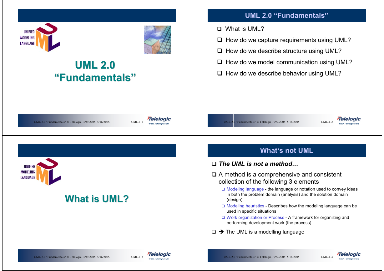
State Machine Diagram
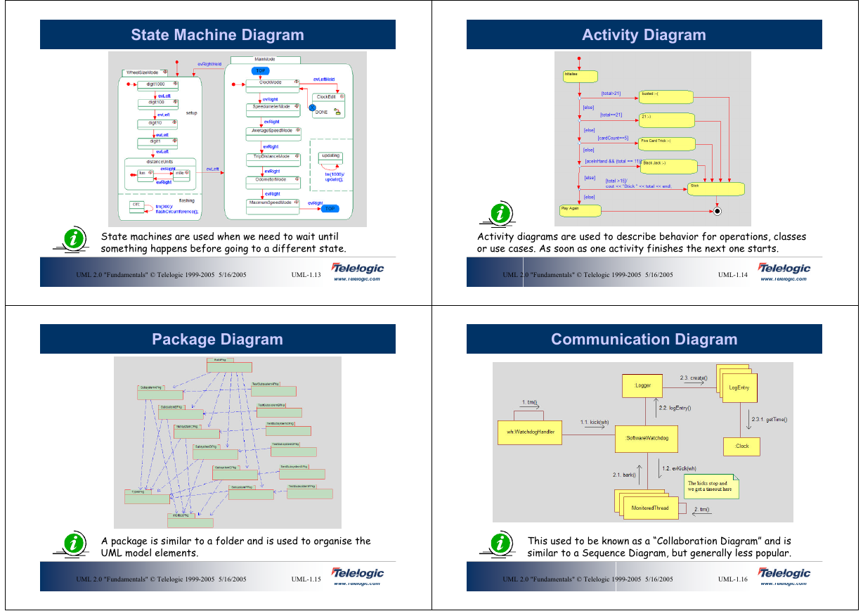
Activity Diagram
State machines are used when we need to wait until
something happens before going to a different state.
Activity diagrams are used to describe behavior for operations, classes
or use cases. As soon as one activity finishes the next one starts.
UML 2.0 "Fundamentals" © Telelogic 1999-2005 5/16/2005
UML-1.13
www.Telelogic.com
UML 2.0 "Fundamentals" © Telelogic 1999-2005 5/16/2005
UML-1.14
www.Telelogic.com
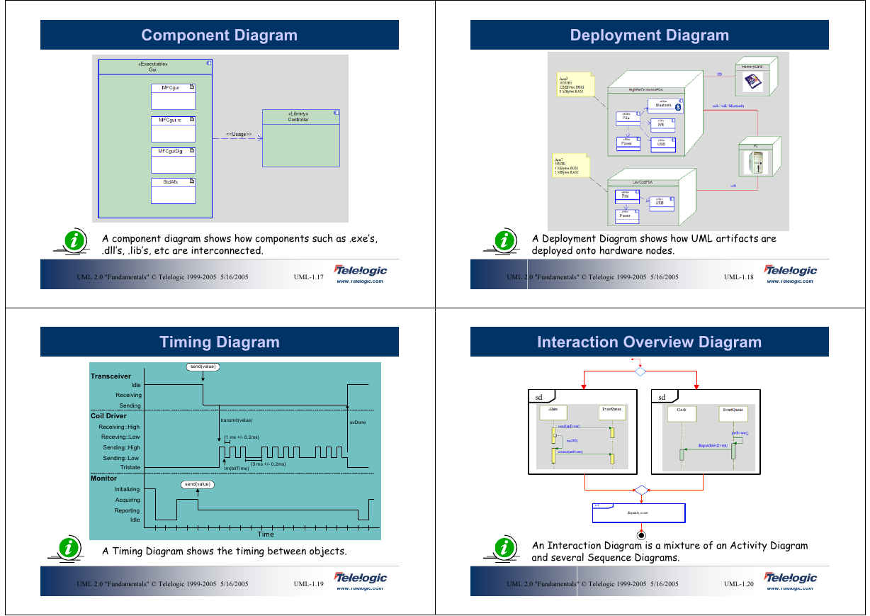
Package Diagram
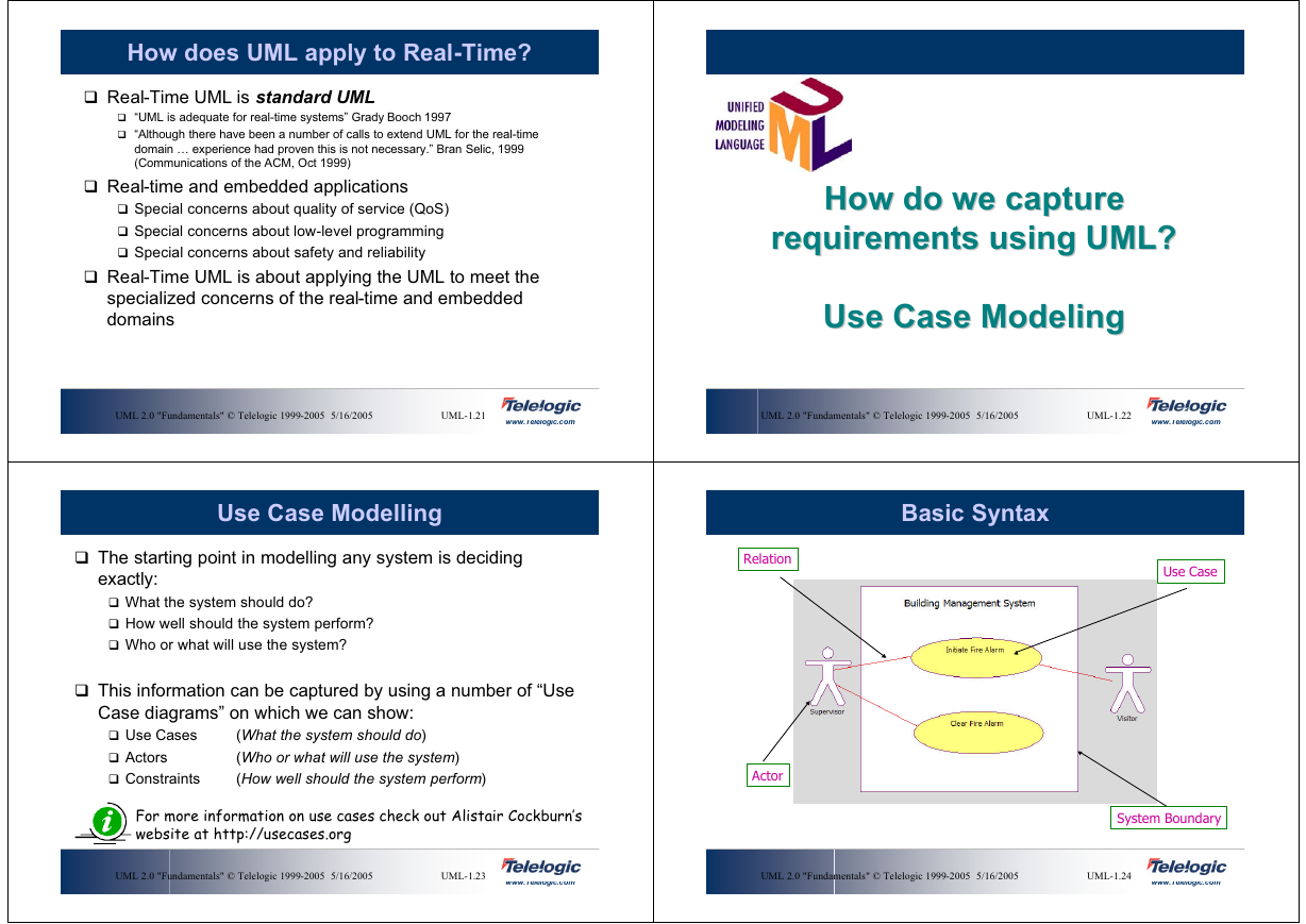
Communication Diagram
A package is similar to a folder and is used to organise the
UML model elements.
This used to be known as a “Collaboration Diagram” and is
similar to a Sequence Diagram, but generally less popular.
UML 2.0 "Fundamentals" © Telelogic 1999-2005 5/16/2005
UML-1.15
www.Telelogic.com
UML 2.0 "Fundamentals" © Telelogic 1999-2005 5/16/2005
UML-1.16
www.Telelogic.com
�
Component Diagram
Deployment Diagram
A component diagram shows how components such as .exe’s,
.dll’s, .lib’s, etc are interconnected.
A Deployment Diagram shows how UML artifacts are
deployed onto hardware nodes.
UML 2.0 "Fundamentals" © Telelogic 1999-2005 5/16/2005
UML-1.17
www.Telelogic.com
UML 2.0 "Fundamentals" © Telelogic 1999-2005 5/16/2005
UML-1.18
www.Telelogic.com
Timing Diagram
send(value)
transmit(value)
{1 ms +/- 0.2ms}
evDone
tm(bitTime)
{3 ms +/- 0.2ms}
send(value)
Transceiver
Idle
Receiving
Sending
Coil Driver
Receiving::High
Receving::Low
Sending::High
Sending::Low
Tristate
Monitor
Initializing
Acquiring
Reporting
Idle
A Timing Diagram shows the timing between objects.
Time
Interaction Overview Diagram
sd
sd
ref
dispatch_event
An Interaction Diagram is a mixture of an Activity Diagram
and several Sequence Diagrams.
UML 2.0 "Fundamentals" © Telelogic 1999-2005 5/16/2005
UML-1.19
www.Telelogic.com
UML 2.0 "Fundamentals" © Telelogic 1999-2005 5/16/2005
UML-1.20
www.Telelogic.com
�
How does UML apply to Real-Time?
Real-Time UML is standard UML
“UML is adequate for real-time systems” Grady Booch 1997
“Although there have been a number of calls to extend UML for the real-time
domain … experience had proven this is not necessary.” Bran Selic, 1999
(Communications of the ACM, Oct 1999)
Real-time and embedded applications
Special concerns about quality of service (QoS)
Special concerns about low-level programming
Special concerns about safety and reliability
Real-Time UML is about applying the UML to meet the
specialized concerns of the real-time and embedded
domains
How do we capture
How do we capture
requirements using UML?
requirements using UML?
Use Case Modeling
Use Case Modeling
UML 2.0 "Fundamentals" © Telelogic 1999-2005 5/16/2005
UML-1.21
www.Telelogic.com
UML 2.0 "Fundamentals" © Telelogic 1999-2005 5/16/2005
UML-1.22
www.Telelogic.com
Use Case Modelling
Basic Syntax
The starting point in modelling any system is deciding
exactly:
What the system should do?
How well should the system perform?
Who or what will use the system?
This information can be captured by using a number of “Use
Case diagrams” on which we can show:
Use Cases
Actors
Constraints
(What the system should do)
(Who or what will use the system)
(How well should the system perform)
Use Case
Relation
Actor
For more information on use cases check out Alistair Cockburn’s
website at http://usecases.org
System Boundary
UML 2.0 "Fundamentals" © Telelogic 1999-2005 5/16/2005
UML-1.23
www.Telelogic.com
UML 2.0 "Fundamentals" © Telelogic 1999-2005 5/16/2005
UML-1.24
www.Telelogic.com
�
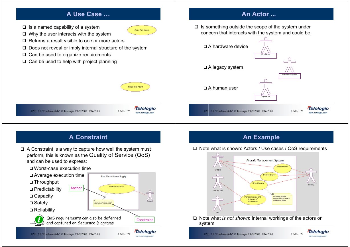
A Use Case …
An Actor ...
Is a named capability of a system
Why the user interacts with the system
Returns a result visible to one or more actors
Does not reveal or imply internal structure of the system
Can be used to organize requirements
Can be used to help with project planning
Is something outside the scope of the system under
concern that interacts with the system and could be:
A hardware device
A legacy system
A human user
FireAlarm
Supervisor
AlarmSubSystem
UML 2.0 "Fundamentals" © Telelogic 1999-2005 5/16/2005
UML-1.25
www.Telelogic.com
UML 2.0 "Fundamentals" © Telelogic 1999-2005 5/16/2005
UML-1.26
www.Telelogic.com
A Constraint
An Example
Note what is shown: Actors / Use cases / QoS requirements
A Constraint is a way to capture how well the system must
perform, this is known as the Quality of Service (QoS)
and can be used to express:
Worst-case execution time
Average execution time
Throughput
Predictability
Capacity
Safety
Reliability
Anchor
QoS requirements can also be deferred
and captured on Sequence Diagrams
Constraint
Note what is not shown: Internal workings of the actors or
system
UML 2.0 "Fundamentals" © Telelogic 1999-2005 5/16/2005
UML-1.27
www.Telelogic.com
UML 2.0 "Fundamentals" © Telelogic 1999-2005 5/16/2005
UML-1.28
www.Telelogic.com
�
Examples of Use Cases
As the System gets
bigger, the use cases
get more abstract
and “high level”
Identifying Use Cases
Answer questions such as:
What are the primary functions of the system?
What are the secondary functions of the system?
With what must the system interface?
Why is the system being built?
Play each actor in turn and ask
What do I want out of this system?
Identify:
Capabilities (use cases)
Other context participants (actors)
Identifying Use Cases is not easy, since there are many
potential satisfactory solutions. This is an activity that is
best performed as a team.
UML 2.0 "Fundamentals" © Telelogic 1999-2005 5/16/2005
UML-1.29
www.Telelogic.com
UML 2.0 "Fundamentals" © Telelogic 1999-2005 5/16/2005
UML-1.30
www.Telelogic.com
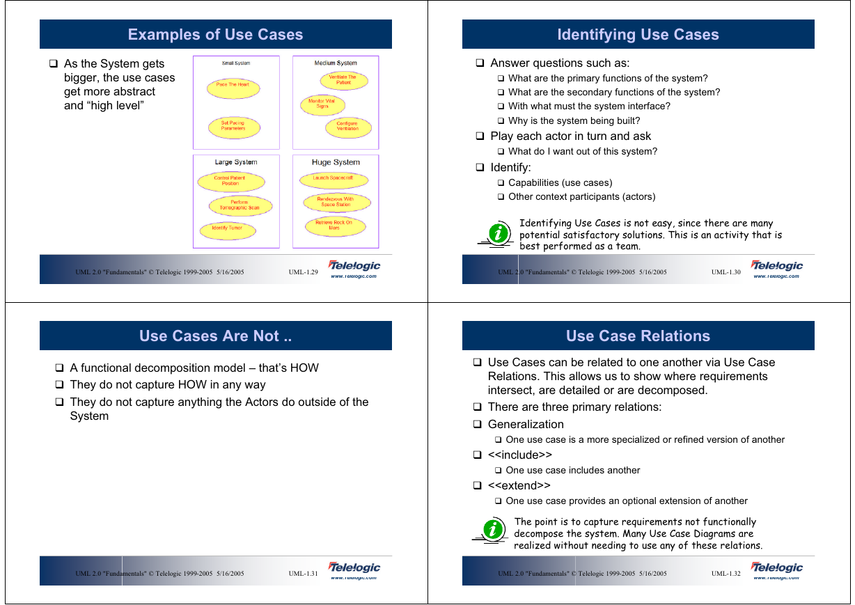
Use Cases Are Not ..
Use Case Relations
A functional decomposition model – that’s HOW
They do not capture HOW in any way
They do not capture anything the Actors do outside of the
System
Use Cases can be related to one another via Use Case
Relations. This allows us to show where requirements
intersect, are detailed or are decomposed.
There are three primary relations:
Generalization
One use case is a more specialized or refined version of another
<>
One use case includes another
<>
One use case provides an optional extension of another
The point is to capture requirements not functionally
decompose the system. Many Use Case Diagrams are
realized without needing to use any of these relations.
UML 2.0 "Fundamentals" © Telelogic 1999-2005 5/16/2005
UML-1.31
www.Telelogic.com
UML 2.0 "Fundamentals" © Telelogic 1999-2005 5/16/2005
UML-1.32
www.Telelogic.com
�




 2023年江西萍乡中考道德与法治真题及答案.doc
 2012年重庆南川中考生物真题及答案.doc
 2013年江西师范大学地理学综合及文艺理论基础考研真题.doc
 2020年四川甘孜小升初语文真题及答案I卷.doc
 2020年注册岩土工程师专业基础考试真题及答案.doc
 2023-2024学年福建省厦门市九年级上学期数学月考试题及答案.doc
 2021-2022学年辽宁省沈阳市大东区九年级上学期语文期末试题及答案.doc
 2022-2023学年北京东城区初三第一学期物理期末试卷及答案.doc
 2018上半年江西教师资格初中地理学科知识与教学能力真题及答案.doc
 2012年河北国家公务员申论考试真题及答案-省级.doc
 2020-2021学年江苏省扬州市江都区邵樊片九年级上学期数学第一次质量检测试题及答案.doc
 2022下半年黑龙江教师资格证中学综合素质真题及答案.doc