DATASHEET
AX5043
Advanced high performance
ASK and FSK narrow-band
transceiver for 70-1050 MHz
range
Version 1.7
�
2
Document
Type
Datasheet
Document
Status
Document
Version
Version 1.7
Product
AX5043
Version 1.7
Datasheet AX5043
�
Table of Contents 3
Table of Contents
1. Overview..................................................................................................... 6
1.1. Features ..................................................................................................... 6
1.2. Applications................................................................................................. 7
2. Block Diagram............................................................................................. 8
3. Pin Function Descriptions ........................................................................... 9
3.1. Pinout Drawing .......................................................................................... 10
4. Specifications............................................................................................ 11
4.1. Absolute Maximum Ratings .......................................................................... 11
4.2. DC Characteristics ...................................................................................... 12
Supplies .................................................................................................... 12
Logic......................................................................................................... 14
4.3. AC Characteristics ...................................................................................... 15
Crystal Oscillator ........................................................................................ 15
Low-power Oscillator ................................................................................... 15
RF Frequency Generation Subsystem (Synthesizer) ......................................... 16
Transmitter................................................................................................ 19
Receiver .................................................................................................... 20
SPI Timing................................................................................................. 21
Wire Mode Interface Timing.......................................................................... 22
General Purpose ADC (GPADC) ..................................................................... 22
5. Circuit Description .................................................................................... 23
5.1. Voltage Regulators ..................................................................................... 24
5.2. Crystal Oscillator ........................................................................................ 25
5.3. Low Power Oscillator and Wake on Radio (WOR) Mode..................................... 25
5.4. GPIO Pins.................................................................................................. 26
5.5. SYSCLK Output .......................................................................................... 26
Version 1.7
Datasheet AX5043
�
4
Table of Contents
5.6. Power-on-reset (POR) ................................................................................. 27
5.7. RF Frequency Generation Subsystem............................................................. 27
VCO.......................................................................................................... 27
VCO Auto-Ranging ...................................................................................... 28
Loop Filter and Charge Pump........................................................................ 28
Registers ................................................................................................... 29
5.8. RF Input and Output Stage (ANTP/ANTN/ANTP1) ............................................ 30
LNA .......................................................................................................... 30
PA ............................................................................................................ 30
5.9. Digital IF Channel Filter and Demodulator ...................................................... 31
Registers ................................................................................................... 31
5.10.
5.11.
Encoder ............................................................................................. 32
Framing and FIFO ............................................................................... 32
Packet Modes ............................................................................................. 33
RAW Modes................................................................................................ 34
5.12.
5.13.
5.14.
5.15.
5.16.
RX AGC and RSSI................................................................................ 34
Modulator .......................................................................................... 35
Automatic Frequency Control (AFC) ....................................................... 35
PWRMODE Register ............................................................................. 36
Serial Peripheral Interface (SPI) ............................................................ 38
SPI Timing................................................................................................. 39
5.17. Wire Mode Interface ............................................................................ 40
Wire Mode Timing ....................................................................................... 40
General Purpose ADC (GPADC) ..................................................................... 41
Σ∆ DAC...................................................................................................... 41
6. Register Bank Description......................................................................... 42
6.1. Control Register Map................................................................................... 43
7. Application Information ............................................................................ 55
7.1. Typical Application Diagrams........................................................................ 55
Version 1.7
Datasheet AX5043
�
Table of Contents 5
Match to 50 Ohm for differential antenna pins (868/915/433/169 MHz RX/TX
operation) ................................................................................................. 55
Match to 50 Ohm for single-ended antenna pin (868/915/433 TX operation) ....... 56
Match to 50 Ohm for single-ended antenna pin (169 MHz TX operation) ............. 57
Using a Dipole Antenna and the internal TX/RX Switch ..................................... 58
Using a single-ended Antenna and the internal TX/RX Switch ............................ 59
Using an external high-power PA and an external TX/RX Switch ........................ 60
Using the single-ended PA............................................................................ 61
Using two Antenna...................................................................................... 62
Using an external VCO inductor .................................................................... 63
Using an external VCO................................................................................. 64
Using a TCXO ............................................................................................. 65
8. QFN28 Package Information ..................................................................... 66
8.1. Package Outline QFN28 ............................................................................... 66
8.2. QFN28 Soldering Profile............................................................................... 67
8.3. QFN28 Recommended Pad Layout................................................................. 68
8.4. Assembly Process ....................................................................................... 68
Stencil Design & Solder Paste Application ....................................................... 68
9. Life Support Applications .......................................................................... 70
10. Contact Information.................................................................................. 71
Version 1.7
Datasheet AX5043
�
6
Overview
1. Overview
1.1. Features
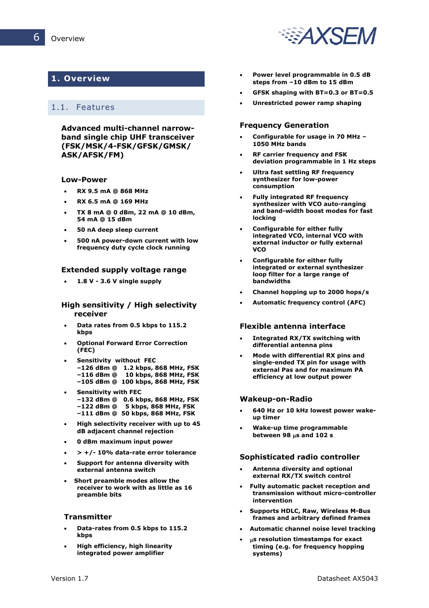
Advanced multi-channel narrow-
band single chip UHF transceiver
(FSK/MSK/4-FSK/GFSK/GMSK/
ASK/AFSK/FM)
Low-Power
• RX 9.5 mA @ 868 MHz
• RX 6.5 mA @ 169 MHz
•
•
•
TX 8 mA @ 0 dBm, 22 mA @ 10 dBm,
54 mA @ 15 dBm
50 nA deep sleep current
500 nA power-down current with low
frequency duty cycle clock running
Extended supply voltage range
•
1.8 V - 3.6 V single supply
High sensitivity / High selectivity
receiver
• Data rates from 0.5 kbps to 115.2
kbps
• Optional Forward Error Correction
(FEC)
•
•
Sensitivity without FEC
–126 dBm @ 1.2 kbps, 868 MHz, FSK
–116 dBm @ 10 kbps, 868 MHz, FSK
–105 dBm @ 100 kbps, 868 MHz, FSK
Sensitivity with FEC
–132 dBm @ 0.6 kbps, 868 MHz, FSK
–122 dBm @ 5 kbps, 868 MHz, FSK
–111 dBm @ 50 kbps, 868 MHz, FSK
• High selectivity receiver with up to 45
dB adjacent channel rejection
•
0 dBm maximum input power
• > +/- 10% data-rate error tolerance
•
Support for antenna diversity with
external antenna switch
• Short preamble modes allow the
receiver to work with as little as 16
preamble bits
Transmitter
• Data-rates from 0.5 kbps to 115.2
kbps
• High efficiency, high linearity
integrated power amplifier
•
Power level programmable in 0.5 dB
steps from –10 dBm to 15 dBm
• GFSK shaping with BT=0.3 or BT=0.5
• Unrestricted power ramp shaping
Frequency Generation
•
Configurable for usage in 70 MHz –
1050 MHz bands
• RF carrier frequency and FSK
deviation programmable in 1 Hz steps
• Ultra fast settling RF frequency
synthesizer for low-power
consumption
•
•
•
Fully integrated RF frequency
synthesizer with VCO auto-ranging
and band-width boost modes for fast
locking
Configurable for either fully
integrated VCO, internal VCO with
external inductor or fully external
VCO
Configurable for either fully
integrated or external synthesizer
loop filter for a large range of
bandwidths
•
Channel hopping up to 2000 hops/s
• Automatic frequency control (AFC)
Flexible antenna interface
•
Integrated RX/TX switching with
differential antenna pins
• Mode with differential RX pins and
single-ended TX pin for usage with
external Pas and for maximum PA
efficiency at low output power
Wakeup-on-Radio
•
640 Hz or 10 kHz lowest power wake-
up timer
• Wake-up time programmable
between 98 µs and 102 s
Sophisticated radio controller
• Antenna diversity and optional
external RX/TX switch control
• Fully automatic packet reception and
transmission without micro-controller
intervention
• Supports HDLC, Raw, Wireless M-Bus
frames and arbitrary defined frames
• Automatic channel noise level tracking
• µs resolution timestamps for exact
timing (e.g. for frequency hopping
systems)
Version 1.7
Datasheet AX5043
�
Table of Contents 7
15.245, EN 300 220 V2.3.1 including
the narrow-band 12.5 kHz, 20 kHz
and 25 kHz definitions.
• Security applications
• Messaging / paging
• Wireless sensors
• Wireless M-Bus applications
according to EN 13757-4
• 256 Byte micro-programmable FIFO,
optionally supports packet sizes >
256 Bytes
• 3 matching units for preamble byte,
sync-word and address
• Ability to store RSSI, frequency offset
and data-rate offset with the packet
data
• Multiple receiver parameter sets allow
the use of more aggressive receiver
parameters during preamble,
dramatically shortening the required
preamble length at no sensitivity
degradation
Advanced Crystal Oscillator
•
Fast start-up and lowest power
steady-state XTAL oscillator for a
wide range of crystals
•
•
Integrated crystal tuning capacitors
Possibility of applying an external
clock reference (TCXO)
Miscellaneous features
•
Few external components
•
•
•
SPI microcontroller interface
Extended AXSEM register set
Fully integrated current/voltage
references
• QFN28 package
Internal power-on-reset
Brown-out detection
10 bit 1MS/s General Purpose ADC
(GPADC)
•
•
•
1.2. Applications
70 – 1050 MHz licensed and unlicensed
radio systems.
• AMR
• FCC Part 90 6.25 kHz, 12.5 kHz and
25 kHz channel width, FCC Part
Version 1.7
Datasheet AX5043
�
8
Block Diagram
2. Block Diagram
1
C
D
A
P
G
2
C
D
A
P
G
25 26
AX5043
A
T
A
D
K
L
C
D
11
12
Mixer
LNA
IF Filter &
AGC PGAs
ANTP
ANTN
3
4
ANTP1
5
PA diff
PA se
ADC
AGC
Digital IF
channel
filter
De-
modulator
Modulator
n
o
i
t
c
e
r
r
o
C
r
o
r
r
E
d
r
a
w
r
o
F
r
e
d
o
c
n
E
i
g
n
m
a
r
F
r
e
l
l
o
r
t
n
o
C
o
d
a
R
i
t
e
k
c
a
p
d
n
a
g
n
m
i
i
t
g
n
i
l
d
n
a
h
O
F
I
F
FOUT
RF Frequency
Generation
Subsystem
RF Output
70 MHz–1GHz
FXTAL
Divider
13
8
9
10
K
L
C
S
Y
S
T
L
I
F
1
L
2
L
Chip configuration
POR
References
Low Power
Oscillator
640 Hz/10kHz
Communication Controller &
Serial Interface
Registers
Wake on Radio
SPI
Voltage
Regulator
1,7
23
A
N
A
_
D
D
V
O
I
_
D
D
V
19
20
21
14
15
16
17
P
M
A
R
W
P
L
E
S
T
N
A
Q
R
I
L
E
S
K
L
C
O
S
I
M
I
S
O
M
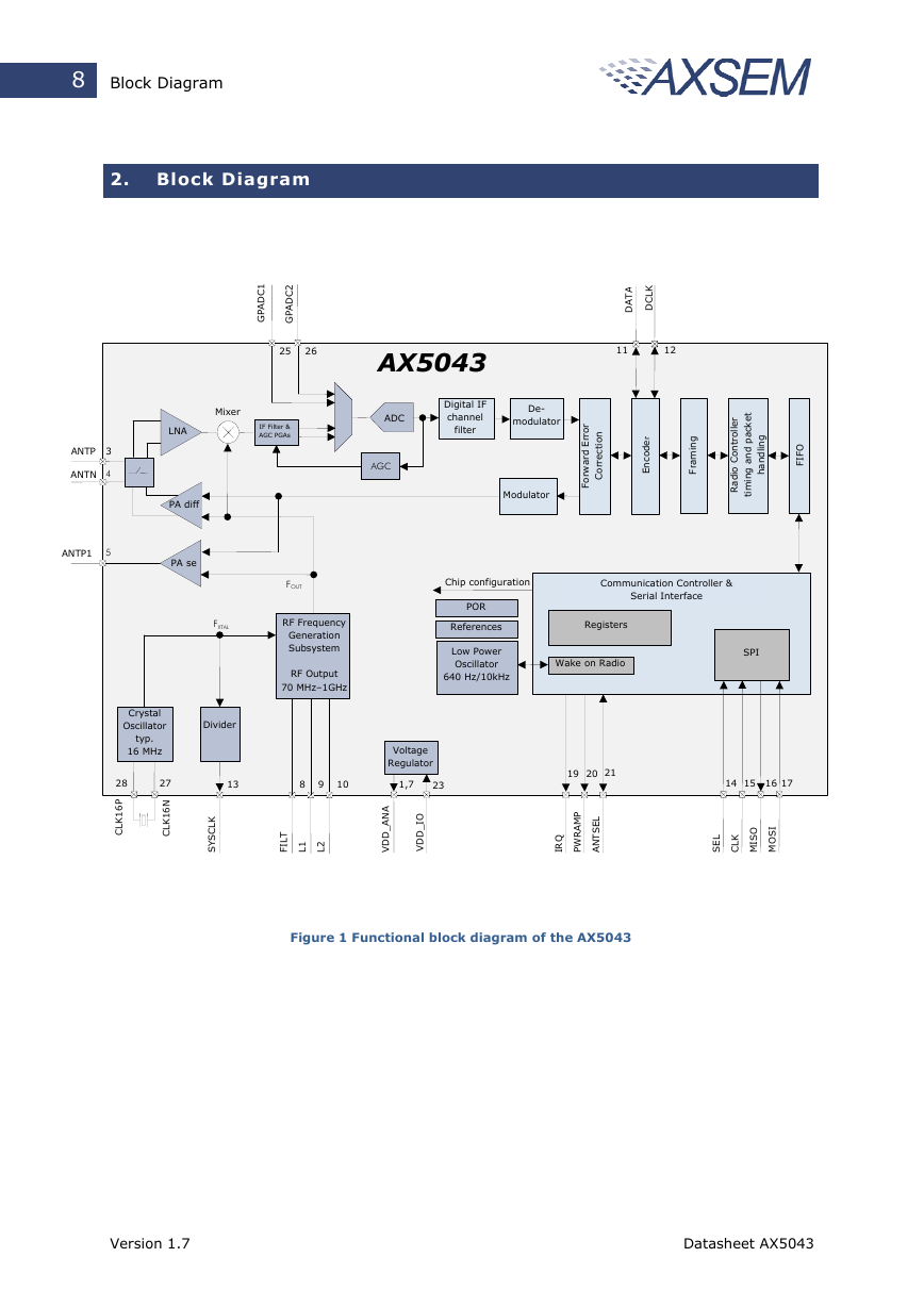
Figure 1 Functional block diagram of the AX5043
Crystal
Oscillator
typ.
16 MHz
28
P
6
1
K
L
C
27
N
6
1
K
L
C
Version 1.7
Datasheet AX5043
�




 2023年江西萍乡中考道德与法治真题及答案.doc
 2012年重庆南川中考生物真题及答案.doc
 2013年江西师范大学地理学综合及文艺理论基础考研真题.doc
 2020年四川甘孜小升初语文真题及答案I卷.doc
 2020年注册岩土工程师专业基础考试真题及答案.doc
 2023-2024学年福建省厦门市九年级上学期数学月考试题及答案.doc
 2021-2022学年辽宁省沈阳市大东区九年级上学期语文期末试题及答案.doc
 2022-2023学年北京东城区初三第一学期物理期末试卷及答案.doc
 2018上半年江西教师资格初中地理学科知识与教学能力真题及答案.doc
 2012年河北国家公务员申论考试真题及答案-省级.doc
 2020-2021学年江苏省扬州市江都区邵樊片九年级上学期数学第一次质量检测试题及答案.doc
 2022下半年黑龙江教师资格证中学综合素质真题及答案.doc