Adafruit I2S MEMS Microphone Breakout
Created by lady ada
Last updated on 2020-04-21 05:52:19 PM EDT
�
Overview
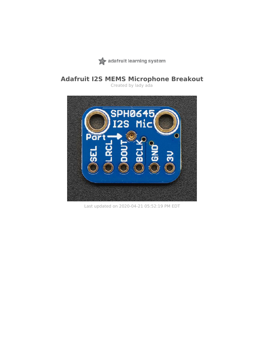
For many microcontrollers, adding audio input is easy with one of our analog microphone
breakouts (http://adafru.it/1063). But as you get to bigger and better microcontrollers and microcomputers, you'll find
that you don't always have an analog input, or maybe you want to avoid the noise that can seep in with an analog mic
system. Once you get past 8-bit micros, you will often find an I2S peripheral, that can take digital audio data in! That's
where this I2S Microphone Breakout comes in.
Instead of an analog output, there are three digital pins: Clock, Data and Word-Select. When connected to your
microcontroller/computer, the 'I2S Master' will drive the clock and word-select pins at a high frequency and read out
the data from the microphone. No analog conversion required!
© Adafruit Industries
https://learn.adafruit.com/adafruit-i2s-mems-microphone-breakout
Page 3 of 27
�
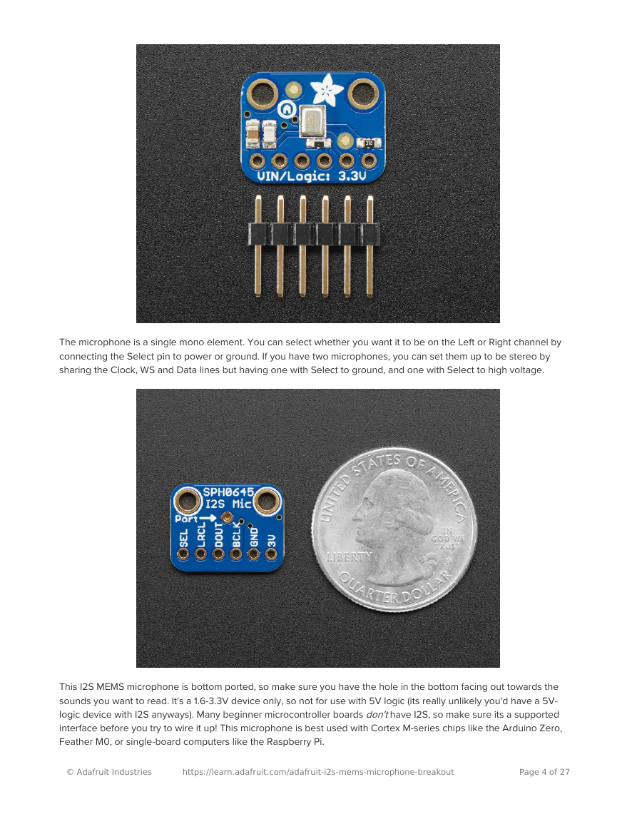
The microphone is a single mono element. You can select whether you want it to be on the Left or Right channel by
connecting the Select pin to power or ground. If you have two microphones, you can set them up to be stereo by
sharing the Clock, WS and Data lines but having one with Select to ground, and one with Select to high voltage.
This I2S MEMS microphone is bottom ported, so make sure you have the hole in the bottom facing out towards the
sounds you want to read. It's a 1.6-3.3V device only, so not for use with 5V logic (its really unlikely you'd have a 5V-
logic device with I2S anyways). Many beginner microcontroller boards don't have I2S, so make sure its a supported
interface before you try to wire it up! This microphone is best used with Cortex M-series chips like the Arduino Zero,
Feather M0, or single-board computers like the Raspberry Pi.
© Adafruit Industries
https://learn.adafruit.com/adafruit-i2s-mems-microphone-breakout
Page 4 of 27
�
© Adafruit Industries
https://learn.adafruit.com/adafruit-i2s-mems-microphone-breakout
Page 5 of 27
�
Assembly
Assembly is really easy, you can use straight or 'right-angle' style headers to attach to the PCB. We'll be using the plain
straight headers included
The board comes with all surface-mount components pre-soldered. The included header strip can be soldered on for
convenient use on a breadboard or with 0.1" connectors. You can also skip this step and solder on wires.
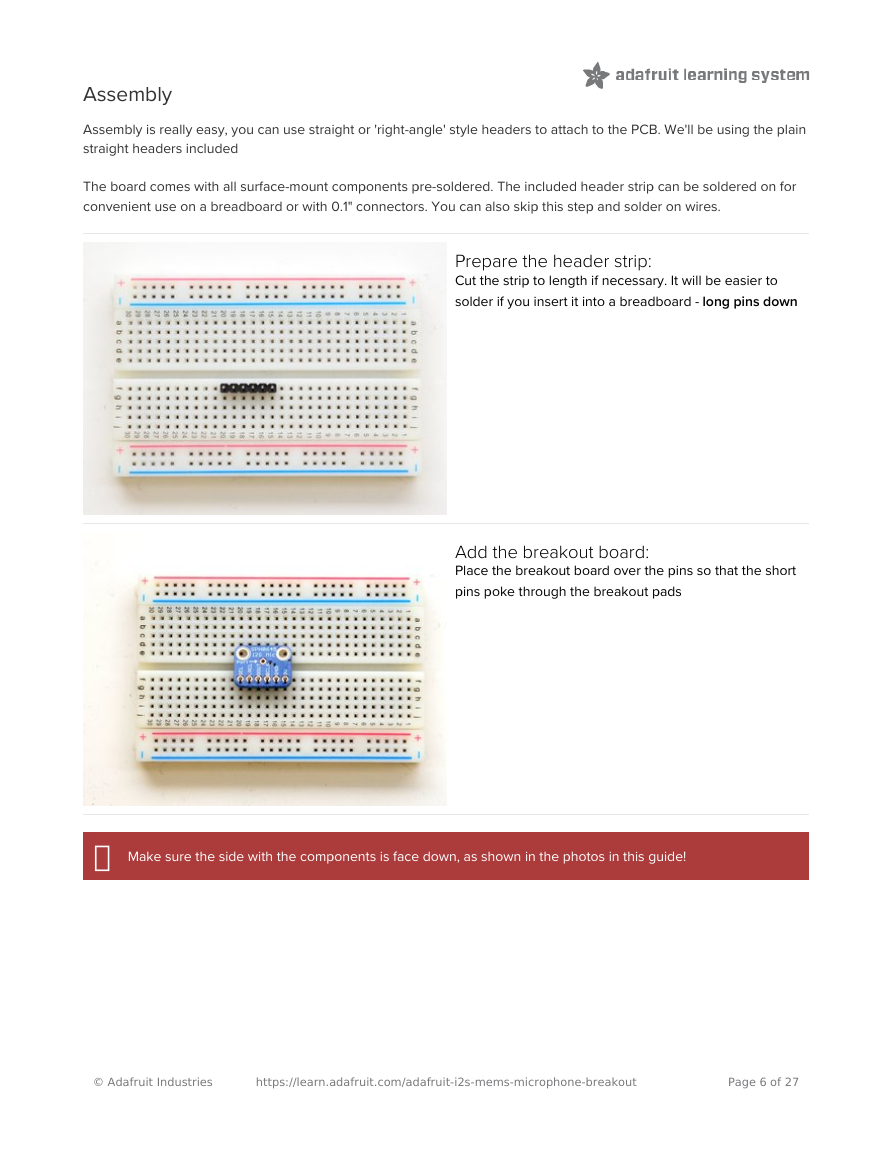
Prepare the header strip:
Cut the strip to length if necessary. It will be easier to
solder if you insert it into a breadboard - long pins down
Add the breakout board:
Place the breakout board over the pins so that the short
pins poke through the breakout pads
�
Make sure the side with the components is face down, as shown in the photos in this guide!
© Adafruit Industries
https://learn.adafruit.com/adafruit-i2s-mems-microphone-breakout
Page 6 of 27
�
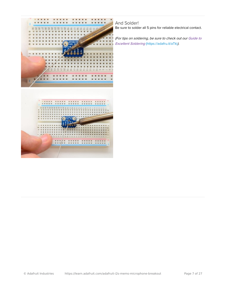
And Solder!
Be sure to solder all 5 pins for reliable electrical contact.
(For tips on soldering, be sure to check out our Guide to
Excellent Soldering (https://adafru.it/aTk)).
© Adafruit Industries
https://learn.adafruit.com/adafruit-i2s-mems-microphone-breakout
Page 7 of 27
�
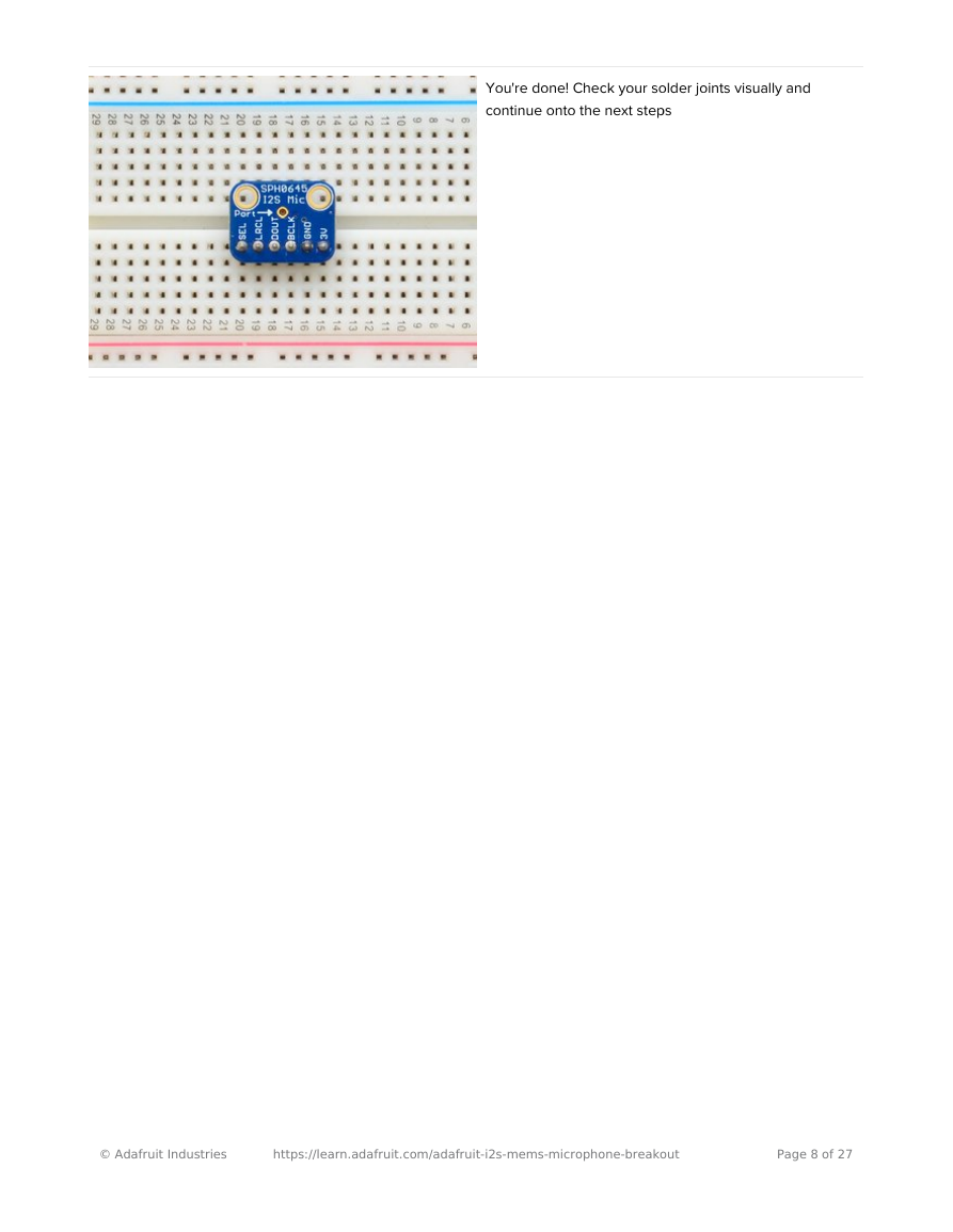
You're done! Check your solder joints visually and
continue onto the next steps
© Adafruit Industries
https://learn.adafruit.com/adafruit-i2s-mems-microphone-breakout
Page 8 of 27
�
Pinouts
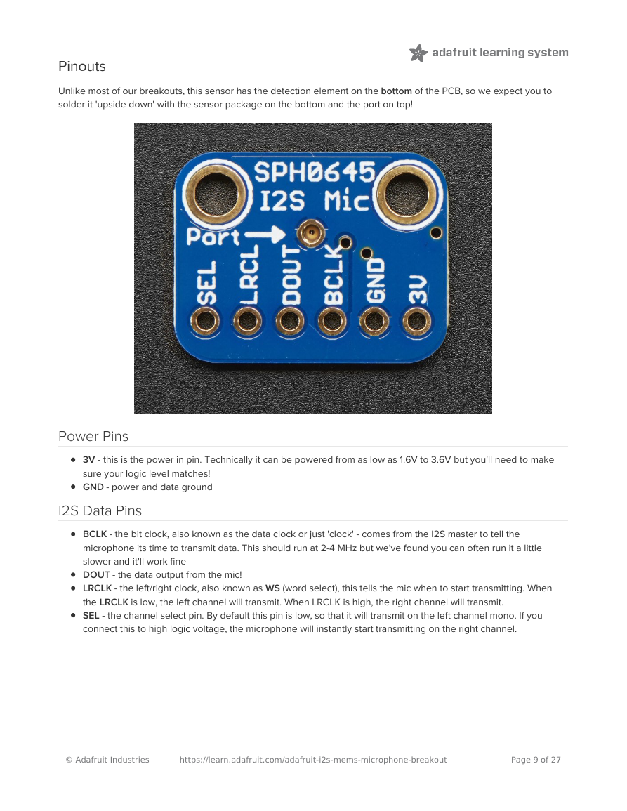
Unlike most of our breakouts, this sensor has the detection element on the bottom of the PCB, so we expect you to
solder it 'upside down' with the sensor package on the bottom and the port on top!
Power Pins
3V - this is the power in pin. Technically it can be powered from as low as 1.6V to 3.6V but you'll need to make
sure your logic level matches!
GND - power and data ground
I2S Data Pins
BCLK - the bit clock, also known as the data clock or just 'clock' - comes from the I2S master to tell the
microphone its time to transmit data. This should run at 2-4 MHz but we've found you can often run it a little
slower and it'll work fine
DOUT - the data output from the mic!
LRCLK - the left/right clock, also known as WS (word select), this tells the mic when to start transmitting. When
the LRCLK is low, the left channel will transmit. When LRCLK is high, the right channel will transmit.
SEL - the channel select pin. By default this pin is low, so that it will transmit on the left channel mono. If you
connect this to high logic voltage, the microphone will instantly start transmitting on the right channel.
© Adafruit Industries
https://learn.adafruit.com/adafruit-i2s-mems-microphone-breakout
Page 9 of 27
�




 2023年江西萍乡中考道德与法治真题及答案.doc
 2012年重庆南川中考生物真题及答案.doc
 2013年江西师范大学地理学综合及文艺理论基础考研真题.doc
 2020年四川甘孜小升初语文真题及答案I卷.doc
 2020年注册岩土工程师专业基础考试真题及答案.doc
 2023-2024学年福建省厦门市九年级上学期数学月考试题及答案.doc
 2021-2022学年辽宁省沈阳市大东区九年级上学期语文期末试题及答案.doc
 2022-2023学年北京东城区初三第一学期物理期末试卷及答案.doc
 2018上半年江西教师资格初中地理学科知识与教学能力真题及答案.doc
 2012年河北国家公务员申论考试真题及答案-省级.doc
 2020-2021学年江苏省扬州市江都区邵樊片九年级上学期数学第一次质量检测试题及答案.doc
 2022下半年黑龙江教师资格证中学综合素质真题及答案.doc