CHC2442-QPG
24GHz ISM SENSOR
Monolithic Microwave IC in SMD leadless package
Description
The CHC2442-QPG is a multifunction chip
which integrates a low phase noise VCO, Tx
MPA, two Gilbert based heterodyne Rx and a
switchable prescaler. The circuit is controlled
by SPI and monitored with power and
temperature sensor.
It is designed for signal generation and
reception for automotive radar applications.
It
package.
in RoHS compliant SMD
is supplied
Main Features
■ Frequency Band: 24-24.5GHz
■ >13dBm Max Tx Power
■ 12dB Tx Power control range
■ 37dB Rx gain
■ 24dB Rx gain control range
■ 11dB Rx SSB NF @ IF≥100kHz, max RF
gain
■ -16dBm IP1dB RF power @ min RF VGA
gain
■ Temperature range from -40°C to +125°C
■ DC bias: 3.3V / 205-225mA @ Pout @
stage 8-0
■ 28L-QFN4X5 SMD leadless package
■ MSL1
Main Electrical Characteristics
Tcase= +25°C
Symbol
Parameter
UMS
C2442
YYWW
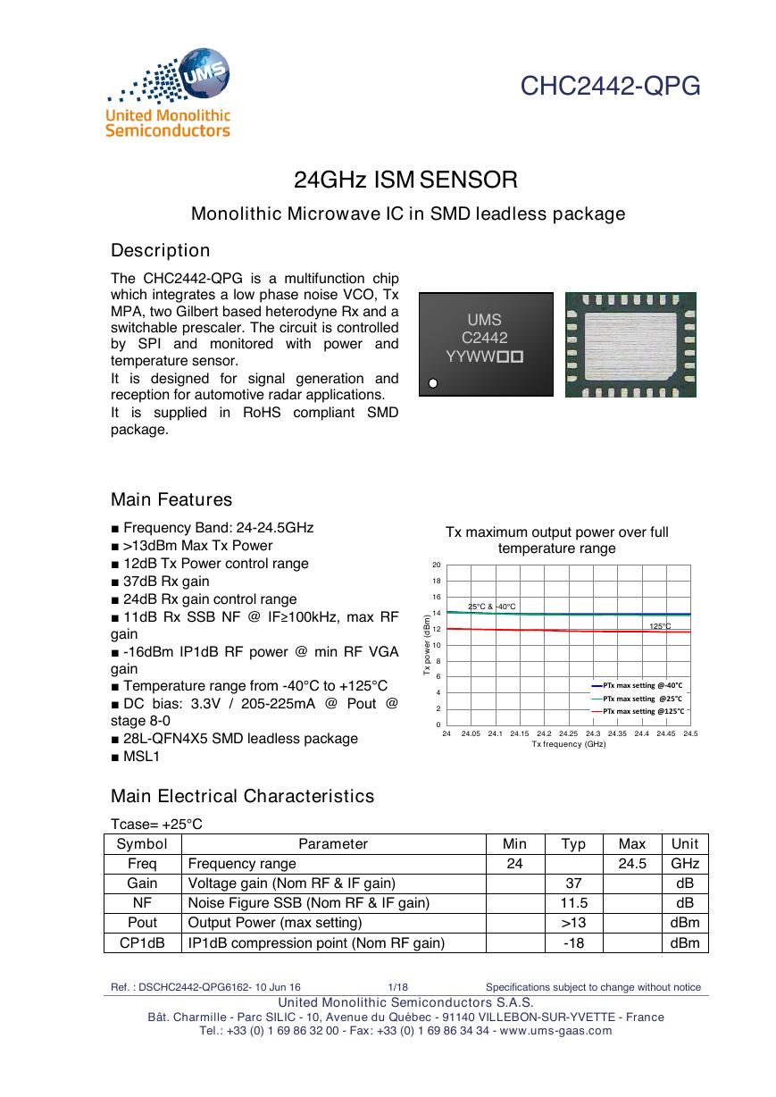
Tx maximum output power over full
temperature range
25°C & -40°C
125°C
Freq
Gain
NF
Pout
CP1dB
Frequency range
Voltage gain (Nom RF & IF gain)
Noise Figure SSB (Nom RF & IF gain)
Output Power (max setting)
IP1dB compression point (Nom RF gain)
Min
24
Typ
37
11.5
>13
-18
Max Unit
24.5 GHz
dB
dB
dBm
dBm
Ref. : DSCHC2442-QPG6162- 10 Jun 16
1/18
Specifications subject to change without notice
Bât. Charmille - Parc SILIC - 10, Avenue du Québec - 91140 VILLEBON-SUR-YVETTE - France
Tel.: +33 (0) 1 69 86 32 00 - Fax: +33 (0) 1 69 86 34 34 - www.ums-gaas.com
United Monolithic Semiconductors S.A.S.
024681012141618202424.0524.124.1524.224.2524.324.3524.424.4524.5Tx power (dBm)Tx frequency (GHz)PTx max setting @-40°CPTx max setting @25°CPTx max setting @125°C�
CHC2442-QPG
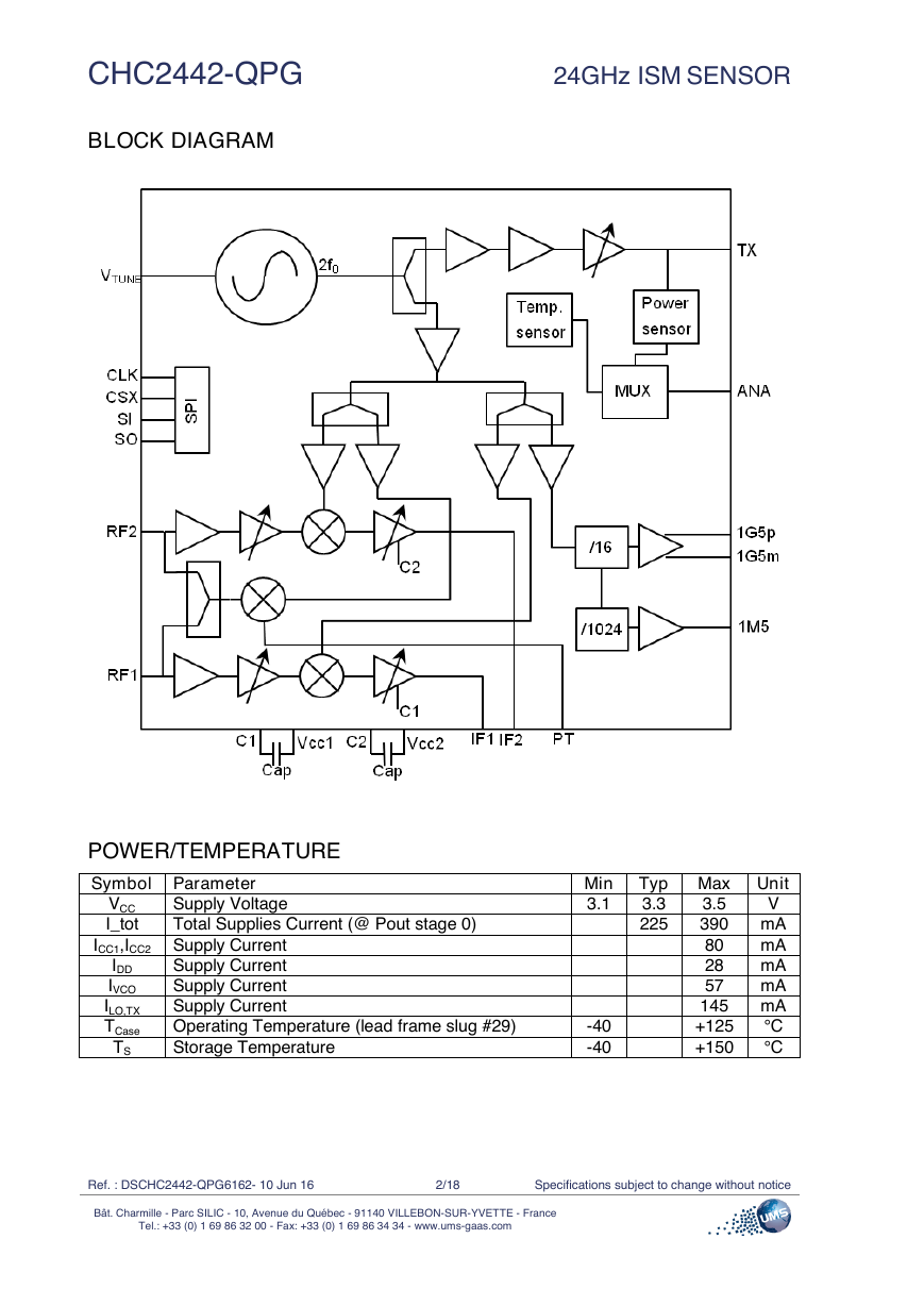
BLOCK DIAGRAM
24GHz ISM SENSOR
POWER/TEMPERATURE
Symbol Parameter
VCC
I_tot
Supply Voltage
Total Supplies Current (@ Pout stage 0)
ICC1,ICC2 Supply Current
Supply Current
Supply Current
Supply Current
Operating Temperature (lead frame slug #29)
Storage Temperature
IDD
IVCO
ILO,TX
TCase
TS
Min Typ Max Unit
3.1
3.3
225
-40
-40
3.5
V
390 mA
mA
80
28
mA
57
mA
145 mA
°C
+125
+150
°C
Ref. : DSCHC2442-QPG6162- 10 Jun 16
2/18
Specifications subject to change without notice
Bât. Charmille - Parc SILIC - 10, Avenue du Québec - 91140 VILLEBON-SUR-YVETTE - France
Tel.: +33 (0) 1 69 86 32 00 - Fax: +33 (0) 1 69 86 34 34 - www.ums-gaas.com
�
24GHz ISM SENSOR
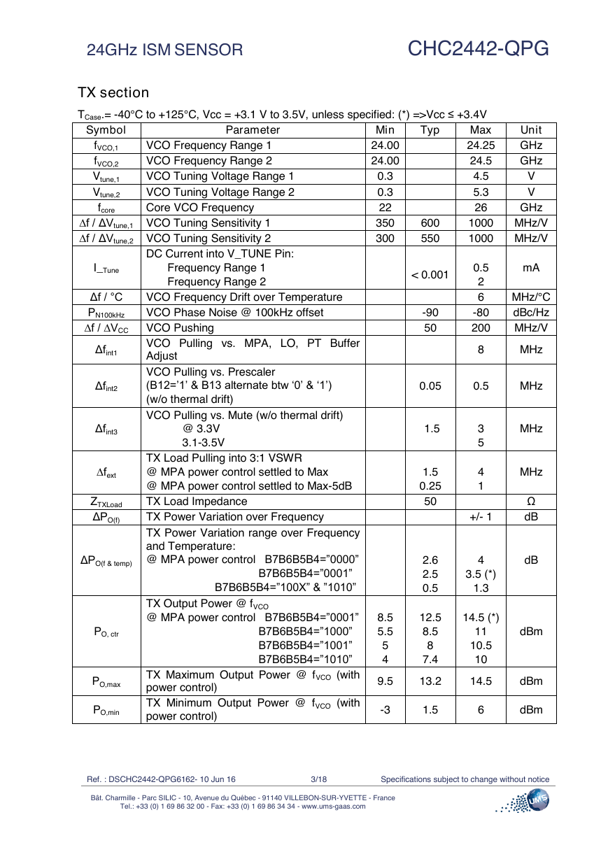
TX section
CHC2442-QPG
Symbol
Parameter
Typ
TCase.= -40°C to +125°C, Vcc = +3.1 V to 3.5V, unless specified: (*) =>Vcc ≤ +3.4V
Max
24.25
24.5
4.5
5.3
26
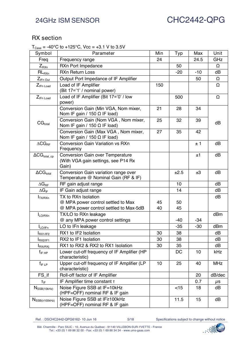
VCO Frequency Range 1
VCO Frequency Range 2
VCO Tuning Voltage Range 1
VCO Tuning Voltage Range 2
Core VCO Frequency
fVCO,1
fVCO,2
Vtune,1
Vtune,2
fcore
Unit
GHz
GHz
V
V
GHz
∆f / ΔVtune,1 VCO Tuning Sensitivity 1
∆f / ΔVtune,2 VCO Tuning Sensitivity 2
DC Current into V_TUNE Pin:
I_Tune
Frequency Range 1
Frequency Range 2
Δf / °C
PN100kHz
∆f / ∆VCC VCO Pushing
VCO Frequency Drift over Temperature
VCO Phase Noise @ 100kHz offset
Δfint1
Δfint2
Δfint3
∆fext
ZTXLoad
ΔPO(f)
ΔPO(f & temp)
PO, ctr
PO,max
PO,min
VCO Pulling vs. MPA, LO, PT Buffer
Adjust
VCO Pulling vs. Prescaler
(B12=’1’ & B13 alternate btw ‘0’ & ‘1’)
(w/o thermal drift)
VCO Pulling vs. Mute (w/o thermal drift)
@ 3.3V
3.1-3.5V
TX Load Pulling into 3:1 VSWR
@ MPA power control settled to Max
@ MPA power control settled to Max-5dB
TX Load Impedance
TX Power Variation over Frequency
TX Power Variation range over Frequency
and Temperature:
@ MPA power control B7B6B5B4=”0000”
B7B6B5B4=”0001”
B7B6B5B4=”100X” & ”1010”
TX Output Power @ fVCO
@ MPA power control B7B6B5B4=”0001”
B7B6B5B4=”1000”
B7B6B5B4=”1001”
B7B6B5B4=”1010”
TX Maximum Output Power @ fVCO (with
power control)
TX Minimum Output Power @ fVCO (with
power control)
Min
24.00
24.00
0.3
0.3
22
350
300
8.5
5.5
5
4
9.5
600
550
< 0.001
-90
50
1000 MHz/V
1000 MHz/V
0.5
2
6
-80
200
mA
MHz/°C
dBc/Hz
MHz/V
8
MHz
0.05
0.5
MHz
1.5
1.5
0.25
50
2.6
2.5
0.5
12.5
8.5
8
7.4
3
5
4
1
+/- 1
4
3.5 (*)
1.3
14.5 (*)
11
10.5
10
MHz
MHz
Ω
dB
dB
dBm
13.2
14.5
dBm
-3
1.5
6
dBm
Ref. : DSCHC2442-QPG6162- 10 Jun 16
3/18
Specifications subject to change without notice
Bât. Charmille - Parc SILIC - 10, Avenue du Québec - 91140 VILLEBON-SUR-YVETTE - France
Tel.: +33 (0) 1 69 86 32 00 - Fax: +33 (0) 1 69 86 34 34 - www.ums-gaas.com
�
CHC2442-QPG
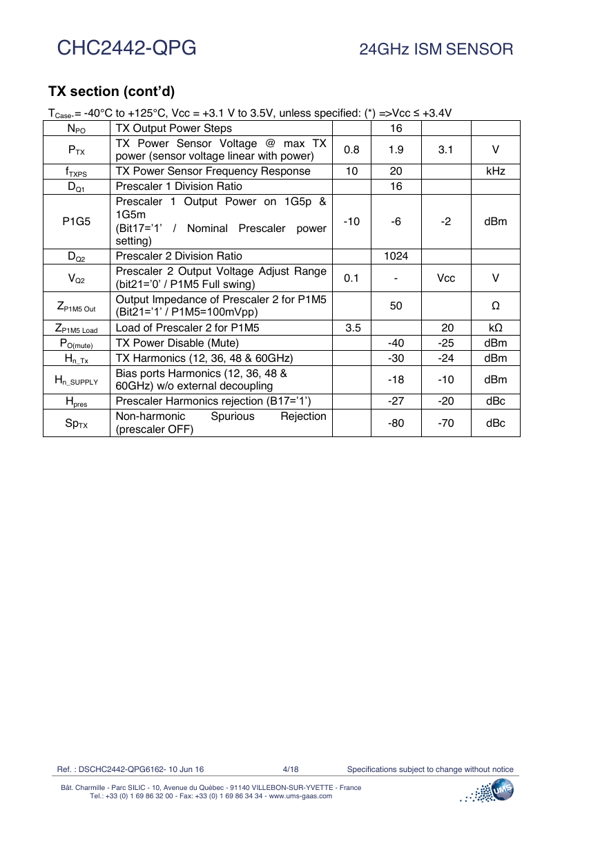
TX section (cont’d)
24GHz ISM SENSOR
TCase.= -40°C to +125°C, Vcc = +3.1 V to 3.5V, unless specified: (*) =>Vcc ≤ +3.4V
16
NPO
/ Nominal Prescaler power
TX Output Power Steps
TX Power Sensor Voltage @ max TX
power (sensor voltage linear with power)
TX Power Sensor Frequency Response
Prescaler 1 Division Ratio
Prescaler 1 Output Power on 1G5p &
1G5m
(Bit17=’1’
setting)
Prescaler 2 Division Ratio
Prescaler 2 Output Voltage Adjust Range
(bit21=’0’ / P1M5 Full swing)
Output Impedance of Prescaler 2 for P1M5
(Bit21=’1’ / P1M5=100mVpp)
Load of Prescaler 2 for P1M5
TX Power Disable (Mute)
TX Harmonics (12, 36, 48 & 60GHz)
Bias ports Harmonics (12, 36, 48 &
60GHz) w/o external decoupling
Prescaler Harmonics rejection (B17=’1’)
Non-harmonic
(prescaler OFF)
Rejection
Spurious
PTX
fTXPS
DQ1
P1G5
DQ2
VQ2
ZP1M5 Out
ZP1M5 Load
PO(mute)
Hn_Tx
Hn_SUPPLY
Hpres
SpTX
0.8
1.9
3.1
10
20
16
V
kHz
-10
-6
-2
dBm
1024
0.1
-
Vcc
3.5
50
-40
-30
-18
-27
-80
20
-25
-24
-10
-20
-70
V
Ω
kΩ
dBm
dBm
dBm
dBc
dBc
Ref. : DSCHC2442-QPG6162- 10 Jun 16
4/18
Specifications subject to change without notice
Bât. Charmille - Parc SILIC - 10, Avenue du Québec - 91140 VILLEBON-SUR-YVETTE - France
Tel.: +33 (0) 1 69 86 32 00 - Fax: +33 (0) 1 69 86 34 34 - www.ums-gaas.com
�
24GHz ISM SENSOR
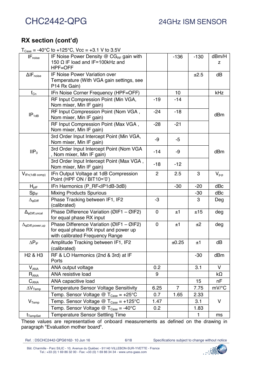
RX section
TCase = -40°C to +125°C, Vcc = +3.1 V to 3.5V
Symbol
Freq
ZRXn
RLRXn
ZIFn Out
ZIFn Load
ZIFn Load
CGtotal
∆CGRF
Parameter
Frequency range
RXn Port Impedance
RXn Return Loss
Output Port Impedance of IF Amplifier
Load of IF Amplifier
(Bit 17=’1’ / nominal power)
Load of IF Amplifier (Bit 17=’0’ / low
power)
Conversion Gain (Min VGA, Nom mixer,
Nom IF gain / 150 Ω IF load)
Conversion Gain (Nom VGA , Nom mixer,
Nom IF gain / 150 Ω IF load)
Conversion Gain (Max VGA , Nom mixer,
Nom IF gain / 150 Ω IF load)
Conversion Gain Variation vs RXn
Frequency
ΔCGtotal_cp Conversion Gain over Temperature
(With VGA gain settings, see P14 Rx
Gain)
Conversion Gain variation range over
Temperature @ Nominal Gain (RF & IF)
RF gain adjust range
IF Gain adjust range
TX to RXn Isolation
@ MPA power control settled to Max
@ MPA power control settled to Max-5dB
TX/LO to RXn leakage
@ any MPA power control settings
LO to IFn leakage
RX1 to IF2 Isolation
RX2 to IF1 Isolation
RX1 to RX2 & RX2 to RX1 Isolation
Lower cut-off frequency of IF Amplifier (HP
characteristic)
Upper cut-off frequency of IF Amplifier (LP
characteristic)
Roll-off factor of IF Amplifier
IF Amplifier time constant τ
ΔCGtotal
∆GRF
∆GIF
ITX/RXn
ILO/RXn
ILO/IFn
IRX1/IF2
IRX2/IF1
IRXi/RXj
fIF HP
fIF LP
FS_if
τIF
NSSB(10kHz) Noise Figure SSB at IF=10kHz
(HPF=OFF) nominal RF & IF gain
NSSB(≥100kHz) Noise Figure SSB at IF≥100kHz
(HPF=OFF) nominal RF & IF gain
CHC2442-QPG
Min
24
150
Typ
50
-20
500
28
32
35
21
25
27
45
40
30
30
30
10
Max
24.5
-10
50
34
39
42
± 1
±1
±2.5
±3
10
14
50
45
-40
-35
38
38
35
DC
25
<15
-34
-30
10
40
20
0.7
18
11.5
15
Unit
GHz
Ω
dB
Ω
Ω
Ω
dB
dB
dB
dB
dB
dB
dB
dBm
dBm
dB
dB
dB
kHz
MHz
dB/dec
µs
dB
dB
Ref. : DSCHC2442-QPG6162- 10 Jun 16
5/18
Specifications subject to change without notice
Bât. Charmille - Parc SILIC - 10, Avenue du Québec - 91140 VILLEBON-SUR-YVETTE - France
Tel.: +33 (0) 1 69 86 32 00 - Fax: +33 (0) 1 69 86 34 34 - www.ums-gaas.com
�
24GHz ISM SENSOR
-136
-130
dBm/H
z
±2.5
dB
-24
-18
-28
-21
CHC2442-QPG
RX section (cont’d)
TCase = -40°C to +125°C, Vcc = +3.1 V to 3.5V
IFnoise
ΔIFnoise
fCn
IP1dB
IIP3
VIFn(1dB comp)
HpIF
SpIF
∆φDiff
ΔφDiff,uncal
IF Noise Power Density @ CGRF gain with
150 Ω IF load and IF=100kHz and
HPF=OFF
IF Noise Power Variation over
Temperature (With VGA gain settings, see
P14 Rx Gain)
IFn Noise Corner Frequency (HPF=OFF)
RF Input Compression Point (Min VGA,
Nom mixer, Min IF gain)
RF Input Compression Point (Nom VGA ,
Nom mixer, Min IF gain)
RF Input Compression Point (Max VGA ,
Nom mixer, Min IF gain)
3rd Order Input Intercept Point (Min VGA,
Nom mixer, Min IF gain)
3rd Order Input Intercept Point (Nom VGA
, Nom mixer, Min IF gain)
3rd Order Input Intercept Point (Max VGA ,
Nom mixer, Min IF gain)
IFn Output Voltage at 1dB Compression
Point (HPF ON / BIT10=’0’)
IFn Harmonics (P_RF
24GHz ISM SENSOR
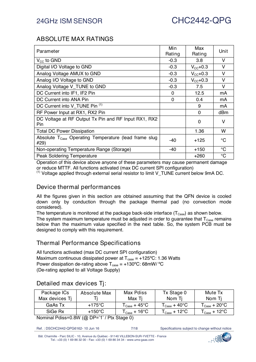
ABSOLUTE MAX RATINGS
Parameter
CHC2442-QPG
Min
Rating
Max
Rating
Unit
3.8
-0.3
-0.3
-0.3
-0.3
-0.3
VCC+0.3
VCC+0.3
VCC+0.3
V
V
V
V
V
mA
mA
mA
dBm
VCC to GND
Digital I/O Voltage to GND
Analog Voltage AMUX to GND
Analog I/O Voltage to GND
Analog Voltage V_TUNE to GND
DC Current into IF1, IF2 Pin
DC Current into ANA Pin
DC Current into V_TUNE Pin (1)
RF Power Input at RX1, RX2 Pin
DC Voltage at RF Output Tx Pin and RF Input RX1, RX2
Pin
Total DC Power Dissipation
Absolute TCase Operating Temperature (lead frame slug
#29)
°C
Non-operating Temperature Range (Storage)
Peak Soldering Temperature
°C
Operation of this device above anyone of these parameters may cause permanent damage
or reduce MTTF. All functions activated (max DC current SPI configuration)
(1) Voltage applied through external serial resistor to limit V_TUNE current below 9mA DC.
Device thermal performances
7.5
12.5
0.4
9
0
0
0
+150
+260
-40
-40
V
W
°C
0
1.36
+125
All the figures given in this section are obtained assuming that the QFN device is cooled
down only by conduction through the package thermal pad (no convection mode
considered).
The temperature is monitored at the package back-side interface (TCase) as shown below.
The system maximum temperature must be adjusted in order to guarantee that TCase remains
below than the maximum value specified in the next table. So, the system PCB must be
designed to comply with this requirement.
Thermal Performance Specifications
All functions activated (max DC current SPI configuration)
Maximum continuous dissipated power at Tcase = +125ºC: 1.36 Watts
Power dissipation de-rating above Tcase = +130ºC: 68mW/ ºC
(De-rating applied to all Voltage Supply)
Detailed max devices Tj:
Package ICs
Absolute Max
Max Pdiss
Max devices Tj
GaAs Tx
SiGe Rx
Tj
+175°C
+150°C
Max Tj
TCase + 45°C
TCase + 16°C
Tx Stage 0
Nom Tj
TCase + 40°C
TCase + 12°C
Mute Tx
Nom Tj
TCase + 20°C
TCase + 12°C
Nominal Pdiss=0.8W (@ DP=’1’ / Ptx Stage 0)
Ref. : DSCHC2442-QPG6162- 10 Jun 16
7/18
Specifications subject to change without notice
Bât. Charmille - Parc SILIC - 10, Avenue du Québec - 91140 VILLEBON-SUR-YVETTE - France
Tel.: +33 (0) 1 69 86 32 00 - Fax: +33 (0) 1 69 86 34 34 - www.ums-gaas.com
�
CHC2442-QPG
24GHz ISM SENSOR
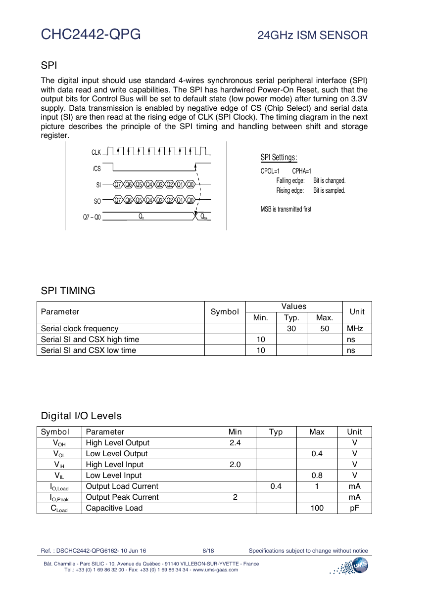
SPI
The digital input should use standard 4-wires synchronous serial peripheral interface (SPI)
with data read and write capabilities. The SPI has hardwired Power-On Reset, such that the
output bits for Control Bus will be set to default state (low power mode) after turning on 3.3V
supply. Data transmission is enabled by negative edge of CS (Chip Select) and serial data
input (SI) are then read at the rising edge of CLK (SPI Clock). The timing diagram in the next
picture describes the principle of the SPI timing and handling between shift and storage
register.
SPI TIMING
Parameter
Serial clock frequency
Serial SI and CSX high time
Serial SI and CSX low time
Digital I/O Levels
Symbol
VOH
VOL
VIH
VIL
IO,Load
IO,Peak
CLoad
Parameter
High Level Output
Low Level Output
High Level Input
Low Level Input
Output Load Current
Output Peak Current
Capacitive Load
Symbol
Values
Typ.
30
Max.
50
Unit
MHz
ns
ns
Min.
10
10
Min
2.4
2.0
2
Typ
Max
Unit
0.4
0.4
0.8
1
100
V
V
V
V
mA
mA
pF
Ref. : DSCHC2442-QPG6162- 10 Jun 16
8/18
Specifications subject to change without notice
Bât. Charmille - Parc SILIC - 10, Avenue du Québec - 91140 VILLEBON-SUR-YVETTE - France
Tel.: +33 (0) 1 69 86 32 00 - Fax: +33 (0) 1 69 86 34 34 - www.ums-gaas.com
SPI Settings: CPOL=1 CPHA=1 Falling edge: Bit is changed. Rising edge: Bit is sampled. MSB is transmitted first CLK /CS SI SO Q7 – Q0 Q7 Q6 Q5 Q4 Q3 Q2 Q1 Q0 Q7 Q6 Q5 Q4 Q3 Q2 Q1 Q0 Qn Qn+1 �


 2023年江西萍乡中考道德与法治真题及答案.doc
 2012年重庆南川中考生物真题及答案.doc
 2013年江西师范大学地理学综合及文艺理论基础考研真题.doc
 2020年四川甘孜小升初语文真题及答案I卷.doc
 2020年注册岩土工程师专业基础考试真题及答案.doc
 2023-2024学年福建省厦门市九年级上学期数学月考试题及答案.doc
 2021-2022学年辽宁省沈阳市大东区九年级上学期语文期末试题及答案.doc
 2022-2023学年北京东城区初三第一学期物理期末试卷及答案.doc
 2018上半年江西教师资格初中地理学科知识与教学能力真题及答案.doc
 2012年河北国家公务员申论考试真题及答案-省级.doc
 2020-2021学年江苏省扬州市江都区邵樊片九年级上学期数学第一次质量检测试题及答案.doc
 2022下半年黑龙江教师资格证中学综合素质真题及答案.doc