logo资料库

Axp288电源管理.pdf

第1页 / 共102页
第2页 / 共102页
第3页 / 共102页
第4页 / 共102页
第5页 / 共102页
第6页 / 共102页
第7页 / 共102页
第8页 / 共102页
资料共102页,剩余部分请下载后查看
Revision History
Declaration
Catalog
1 Overview
2 Feature
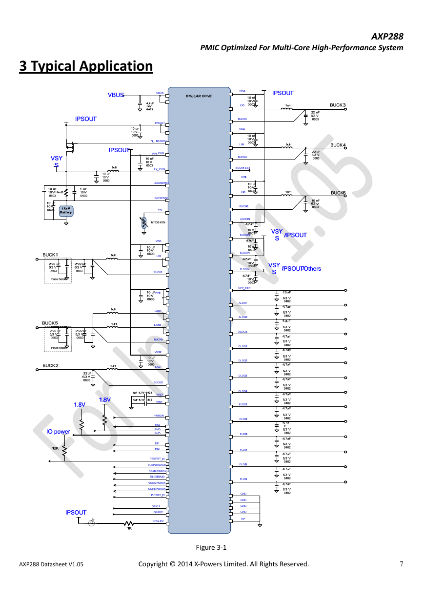
3 Typical Application
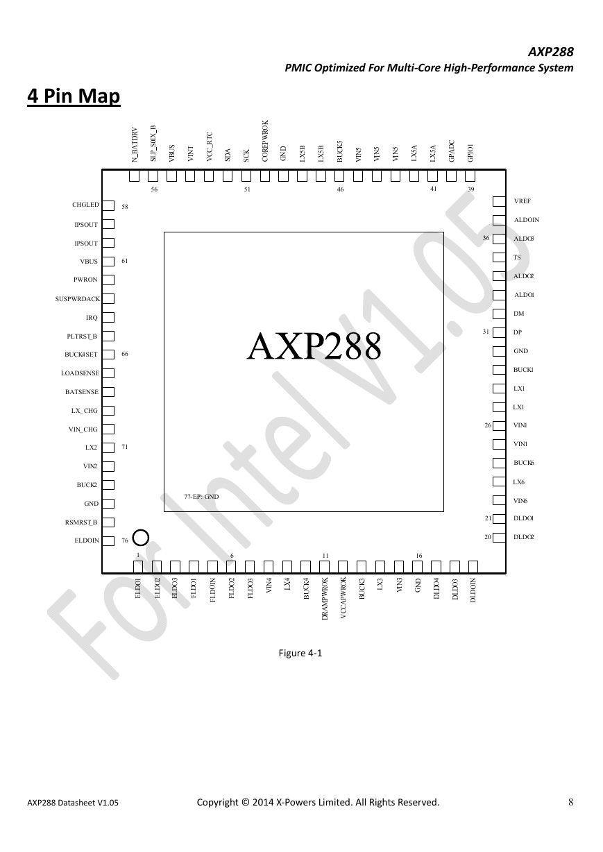
4 Pin Map
5 Pin Description
6 Block Diagram
7 Absolute Maximum Ratings
8 Electrical Characteristics
9 Control and operation
9.1 Power on/off and Power sequences
9.1.1 Power on/off sources
9.1.2 Power up sequence
9.1.3 Power down Sequencing
9.1.4 Cold Reset and Global reset
9.1.5 Sleep state control
9.2 IPS (Intelligent Power Select)
9.2.1 IPS overview
9.2.2 IPSOUT source selection
9.2.3 VBUS current/voltage limitation
9.2.4 VBUS input overvoltage protection
9.2.5 VBUS insertion power up condition
9.3 BC Detection Module
9.4 Adaptive PWM Charger
9.4.1 Charger Overview
9.4.2 Charging start and stop
9.4.3 Timeout activity
9.4.4 CHGLED activity
9.4.5 Battery detection
9.4.6 Temperature protection
9.5 Multi-Power Outputs
9.6 ADC
9.7 Fuel Gauge
9.8 Interrupt Controller
9.9 TWSI
10 Register
Register List
REG 00H: Power source status
REG 01H: Power mode and Charger status
REG 02H: Power up/down reason register
REG 03H: IC type no.
REG 04-0FH: 12 Data buffers
REG 10H: Output power on-off control 1
REG 12H: Output power on-off control 2
REG 13H: Output power on-off control 3
REG 14H: On/Off synchronous control
REG 15H: DLDO1 voltage control
REG 16H: DLDO2 voltage control
REG 17H: DLDO3 voltage control
REG 18H: DLDO4 voltage control
REG 19H: ELDO1 voltage control
REG 1AH: ELDO2 voltage control
REG 1BH: ELDO3 voltage control
REG 1CH: FLDO1 voltage control
REG 1DH: FLDO2/3 voltage control
REG 20H: BUCK6 voltage control
REG 21H: BUCK5 voltage control
REG 22H: Reserved
REG 23H: BUCK1 voltage control
REG 24H: BUCK4 voltage control
REG 25H: BUCK3 voltage control
REG 26H: BUCK2 voltage control
REG 27H: BUCK1 /2 /3 /4 /5 DVM control
REG 28H: ALDO1 voltage control
REG 29H: ALDO2 voltage control
REG 2AH: ALDO3 voltage control
REG 2CH: BC Module Global Register
REG 2DH: BC Module VBUS Control and Status Register
REG 2EH: BC USB Status Register
REG 2FH: BC Detect Status Register
REG 30H: VBUS path control & Hold voltage setting
REG 31H: Power wakeup control & VOFF setting
REG 32H: Power Disable, BAT detect and CHGLED pin control
REG 33H: Charger Control 1
REG 34H: Charger Control 2
REG 35H: Charger Control 3
REG 36H: POK setting
REG 37H: POK Power off activity time setting
REG 38H: VLTF-charge setting
REG 39H: VHTF-charge setting
REG 3AH: Reserved
REG 3BH: Buck frequency setting
REG 3CH: VLTF-work setting
REG 3DH: VHTF-work setting
REG 40H: IRQ enable 1
REG 41H: IRQ enable 2
REG 42H: IRQ enable 3
REG 43H: IRQ enable 4
REG 44H: IRQ enable 5
REG 45H: IRQ enable 6
REG 48H: IRQ Status 1
REG 49H: IRQ Status 2
REG 4AH: IRQ Status 3
REG 4BH: IRQ Status 4
REG 4CH: IRQ Status 5
REG 4DH: IRQ Status 6
REG 58H: TS pin input ADC data, highest 8bit
REG 59H: TS pin input ADC data, lowest 4bit
REG 5AH: GPADC pin input ADC data, highest 8bit
REG 5BH: GPADC pin input ADC data, lowest 4bit
REG 78H: Average data bit[11:4] for Battery voltage (BATSENSE)
REG 79H: Average data bit[3:0] for Battery voltage (BATSENSE)
REG 7AH: Average data bit[11:4] for Battery charge current
REG 7BH: Average data bit[3:0] for Battery charge current
REG 7CH: Average data bit[11:4] for Battery discharge current
REG 7DH: Average data bit[3:0] for Battery discharge current
REG 80H: Buck PWM/PFM mode select
REG 81H: Off-Discharge and Output monitor control
REG 82H: ADC Enable
REG 84H: ADC speed setting, TS pin Control
REG 85H: ADC speed setting
REG 8AH: Timer control
REG 8EH: Buck output voltage monitor de-bounce time setting
REG 8FH: IRQ pin, hot-over shut down
REG 90H: GPIO0 (GPADC) control
REG 91H: GPIO0LDO and GPIO0 high level voltage setting
REG 92H: GPIO1 control
REG 93H: GPIO1LDO and GPIO1 high level voltage setting
REG 94H: GPIO signal bit
REG 97H: GPIO pull down control
REG 9AH: Run time Sleep power up sequence 1
REG 9BH: Run time Sleep power up sequence 2
REG 9CH: Run time Sleep power down sequence 1
REG 9DH: Run time Sleep power down sequence 2
REG 9EH: Power rail mode in Sleep state
REG B8H: Fuel Gauge Control
REG B9H: Battery capacity percentage for indication
REG BAH: RDC 1
REG BBH: RDC 0
REG BCH: OCV 1
REG BDH: OCV0
REG E0H: Battery maximum capacity
REG E1H: Battery maximum capacity
REG E2H: Coulomb meter counter1
REG E3H: Coulomb meter counter2
REG E4H: OCV Percentage of battery capacity
REG E5H: Coulomb meter percentage of battery capacity
REG E6H: Battery capacity percentage warning level
REG E8H: Fuel gauge tuning control 0
REG E9H: Fuel gauge tuning control 1
REG EAH: Fuel gauge tuning control 2
REG EBH: Fuel gauge tuning control 3
REG ECH: Fuel gauge tuning control 4
REG EDH: Fuel gauge tuning control 5
11 Package
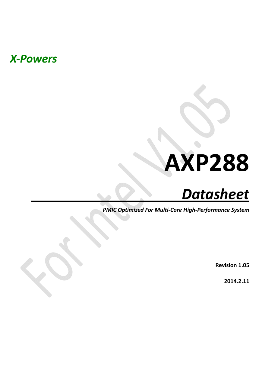
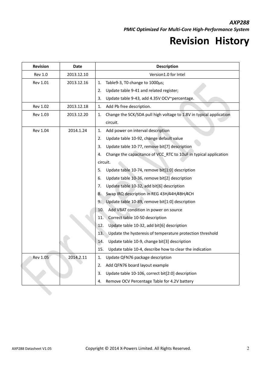
X‐Powers                                AXP288                                        Datasheet  PMIC Optimized For Multi‐Core High‐Performance System              Revision 1.05    2014.2.11                   
                                                                              AXP288  PMIC Optimized For Multi‐Core High‐Performance System       Revision  History  Description  Version1.0 for Intel  0μs;  1. Table9‐3, T0 change to 100 2. Update table 9‐41 and  3. Update table 9‐43, add 4.35V OC 1.   Add  Pb free description.  1. Change the SCK/SDA pull high voltage to 1.8V in  related register;  V~percentage.  typical application  circuit.  scription  ate table 10‐36, remove bit[2] description  1.   Add  power on interval description  2.   Update  table 10‐92, change default value  3.   Upda te table 10‐77, remove bit[7] de 4.   Change  the capacitance of VCC_RTC to 10u circuit.  5.   Update  table 10‐74, remove bit[1:0] description  6.   Upd 7.   Upda te table 10‐32, add bit[6] description  8.   Swap  IRQ description in REG 43H/44H/4BH/4CH   9.   Update  table 10‐89, remove bit[1:0] descrip tion  10.   Add  VBAT condition in power on source  11.   Correct  table 10‐50 description  12.   Update  table 10‐32, add bit[6] descriptio 13.   Update  the hysteresis of temper 14.   Update  table 10‐9, change bit[3] description 15.   Update  table 10‐4, describe how to clear the indication  1. Update QFN76 package description  2. Add QFN76 board layout example  3. Update table 10‐106, correct bit[2:0] 4. Remove OCV Percentage Table for 4.2V  description   battery  ature protection threshold  F in typical application  n    Revision  Rev 1.0  Rev 1.01  Date  2013.12.10  20 13.12.16   Rev 1.02  Rev 1.03  2013.12.18  2013.12.2 0  Rev 1.04  2014.1.24  Rev 1.05  2014.2.11          AXP288 Datasheet V1.05                          Copyright © 2014 X‐Powers Limited. All Rights Reserved.  2
                                                                                AXP288  PMIC Optimized For Multi‐Core High‐Performance System       Declaration    X‐Powers cannot assume responsibility for use of any circuitry other than circuitry entirely embodied in an X‐Powers product.  No  circuit  patent  licenses, copyrights,  or  other  intellectual  property  rights  are  implied.  X‐Powers  reserves  the  right  to make  changes to the specifications and products at any time without notice.    AXP288 Datasheet V1.05                          Copyright © 2014 X‐Powers Limited. All Rights Reserved.  3
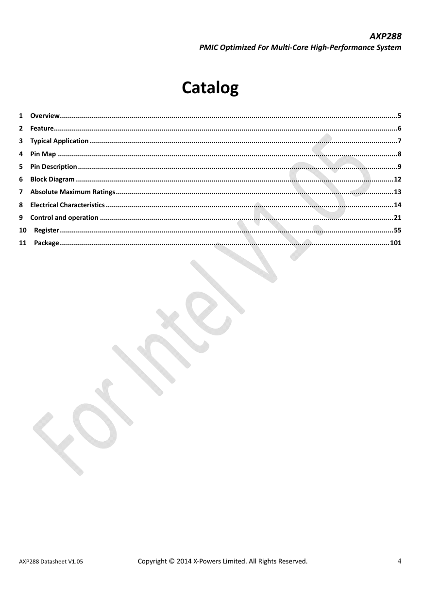
                                                                                AXP288  PMIC Optimized For Multi‐Core High‐Performance System       Catalog  1   Overview.........................................................................................................................................................................5   2   Feature............................................................................................................................................................................6   3   Typical  Application ..........................................................................................................................................................7  4   Pin  Map ..........................................................................................................................................................................8  5   Pin  Description................................................................................................................................................................9  6   Block  Diagram ...............................................................................................................................................................12  7   Absolute  Maximum Ratings...........................................................................................................................................13  8   Electrical  Characteristics ................................................................................................................................................14  9   Control  and operation ...................................................................................................................................................21  10   Register....................................................................................................................... ................................................55  11   Package........................................................................................................................ .............................................101                                                AXP288 Datasheet V1.05                          Copyright © 2014 X‐Powers Limited. All Rights Reserved.  4
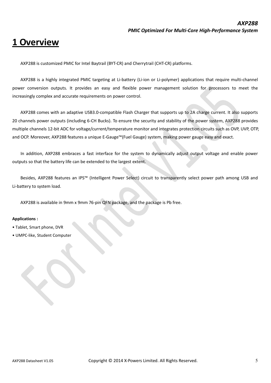
                                                                              AXP288  PMIC Optimized For Multi‐Core High‐Performance System       1 Overview    AXP288 is customized PMIC for Intel Baytrail (BYT‐CR) and Cherrytrail (CHT‐CR) platforms.    AXP288  is  a  highly  integrated  PMIC  targeting  at  Li‐battery  (Li‐ion  or  Li‐polymer)  applications  that  require  multi‐channel  power  conversion  outputs.  It  provides  an  easy  and  flexible  power  management  solution  for  processors  to  meet  the  increasingly complex and accurate requirements on power control.    AXP288 comes with an adaptive USB3.0‐compatible Flash Charger that supports up to 2A charge current. It also supports  20 channels power outputs (including 6‐CH Bucks). To ensure the security and stability of the power system, AXP288 provides  multiple channels 12‐bit ADC for voltage/current/temperature monitor and integrates protection circuits such as OVP, UVP, OTP,  and OCP. Moreover, AXP288 features a unique E‐Gauge™(Fuel Gauge) system, making power gauge easy and exact.      In  addition,  AXP288  embraces  a  fast  interface  for  the  system  to  dynamically  adjust  output  voltage  and  enable  power  outputs so that the battery life can be extended to the largest extent.      Besides,  AXP288  features  an  IPS™  (Intelligent  Power  Select)  circuit  to  transparently  select  power  path  among  USB  and  Li‐battery to system load.    AXP288 is available in 9mm x 9mm 76‐pin QFN package, and the package is Pb free.      Applications :  • Tablet, Smart phone, DVR    • UMPC‐like, Student Computer                              AXP288 Datasheet V1.05                          Copyright © 2014 X‐Powers Limited. All Rights Reserved.  5
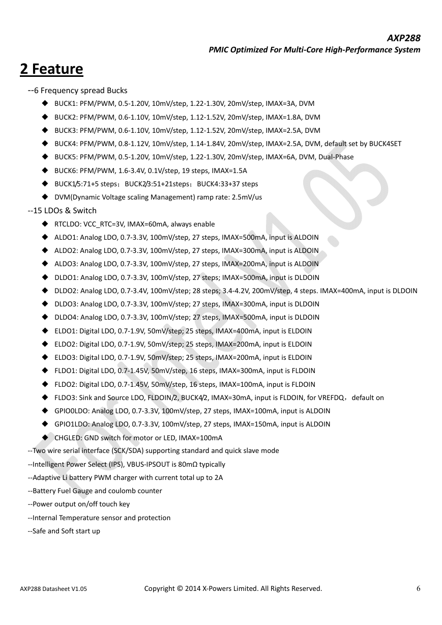
                                                                              AXP288  PMIC Optimized For Multi‐Core High‐Performance System       2 Feature  ‐‐6 Frequency spread Bucks  ◆ BUCK1: PFM/PWM, 0.5‐1.20V, 10mV/step, 1.22‐1.30V, 20mV/step, IMAX=3A, DVM  ◆ BUCK2: PFM/PWM, 0.6‐1.10V, 10mV/step, 1.12‐1.52V, 20mV/step, IMAX=1.8A, DVM  ◆ BUCK3: PFM/PWM, 0.6‐1.10V, 10mV/step, 1.12‐1.52V, 20mV/step, IMAX=2.5A, DVM  ◆ BUCK4: PFM/PWM, 0.8‐1.12V, 10mV/step, 1.14‐1.84V, 20mV/step, IMAX=2.5A, DVM, default set by BUCK4SET  ◆ BUCK5: PFM/PWM, 0.5‐1.20V, 10mV/step, 1.22‐1.30V, 20mV/step, IMAX=6A, DVM, Dual‐Phase  ◆ BUCK6: PFM/PWM, 1.6‐3.4V, 0.1V/step, 19 steps, IMAX=1.5A  ◆ BUCK1/5:71+5 steps;BUCK2/3:51+21steps;BUCK4:33+37 steps  ◆ DVM(Dynamic Voltage scaling Management) ramp rate: 2.5mV/us  ‐‐15 LDOs & Switch  ◆ RTCLDO: VCC_RTC=3V, IMAX=60mA, always enable  ◆ ALDO1: Analog LDO, 0.7‐3.3V, 100mV/step, 27 steps, IMAX=500mA, input is ALDOIN  ◆ ALDO2: Analog LDO, 0.7‐3.3V, 100mV/step, 27 steps, IMAX=300mA, input is ALDOIN  ◆ ALDO3: Analog LDO, 0.7‐3.3V, 100mV/step, 27 steps, IMAX=200mA, input is ALDOIN  ◆ DLDO1: Analog LDO, 0.7‐3.3V, 100mV/step, 27 steps; IMAX=500mA, input is DLDOIN  ◆ DLDO2: Analog LDO, 0.7‐3.4V, 100mV/step; 28 steps; 3.4‐4.2V, 200mV/step, 4 steps. IMAX=400mA, input is DLDOIN  ◆ DLDO3: Analog LDO, 0.7‐3.3V, 100mV/step; 27 steps, IMAX=300mA, input is DLDOIN  ◆ DLDO4: Analog LDO, 0.7‐3.3V, 100mV/step; 27 steps, IMAX=500mA, input is DLDOIN  ◆ ELDO1: Digital LDO, 0.7‐1.9V, 50mV/step; 25 steps, IMAX=400mA, input is ELDOIN  ◆ ELDO2: Digital LDO, 0.7‐1.9V, 50mV/step; 25 steps, IMAX=200mA, input is ELDOIN  ◆ ELDO3: Digital LDO, 0.7‐1.9V, 50mV/step; 25 steps, IMAX=200mA, input is ELDOIN  ◆ FLDO1: Digital LDO, 0.7‐1.45V, 50mV/step, 16 steps, IMAX=300mA, input is FLDOIN  ◆ FLDO2: Digital LDO, 0.7‐1.45V, 50mV/step, 16 steps, IMAX=100mA, input is FLDOIN  ◆ FLDO3: Sink and Source LDO, FLDOIN/2, BUCK4/2, IMAX=30mA, input is FLDOIN, for VREFDQ,default on  ◆ GPIO0LDO: Analog LDO, 0.7‐3.3V, 100mV/step, 27 steps, IMAX=100mA, input is ALDOIN  ◆ GPIO1LDO: Analog LDO, 0.7‐3.3V, 100mV/step, 27 steps, IMAX=150mA, input is ALDOIN  ◆ CHGLED: GND switch for motor or LED, IMAX=100mA  ‐‐Two wire serial interface (SCK/SDA) supporting standard and quick slave mode  ‐‐Intelligent Power Select (IPS), VBUS‐IPSOUT is 80mΩ typically  ‐‐Adaptive Li battery PWM charger with current total up to 2A  ‐‐Battery Fuel Gauge and coulomb counter  ‐‐Power output on/off touch key  ‐‐Internal Temperature sensor and protection  ‐‐Safe and Soft start up    AXP288 Datasheet V1.05                          Copyright © 2014 X‐Powers Limited. All Rights Reserved.  6
3 Typical Application                                                                                AXP288  PMIC Optimized For Multi‐Core High‐Performance System       AXP288 Datasheet V1.05                          Copyright © 2014 X‐Powers Limited. All Rights Reserved.  7 Figure 3‐1  
                                                                              AXP288  PMIC Optimized For Multi‐Core High‐Performance System       56 51 46 41 39 VREF ALDOIN 36 ALDO3 31 26 21 20 TS ALDO2 ALDO1 DM DP GND BUCK1 LX1 LX1 VIN1 VIN1 BUCK6 LX6 VIN6 DLDO1 DLDO2   77-EP: GND 1 6 11 16   Figure 4‐1  4 Pin Map  CHGLED 58 IPSOUT IPSOUT VBUS 61 PWRON SUSPWRDACK IRQ PLTRST_B BUCK4SET 66 LOADSENSE BATSENSE LX_CHG VIN_CHG LX2 VIN2 BUCK2 GND 71 RSMRST_B ELDOIN 76           AXP288 Datasheet V1.05                          Copyright © 2014 X‐Powers Limited. All Rights Reserved.  8
分享到:
收藏