CS/EE 5720/6720 – Analog IC Design
Tutorial for Schematic Design and Analysis using Spectre
Introduction to Cadence EDA:
The Cadence toolset is a complete microchip EDA (Electronic Design Automation)
system, which is intended to develop professional, full-scale, mixed-signal microchips.
The modules included in the toolset are for schematic entry, design simulation, data
analysis, physical layout, and final verification. The Cadence tools at our university are
the same as those at most every professional mixed-signal microelectronics company in
the United States. The strength of
its analog
design/simulation/layout and mixed-signal verification and is often used in tandem with
other tools for digital design/simulation/layout, where complete top-level verification is
done in the Cadence tools.
the Cadence
tools
is
in
An important concept is that the Cadence tools only provide a framework for doing
design. Without a foundry-provided design kit, no design can be done. The design rules
used by Cadence set up in this class is based for AMI’s C5N process (0.5 micron 3 metal
2 poly process).
So, how is Cadence set up?
Broadly, there are three sets of files that need to be in place in order to use Cadence.
1) The Cadence tools
These are the design tools provided by the Cadence company. These tools are
located in the /home/cadence directory. They are capable of VLSI integration,
project management, circuit simulation, design rule verification, and many other
things (most of which we won't use).
2) The foundry-based design kit
As mentioned before, the Cadence tools have to be supported by a foundry-based
design kit. In this class, we use Cadence design kit developed by the North
Carolina State University (NCSU CDK). NCSU CDK provides an environment
that has been customized with several technology files and a fair amount of
custom SKILL code. These files contain information useful for analog/full-
custom digital CMOS IC design via the MOSIS IC fabrication service
(http://www.mosis.org). This information includes layer definitions (e.g. colors,
patterns, etc.), parasitic capacitances, layout cells, SPICE simulation parameters,
Diva rules for Design Rule Check (DRC), extraction, and Layout Versus
Schematic (LVS) verification, with various GUI enhancements.
For more information on the capability of the NCSU CDK, go to
http://www.cadence.ncsu.edu/CDKoverview.html
1
�
This design kit is located in the /home/cadence/ncsu/local directory. All the
design parameters that are needed by the Cadence tools are located in various files
in the sub-directories you will find here. The nominal spice parameters for n type
transistors for AMI’s 0.5 micron process used in this class can be found in
/home/cadence/ncsu/local/models/spectre/nom/ami06N.m.
3) The set up files in your local cadence directory
There are set up files that should be in your local Cadence directory (i.e. the
directory from which you invoke Cadence) that sets up the required local
environmental variables for Cadence to work on your computer terminal. They
are as follows:
.cdsinit, .cdsplotinit, .simrc (sets up the variables to be used by NCSU CDK)
.cdsenv (not essential, but sets your preferences which can be different from user
to user)
Also we need a .cshrc file to source the current version of cadence we are using in
this class.
Now, of the three sets of files, the first two sets containing the cadence tools and the
NCSU CDK have been already set up by the Cadence Administrators for the class. In this
tutorial, the process of setting up the required files in your local cadence directory is
explained.
Setting up Cadence2000
Note: People who have already set up Cadence before still need to follow the steps
below.
Before you start using cadence you need to complete the following steps:
1. First, before anything else, make a directory from which to run Cadence. This is
important so that all of Cadence’s files end up in a consistent location. I
recommend making an IC_CAD directory and then under that making a cadence
directory:
cd
mkdir IC_CAD
mkdir IC_CAD/cadence
2. You need to add the following lines in your .tcshrc file (or whatever shell setup
file you use…) Just open it up with emacs and add:
set path = (/uusoc/facility/cad_common/local/bin $path)
setenv ICDIR IC_CAD
setenv CADENCEDIR $ICDIR/cadence
2
�
setenv LOCAL_CADSETUP /uusoc/facility/cad_common/local/class/5830/cadence
Adding the first line will update your search path to include the path of the
customized CAD tool startup scripts. The next lines set your working directory
for cadence as ‘IC_CAD/cadence’. The fourth line sets up the path to a directory
that contains class-specific settings. After you save this file you can log out and
log in again, or you can source it from the command prompt in the following way.
The sourcing only needs to be done the first time. After that the .tcshrc file will be
sourced automatically when you log in and start up a shell.
:~> source .tcshrc
3
�
Starting Cadence 2000 and Making a new Working Library
Now that you have your own Cadence directory (called IC_CAD/cadence if you’ve
followed the directions up to this point), you need to remember to connect to this
directory before you start the Cadence tools. That way Cadence will see the init files that
you’ve put in that directory, and find the circuits you’ve designed since all the design
files will be stored in this directory. In order to organize your new circuits, you now need
to create a new library using the Cadence library manager to hold your design files.
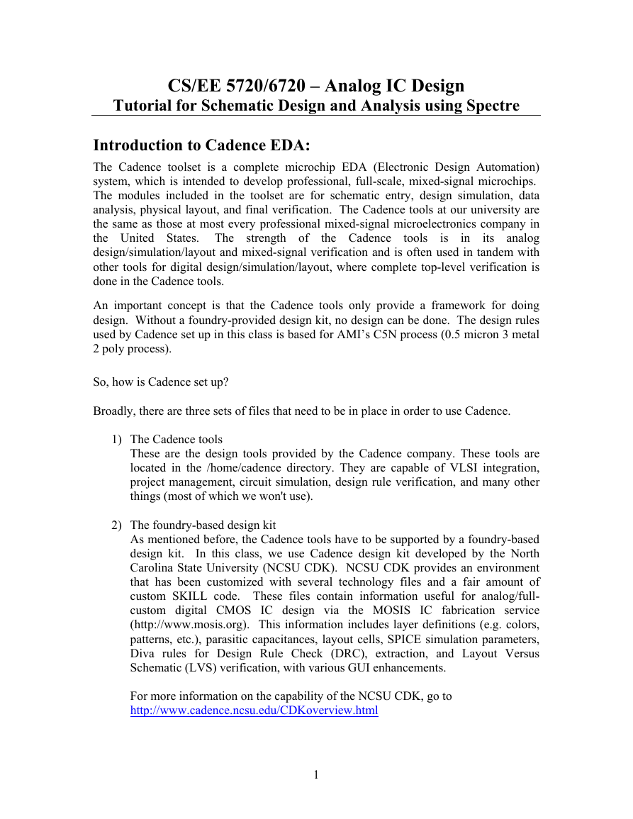
1. Connect to your class cadence directory (cd ~/IC_CAD/cadence) and run the
command ncsu-icfb (this stands for North Carolina State University and “ic front to
back,” in case you’re curious). You should get a window (called the Command
Information Window – CIW) as shown below:
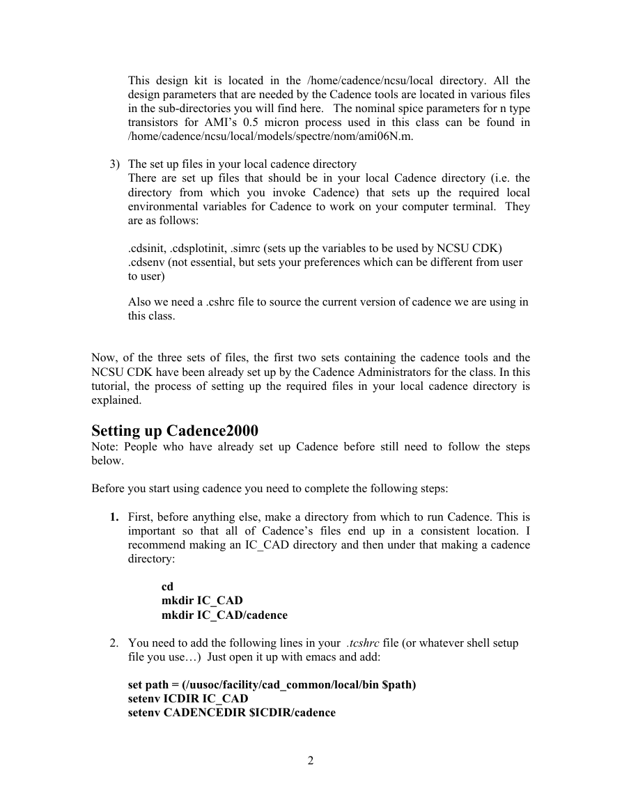
2. Library Manager will automatically be opened. If not, in the CIW, select Tools →
Library Manager…. You should get the following window, with the following list of
libraries:
4
�
3. In order to build your own schematics, you’ll need to define your own library to keep
your own circuits in. To create a new working library in the library manager, select File
→ New → Library. In the Create Library window that appears fill in the Name field as
CSEE5720 (or whatever you’d like to call your library). Select ‘Attach to existing tech
library’ for Technology Library. Select “UofU AMI 0.6u C5N” process and press OK.
Path field is left blank.
5
�
NOTE: This may take a few minutes to execute
Now the working library has been created. All the project cells (components) that you
generate should end up in this library. When you start up the Library Manager to begin
working on your circuits, make sure you select your own library to work in.
Creating a New Cell
When you create a new cell (component in the library), you actually create a view of the
cell. For now we’ll be creating “schematic” views, but eventually you’ll have other
different views of the same cell. For example, a “layout” view of the same cell will have
the composite layout information in it. It’s a different file, but it should represent the
same circuit. This will be discussed later in more details. For now, we’re creating a
schematic view. To create a cell view, carry out the following steps:
Creating the Schematic View of an RC filter
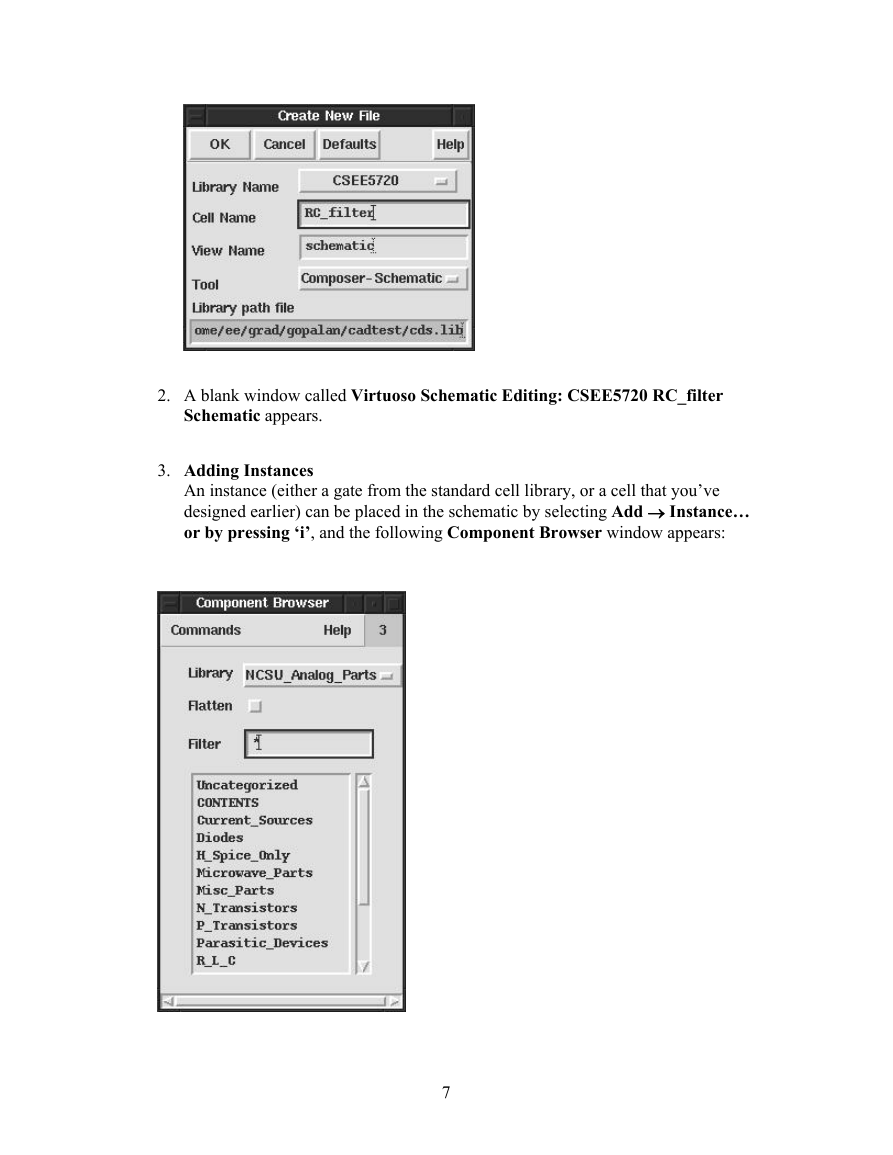
1. Select File → New → Cell View… from the Library Manager menu or to
the CIW menu. The Create New File window appears. The Library Name
field is CSEE5720. Fill in the Cell Name field as RC_filter. Choose
Composer - Schematic from the Tool list and the view name is automatically
filled as Schematic. The library path file is automatically set. Click OK.
6
�
2. A blank window called Virtuoso Schematic Editing: CSEE5720 RC_filter
Schematic appears.
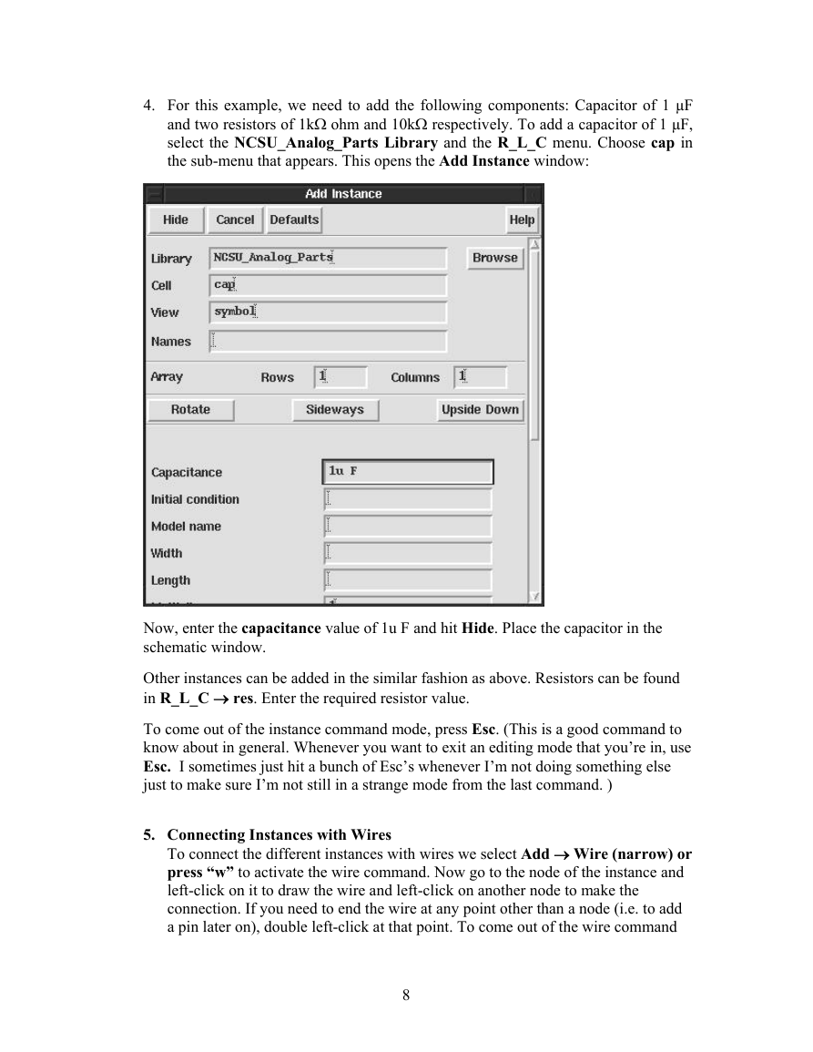
3. Adding Instances
An instance (either a gate from the standard cell library, or a cell that you’ve
designed earlier) can be placed in the schematic by selecting Add → Instance…
or by pressing ‘i’, and the following Component Browser window appears:
7
�
4. For this example, we need to add the following components: Capacitor of 1 µF
and two resistors of 1kΩ ohm and 10kΩ respectively. To add a capacitor of 1 µF,
select the NCSU_Analog_Parts Library and the R_L_C menu. Choose cap in
the sub-menu that appears. This opens the Add Instance window:
Now, enter the capacitance value of 1u F and hit Hide. Place the capacitor in the
schematic window.
Other instances can be added in the similar fashion as above. Resistors can be found
in R_L_C → res. Enter the required resistor value.
To come out of the instance command mode, press Esc. (This is a good command to
know about in general. Whenever you want to exit an editing mode that you’re in, use
Esc. I sometimes just hit a bunch of Esc’s whenever I’m not doing something else
just to make sure I’m not still in a strange mode from the last command. )
5. Connecting Instances with Wires
To connect the different instances with wires we select Add → Wire (narrow) or
press “w” to activate the wire command. Now go to the node of the instance and
left-click on it to draw the wire and left-click on another node to make the
connection. If you need to end the wire at any point other than a node (i.e. to add
a pin later on), double left-click at that point. To come out of the wire command
8
�




 2023年江西萍乡中考道德与法治真题及答案.doc
 2012年重庆南川中考生物真题及答案.doc
 2013年江西师范大学地理学综合及文艺理论基础考研真题.doc
 2020年四川甘孜小升初语文真题及答案I卷.doc
 2020年注册岩土工程师专业基础考试真题及答案.doc
 2023-2024学年福建省厦门市九年级上学期数学月考试题及答案.doc
 2021-2022学年辽宁省沈阳市大东区九年级上学期语文期末试题及答案.doc
 2022-2023学年北京东城区初三第一学期物理期末试卷及答案.doc
 2018上半年江西教师资格初中地理学科知识与教学能力真题及答案.doc
 2012年河北国家公务员申论考试真题及答案-省级.doc
 2020-2021学年江苏省扬州市江都区邵樊片九年级上学期数学第一次质量检测试题及答案.doc
 2022下半年黑龙江教师资格证中学综合素质真题及答案.doc