2
Digital Backward Propagation:
A Technique to Compensate Fiber Dispersion
and Non-Linear Impairments
Rameez Asif, Chien-Yu Lin and Bernhard Schmauss
Chair of Microwave Engineering and High Frequency Technology (LHFT),
Erlangen Graduate School in Advanced Optical Technologies (SAOT),
Friedrich-Alexander University of Erlangen-Nuremberg (FAU),
Cauerstr. 9, (91058) Erlangen
Germany
1. Introduction
Recent numerical and experimental studies have shown that coherent optical QPSK
(CO-QPSK) is the promising candidate for next-generation 100Gbit/s Ethernet (100 GbE)
(Fludger et al., 2008). Coherent detection is considered efficient along with digital signal
processing (DSP) to compensate many linear effects in fiber propagation i.e.
chromatic
dispersion (CD) and polarization-mode dispersion (PMD) and also offers low required optical
signal-to-noise ratio (OSNR). Despite of fiber dispersion and non-linearities which are the
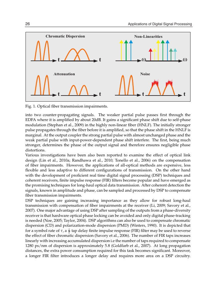
major limiting factors, as illustrated in Fig. 1, optical transmission systems are employing
higher order modulation formats in order to increase the spectral efficiency and thus fulfil
the ever increasing demand of capacity requirements (Mitra et al., 2001). As a result of
which compensation of dispersion and non-linearities (NL), i.e. self-phase modulation (SPM),
cross-phase modulation (XPM) and four-wave mixing (FWM), is a point of high interest these
days.
Various methods of compensating fiber transmission impairments have been proposed in
recent era by implementing all-optical signal processing.
It is demonstrated that the fiber
dispersion can be compensated by using the mid-link spectral inversion method (MLSI)
(Feiste et al., 1998; Jansen et al., 2005). MLSI method is based on the principle of optical phase
conjugation (OPC). In a system based on MLSI, no in-line dispersion compensation is needed.
Instead in the middle of the link, an optical phase conjugator inverts the frequency spectrum
and phase of the distorted signals caused by chromatic dispersion. As the signals propagate to
the end of the link, the accumulated spectral phase distortions are reverted back to the value
at the beginning of the link if perfect symmetry of the link is assured. In (Marazzi et al., 2009),
this technique is demonstrated for real-time implementation in 100Gbit/s POLMUX-DQPSK
transmission.
Another all-optical method to compensate fiber transmission impairments is proposed in
(Cvecek et al., 2008; Sponsel et al., 2008) by using the non-linear amplifying loop mirror
(NALM). In this technique the incoming signal is split asymmetrically at the fiber coupler
�
26
2
Applications of Digital Signal Processing
Will-be-set-by-IN-TECH
Chromatic Dispersion
Non-Linearities
t
Attenuation
t
t
t
w
w
Noise
t
t
Fig. 1. Optical fiber transmission impairments.
into two counter-propagating signals. The weaker partial pulse passes first through the
EDFA where it is amplified by about 20dB. It gains a significant phase shift due to self-phase
modulation (Stephan et al., 2009) in the highly non-linear fiber (HNLF). The initially stronger
pulse propagates through the fiber before it is amplified, so that the phase shift in the HNLF is
marginal. At the output coupler the strong partial pulse with almost unchanged phase and the
weak partial pulse with input-power-dependent phase shift interfere. The first, being much
stronger, determines the phase of the output signal and therefore ensures negligible phase
distortions.
Various investigations have been also been reported to examine the effect of optical link
design (Lin et al., 2010a; Randhawa et al., 2010; Tonello et al., 2006) on the compensation
of fiber impairments. However, the applications of all-optical methods are expensive, less
flexible and less adaptive to different configurations of transmission. On the other hand
with the development of proficient real time digital signal processing (DSP) techniques and
coherent receivers, finite impulse response (FIR) filters become popular and have emerged as
the promising techniques for long-haul optical data transmission. After coherent detection the
signals, known in amplitude and phase, can be sampled and processed by DSP to compensate
fiber transmission impairments.
DSP techniques are gaining increasing importance as they allow for robust long-haul
transmission with compensation of fiber impairments at the receiver (Li, 2009; Savory et al.,
2007). One major advantage of using DSP after sampling of the outputs from a phase-diversity
receiver is that hardware optical phase locking can be avoided and only digital phase-tracking
is needed (Noe, 2005; Taylor, 2004). DSP algorithms can also be used to compensate chromatic
dispersion (CD) and polarization-mode dispersion (PMD) (Winters, 1990). It is depicted that
for a symbol rate of τ, a τ
2 tap delay finite impulse response (FIR) filter may be used to reverse
the effect of fiber chromatic dispersion (Savory et al., 2006). The number of FIR taps increases
linearly with increasing accumulated dispersion i.e the number of taps required to compensate
1280 ps/nm of dispersion is approximately 5.8 (Goldfarb et al., 2007). At long propagation
distances, the extra power consumption required for this task becomes significant. Moreover,
a longer FIR filter introduces a longer delay and requires more area on a DSP circuitry.
�
Digital Backward Propagation:
A Technique to Compensate Fiber Dispersion and Non-Linear Impairments
Digital Backward Propagation: A Technique to Compensate Fiber Dispersion and Non-Linear Impairments
27
3
Alternatively, infinite impulse response (IIR) filters can used (Goldfarb et al., 2007) to reduce
the complexity of the DSP circuit.
However, with the use of higher order modulation formats, i.e QPSK and QAM, to meet the
capacity requirements, it becomes vital to compensate non-linearities along with the fiber
dispersion. Due to this non-linear threshold point (NLT) of the transmission system can be
improved and more signal power can be injected in the system to have longer transmission
distances.
In (Geyer et al., 2010) a low complexity non-linear compensator scheme
with automatic control loop is introduced. The proposed simple non-linear compensator
requires considerably lower implementation complexity and can blindly adapt the required
coefficients. In uncompensated links, the simple scheme is not able to improve performance,
as the non-linear distortions are distributed over different amounts of CD-impairment.
Nevertheless the scheme might still be useful to compensate possible non-linear distortions of
the transmitter. In transmission links with full in-line compensation the compensator provides
1dB additional noise tolerance. This makes it useful in 10Gbit/s upgrade scenarios where
optical CD compensation is still present. Another promising electronic method, investigated
in higher bit-rate transmissions and for diverse dispersion mapping, is the digital backward
propagation (DBP), which can jointly mitigate dispersion and non-linearities. The DBP
algorithm can be implemented numerically by solving the inverse non-linear Schrödinger
equation (NLSE) using split-step Fourier method (SSFM) (Ip et al., 2008). This technique is
an off-line signal processing method. The limitation so far for its real-time implementation
is the complexity of the algorithm (Yamazaki et al., 2011). The performance of the algorithm
is dependent on the calculation steps (h), to estimate the transmission link parameters with
accuracy, and on the knowledge of transmission link design.
In this chapter we give a detailed overview on the advancements in DBP algorithm based on
different types of mathematical models. We discuss the importance of optimized step-size
selection for simplified and computationally efficient algorithm of DBP.
2. State of the art
Pioneering concepts on backward propagation have been reported in articles of (Pare et al.,
1996; Tsang et al., 2003). In (Tsang et al., 2003) backward propagation is demonstrated as a
numerical technique for reversing femtosecond pulse propagation in an optical fiber, such
that given any output pulse it is possible to obtain the input pulse shape by numerically
undoing all dispersion and non-linear effects. Whereas, in (Pare et al., 1996) a dispersive
medium with a negative non-linear refractive-index coefficient is demonstrated to compensate
the dispersion and the non-linearities. Based on the fact that signal propagation can be
interpreted by the non-linear Schrödinger equation (NLSE) (Agrawal, 2001). The inverse
solution i.e. backward propagation, of this equation can numerically be solved by using
split-step Fourier method (SSFM). So backward propagation can be implemented digitally at
the receiver (see section 3.2 of this chapter). In digital domain, first important investigations
(Ip et al., 2008; Li et al., 2008) are reported on compensation of transmission impairments
by DBP with modern-age optical communication systems and coherent receivers. Coherent
detection plays a vital role for DBP algorithm as it provides necessary information about the
signal phase. In (Ip et al., 2008) 21.4Gbit/s RZ-QPSK transmission model over 2000km single
mode fiber (SMF) is used to investigate the role of dispersion mapping, sampling ratio and
multi-channel transmission. DBP is implemented by using a asymmetric split-step Fourier
method (A-SSFM). In A-SSFM method each calculation step is solved by linear operator ( ˆD)
�
28
4
Applications of Digital Signal Processing
Will-be-set-by-IN-TECH
followed by a non-linear operator ( ˆN) (see section 3.2.1 of this chapter). In this investigation
the results depict that the efficient performance of DBP algorithm can be obtained if there is
no dispersion compensating fiber (DCF) in the transmission link. This is due to the fact that
in the fully compensated post-compensation link the pulse shape is restored completely at the
input of the transmission fiber in each span. This reduces the system efficiency due to the
maximized accumulation of non-linearities and the high signal-ASE (amplified spontaneous
emission) interaction leading to non-linear phase noise (NLPN). So it is beneficial to fully
compensate dispersion digitally at the receiver by DBP. The second observation in this article
is about the oversampling rate which improves system performance by DBP.
A number of investigations with diverse transmission configurations have been done with
coherent detection and split-step Fourier method (SSFM) (Asif et al., 2010; Mateo et al., 2011;
Millar et al., 2010; Mussolin et al., 2010; Rafique et al., 2011a; Yaman et al., 2009). The results
in these articles shows efficient mitigation of CD and NL. In (Asif et al., 2010) the performance
of DBP is investigated for heterogeneous type transmission links which contain mixed spans
of single mode fiber (SMF) and non-zero dispersion shifted fiber (NZDSF). The continuous
growth of the next generation optical networks are expected to render telecommunication
networks particularly heterogeneous in terms of fiber types. Efficient compensation of fiber
transmission impairments is shown with different span configurations as well as with diverse
dispersion mapping.
All the high capacity systems are realized with wavelength-division-multiplexed (WDM) to
transmit multiple-channels on a single fiber with high spectral efficiency. The performance
in these systems are limited by the inter-channel non-linearities (XPM,FWM) due to the
interaction of neighbouring channels. The performance of DBP is evaluated for WDM systems
in several articles (Gavioli et al., 2010; Li et al., 2008; Poggiolini et al., 2011; Savory et al.,
2010).
In (Savory et al., 2010) 112Gbit/s DP-QPSK transmission system is examined and
investigations demonstrate that the non-linear compensation algorithm can increase the reach
by 23% in a 100GHz spacing WDM link compared to 46% for the single-channel case. When
the channel spacing is reduced to 50GHz, the reach improvement is minimal due to the
uncompensated inter-channel non-linearities. Whereas, in (Gavioli et al., 2010; Poggiolini et
al., 2011) the same-capacity and bandwidth-efficiency performance of DBP is demonstrated in
a ultra-narrow-spaced 10 channel 1.12Tbit/s D-WDM long haul transmission. Investigations
show that optimum system performance using DBP is obtained by using 2, 4 and 8 steps per
fiber span for 14GBaud, 28GBuad and 56GBaud respectively. To overcome the limitations by
inter-channel non-linearities on the performance of DBP (Mateo et al., 2010; 2011) proposed
improved DBP method for WDM systems. This modification is based on including the effect
of inter-channel walk-off in the non-linear step of SSFM. The algorithm is investigated in a
100Gbit/s per channel 16QAM transmission over 1000km of NZDSF type fiber. The results are
compared for 12, 24 and 36 channels spaced at 50GHz to evaluate the impact of channel count
on the DBP algorithm. While self-phase modulation (SPM) compensation is not sufficient in
DWDM systems, XPM compensation is able to increase the transmission reach by a factor
of 2.5 by using this DBP method. The results depicts efficient compensation of cross-phase
modulation (XPM) and the performance of DBP is improved for WDM systems.
Polarization multiplexing (POLMUX) (Evangelides et al., 1992; Iwatsuki et al., 1993) opens
a total new era in optical communication systems (Fludger et al., 2008) which doubles
the capacity of a wavelength channel and the spectral efficiency by transmitting two
signals via orthogonal states of polarization (SOPs). Although POLMUX is considered
�
Digital Backward Propagation:
A Technique to Compensate Fiber Dispersion and Non-Linear Impairments
Digital Backward Propagation: A Technique to Compensate Fiber Dispersion and Non-Linear Impairments
29
5
interesting for increasing the transmitted capacity, it suffers from decreased PMD tolerance
(Nelson et al., 2000; 2001) and increased polarization induced cross-talk (X-Pol), due to the
polarization-sensitive detection (Noe et al., 2001) used to separate the POLMUX channels.
Previous investigations on DBP demonstrate the results for the WDM channels having the
same polarization and solving the scaler NLSE equation is adequate.
In (Yaman et al.,
2009) it is depicted that the same principles can be applied to compensate fiber transmission
impairments by using DBP but a much more advanced form of NLSE should be used which
includes two orthogonal polarization states (Ex and Ey), i.e. Manakov equation. Polarization
mode dispersion (PMD) is considered negligible during investigation. In this article the results
depict that back-to-back performance for the central channel corresponds to a Q value of
20.6 dB. When only dispersion compensation is applied it results in a Q value of 3.9 dB. The
eye-diagram is severely degraded and clearly dispersion is not the only source of impairment.
Whereas, when DBP algorithm is applied the system observed a Q value of 12.6 dB. The results
clearly shows efficient compensation of CD and NL by using the DBP algorithm. In (Mussolin
et al., 2010; Rafique et al., 2011b) 100Gbit/s dual-polarization (DP) transmission systems are
investigated with advanced modulation formats i.e. QPSK and QAM.
Another modification in recent times in conventional DBP algorithm is the optimization of
non-linear operator calculation point (r).
It is demonstrated that DBP in a single-channel
transmission (Du et al., 2010; Lin et al., 2010b) can be improved by using modified
split-step Fourier method (M-SSFM). Modification is done by shifting the non-linear operator
calculation point Nl pt (r) along with the optimization of dispersion D and non-linear
coefficient γ to get the optimized system performance (see section 3.2.2 of this chapter). The
modification in this non-linear operator calculation point is necessary due to the fact that
non-linearities behave differently for diverse parameters of transmission, i.e. signal input
launch power and modulation formats, and hence also due to precise estimation of non-linear
phase shift φNL from span to span. The concept of filtered DBP (F-DBP) (Du et al., 2010) is also
presented along with the optimization of non-linear point (see section 3.2.3 of this chapter).
The system performance is improved through F-DBP by using a digital low-pass-filter (LPF)
in each DBP step to limit the bandwidth of the compensating waveform. In this way we can
optimize the compensation of low frequency intensity fluctuations without overcompensating
for the high frequency intensity fluctuations. In (Du et al., 2010) the results depict that with
four backward propagation steps operating at the same sampling rate as that required for
linear equalizers, the Q at the optimal launch power was improved by 2 dB and 1.6 dB for
single wavelength CO-OFDM and CO-QPSK systems, respectively, in a 3200 km (40x80km)
single-mode fiber link, with no optical dispersion compensation.
Recent investigations (Ip et al., 2010; Rafique et al., 2011b) show the promising impact of DBP
on OFDM transmission and higher order modulation formats, up to 256-QAM. However
actual implementation of the DBP algorithm is now-a-days extremely challenging due to
its complexity. The performance is mainly dependent on the computational step-size (h)
(Poggiolini et al., 2011; Yamazaki et al., 2011) for WDM and higher baud-rate transmissions.
In order to reduce the computational efforts of the algorithm by increasing the step-size (i.e.
reducing the number of DBP calculation steps per fiber span), ultra-low-loss-fiber (ULF)
is used (Pardo et al., 2011) and a promising method called correlated DBP (CBP) (Li et
al., 2011; Rafique et al., 2011c) has been introduced (see section 4.1 of this chapter). This
method takes into account the correlation between adjacent symbols at a given instant using
a weighted-average approach, and an optimization of the position of non-linear compensator
�
30
6
Applications of Digital Signal Processing
Will-be-set-by-IN-TECH
stage.
In (Li et al., 2011) the investigations depict the results in 100GHz channel spaced
DP-QPSK transmission and multi-span DBP shows a reduction of DBP stages upto 75%.
While in (Rafique et al., 2011c) the algorithm is investigated for single channel DP-QPSK
transmission.
In this article upto 80% reduction in required back-propagation stages is
shown to perform non-linear compensation in comparison to the standard back-propagation
algorithm.
In the aforementioned investigations there is a trade-off relationship between achievable
improvement and algorithm complexity in the DBP. Therefore DBP algorithms with higher
improvement in system performance as compared to conventional methods are very
attractive. Due to this fact simplification of the DBP model to efficiently describe fiber
transmission especially for POLMUX signals and an estimation method to precisely optimize
parameters are the keys for its future cost-effective implementation. By keeping in mind that
existing DBP techniques are implemented with constant step-size SSFM methods. The use
of these methods, however, need the optimization of D , γ and r for efficient mitigation of
CD and NL. In (Asif et al., 2011) numerical investigation for the first time on logarithmic
step-size distribution to explore the simplified and efficient implementation of DBP using
SSFM is done (see section 3.2.4 of this chapter). The basic motivation of implementing
logarithmic step-size relates to the fact of exponential decay of signal power and thus NL
phase shift in the beginning sections of each fiber span. The algorithm is investigated in
N-channel 112Gbit/s/ch DP-QPSK transmission (a total transmission capacity of 1.12Tbit/s)
over 2000km SMF with no in-line optical dispersion compensation. The results depict
enhanced system performance of DP-QPSK transmission, i.e. efficient mitigation of fiber
transmission impairments, especially at higher baud rates. The benefit of the logarithmic
step-size is the reduced complexity as the same forward propagation parameters can be used
in DBP without optimization and computational time which is less than conventional M-SSFM
based DBP.
The advancements in DBP algorithm till date are summarized in Appendix A. The detailed
theory of split-step methods and the effect of step-size selection is explained in the following
sections.
3. Non-linear Schrödinger equation (NLSE)
The propagation of optical signals in the single mode fiber (SMF) can be interpreted by the
Maxwell’s equations. It can mathematically be given as in the form of a wave equation as in
Eq. 1 (Agrawal, 2001).
2 E = 1
c2
∂2E
∂2t
− μ0
∂2P(E)
∂2t
(1)
Whereas, E is the electric field, μ0 is the vacuum permeability, c is the speed of light and P
is the polarization field. At very weak optical powers, the induced polarization has a linear
relationship with E such that;
PL(r, t) = ε0
x(1)(t − `t) · E(r, `t)d`t
(2)
∝
−∝
�
Digital Backward Propagation:
A Technique to Compensate Fiber Dispersion and Non-Linear Impairments
Digital Backward Propagation: A Technique to Compensate Fiber Dispersion and Non-Linear Impairments
31
7
Where ε0 is the vacuum permittivity and x(1) is the first order susceptibility. To consider
non-linearities in the system, the Eq. 2 can be re-written as illustrated in Eq. 3 (Agrawal,
2001).
P(r, t) = PL(r, t) + PNL(r, t)
(3)
Whereas, PNL(r, t) is the non-linear part of polarization. Eq. 3 can be used to solve Eq.
1 to derive the propagation equation in non-linear dispersive fibers with few simplifying
assumptions. First, PNL is treated as a small perturbation of PL and the polarization field
is maintained throughout the whole propagation path. Another assumption is that the index
difference between the core and cladding is very small and the center frequency of the wave
is assumed to be much greater than the spectral width of the wave which is also called as
quasi-monochromatic assumption. The quasi-monochromatic assumption is the analogous to
low-pass equivalent modelling of bandpass electrical systems and is equivalent to the slowly
varying envelope approximation in the time domain. Finally, the propagation constant, β(ω),
is approximated by a few first terms of Taylor series expansion about the carrier frequency,
ω0, that can be given as;
β(ω) = β0 + (ω − ω0)β1 + 1
2
Whereas;
βn =
(ω − ω0)2β2 + 1
6
dn β
dωn
ω=ω0
(ω − ω0)3β3 + .......
(4)
(5)
The second order propagation constant β2[ps2/km], accounts for the dispersion effects in the
optical fibers communication systems. Depending on the sign of the β2, the dispersion region
can be classified into two parts as, normal(β2 > 0) and anomalous (β2 < 0). Qualitatively,
in the normal-dispersion region, the higher frequency components of an optical signal travel
slower than the lower frequency components. In the anomalous dispersion region it occurs
vice-versa. Fiber dispersion is often expressed by another parameter, D[ps/(nm.km)], which is
called as dispersion parameter. D is defined as D = d
and the mathematical relationship
dλ
between β2 and D is given in (Agrawal, 2001), as;
β2 = − λ2
2πc
(6)
1
υg
D
Where λ is the wavelength of the propagating wave and υg is the group velocity. The cubic and
the higher order terms in Eq. 4 are generally negligible as long as the quasi-monochromatic
assumption remains valid. However, when the center wavelength of an optical signal is near
the zero-dispersion wavelength, as for broad spectrum of the signals, (that is β ≈ 0) then the
β3 terms should be included.
If the input electric field is assumed to propagate in the +z direction and is polarized in the x
direction Eq. 1 can be re-written as;
E(z, t) = − α
2
β2
2
(second order dispersion)
(linear attenuation)
E(z, t)
E(z, t)
∂2
∂2t
∂
∂z
+j
�
32
8
Applications of Digital Signal Processing
Will-be-set-by-IN-TECH
+
∂3
∂3t
E(z, t)
β3
6
−jγ|E(z, t)|2E(z, t)
+jγTR
− ∂
ω0
|E(z, t)|2E(z, t)
∂
∂t
|E(z, t)|2E(z, t)
∂
∂t
(third order dispersion)
(Kerr effect)
(SRS)
(self-steeping effect)
(7)
(t
- z
vg
Where E(z, t) is the varying slowly envelope of the electric field, z is the propagation distance,
= physical time, υg=the group velocity at the center wavelength), α is the fiber
t=t
loss coefficient [1/km], β2 is the second order propagation constant [ps2/km], β3 is the third
−1], n2
order propagation constant [ps3/km], γ= 2πn2
λ0 Ae f f
is the non-linear index coefficient, Ae f f is the effective core area of the fiber, λ0 is the center
wavelength and ω0 is the central angular frequency. When the pulse width is greater than
1ps, Eq. 7 can further be simplified because the Raman effects and self-steepening effects
are negligible compared to the Kerr effect (Agrawal, 2001). Mathematically the generalized
form of non-linear Schrödinger equation suitable to describe the signal propagation in
communication systems can be given as;
is the non-linear coefficient [km
−1 · W
= jγ|E|2 +
∂E
∂z
−j
β2
2
∂2
∂t2
− α
2
E =
ˆN + ˆD
E
Also that ˆD and ˆN are termed as linear and non-linear operators as in Eq. 9.
ˆN = jγ|E|2; ˆD =
−j
β2
2
∂2
∂t2
− α
2
(8)
(9)
3.1 Split-step Fourier method (SSFM)
As described in the previous section, it is desirable to solve the non-linear Schrödinger
equation to estimate various fiber impairments occurring during signal transmission with
high precision. The split-step Fourier method (SSFM) is the most popular algorithm because
of its good accuracy and relatively modest computing cost.
As depicted in Eq. 8, the generalized form of NLSE contains the linear operator ˆD and
non-linear operators ˆN and they can be expressed as in Eq. 9. When the electric field envelope,
E(z, t), has propagated from z to z + h, the analytical solution of Eq. 8 can be written as;
E(z + h, t) = exp
(10)
In the above equation h is the propagation step length also called as step-size, through the
fiber section. In the split-step Fourier method, it is assumed that the two operators commute
with each other as in Eq. 11;
h
ˆN + ˆD
E(z + h, t) ≈ exp
ˆN
· E(z, t
ˆD
(11)
Eq.11 suggests that E(z + h, t) can be estimated by applying the two operators independently.
If h is small, Eq.11 can give high accuracy results. The value of h is usually chosen such that
the maximum phase shift (φmax = γ|Ep2|h, Ep=peak value of E(z, t)) due to the non-linear
exp
h
h
· E(z, t
�



 2023年江西萍乡中考道德与法治真题及答案.doc
 2012年重庆南川中考生物真题及答案.doc
 2013年江西师范大学地理学综合及文艺理论基础考研真题.doc
 2020年四川甘孜小升初语文真题及答案I卷.doc
 2020年注册岩土工程师专业基础考试真题及答案.doc
 2023-2024学年福建省厦门市九年级上学期数学月考试题及答案.doc
 2021-2022学年辽宁省沈阳市大东区九年级上学期语文期末试题及答案.doc
 2022-2023学年北京东城区初三第一学期物理期末试卷及答案.doc
 2018上半年江西教师资格初中地理学科知识与教学能力真题及答案.doc
 2012年河北国家公务员申论考试真题及答案-省级.doc
 2020-2021学年江苏省扬州市江都区邵樊片九年级上学期数学第一次质量检测试题及答案.doc
 2022下半年黑龙江教师资格证中学综合素质真题及答案.doc