Ptolemy II
Heterogeneous Concurrent Modeling and Design in Java
Volume 3: Ptolemy II Domains
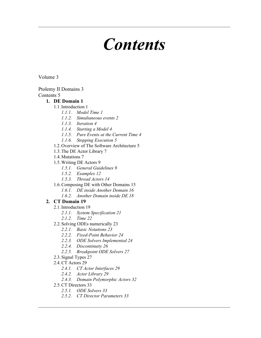
Contents
1. DE Domain 1
1.1. Introduction 1
1.1.1. Model Time 1
1.1.2. Simultaneous events 2
1.1.3. Iteration 4
1.1.4. Starting a Model 4
1.1.5. Pure Events at the Current Time 4
1.1.6. Stopping Execution 5
1.2. Overview of The Software Architecture 5
1.3. The DE Actor Library 7
1.4. Mutations 7
1.5. Writing DE Actors 9
1.5.1. General Guidelines 9
1.5.2. Examples 12
1.5.3. Thread Actors 14
1.6. Composing DE with Other Domains 15
1.6.1. DE inside Another Domain 16
1.6.2. Another Domain inside DE 18
2. CT Domain 19
2.1. Introduction 19
2.1.1. System Specification 21
2.1.2. Time 22
2.2. Solving ODEs numerically 23
2.2.1. Basic Notations 23
2.2.2. Fixed-Point Behavior 24
2.2.3. ODE Solvers Implemented 24
2.2.4. Discontinuity 26
2.2.5. Breakpoint ODE Solvers 27
2.3. Signal Types 27
2.4. CT Actors 29
2.4.1. CT Actor Interfaces 29
2.4.2. Actor Library 29
2.4.3. Domain Polymorphic Actors 32
2.5. CT Directors 33
2.5.1. ODE Solvers 33
2.5.2. CT Director Parameters 33
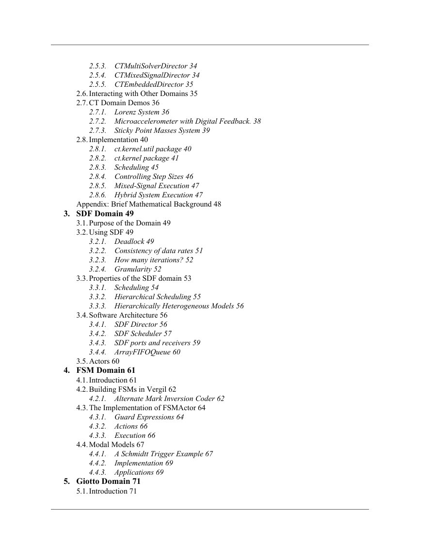
2.5.3. CTMultiSolverDirector 34
2.5.4. CTMixedSignalDirector 34
2.5.5. CTEmbeddedDirector 35
2.6. Interacting with Other Domains 35
2.7. CT Domain Demos 36
2.7.1. Lorenz System 36
2.7.2. Microaccelerometer with Digital Feedback. 38
2.7.3. Sticky Point Masses System 39
2.8. Implementation 40
2.8.1. ct.kernel.util package 40
2.8.2. ct.kernel package 41
2.8.3. Scheduling 45
2.8.4. Controlling Step Sizes 46
2.8.5. Mixed-Signal Execution 47
2.8.6. Hybrid System Execution 47
3. SDF Domain 49
3.1. Purpose of the Domain 49
3.2. Using SDF 49
3.2.1. Deadlock 49
3.2.2. Consistency of data rates 51
3.2.3. How many iterations? 52
3.2.4. Granularity 52
3.3. Properties of the SDF domain 53
3.3.1. Scheduling 54
3.3.2. Hierarchical Scheduling 55
3.3.3. Hierarchically Heterogeneous Models 56
3.4. Software Architecture 56
3.4.1. SDF Director 56
3.4.2. SDF Scheduler 57
3.4.3. SDF ports and receivers 59
3.4.4. ArrayFIFOQueue 60
3.5. Actors 60
4. FSM Domain 61
4.1. Introduction 61
4.2. Building FSMs in Vergil 62
4.2.1. Alternate Mark Inversion Coder 62
4.3. The Implementation of FSMActor 64
4.3.1. Guard Expressions 64
4.3.2. Actions 66
4.3.3. Execution 66
4.4. Modal Models 67
4.4.1. A Schmidtt Trigger Example 67
4.4.2. Implementation 69
4.4.3. Applications 69
5. Giotto Domain 71
5.1. Introduction 71
5.2. Using Giotto 71
5.3. Interacting with Other Domains 74
5.3.1. Giotto Embedded in DE and CT 74
5.3.2. FSM and SDF embedded inside Giotto 76
5.4. Software structure of the Giotto Domain and implementation 77
5.4.1. GiottoDirector 78
5.4.2. GiottoScheduler 79
5.4.3. GiottoReceiver 80
5.4.4. GiottoCodeGenerator 81
6. Rendezvous Domain 83
6.1. Introduction 83
6.2. Properties of the Rendezvous Domain 84
6.2.1. Atomic Communication 84
6.2.2. Nondeterministic Choice of Possible Communications 85
6.2.3. Communication Primitives 85
6.2.4. Stop and Deadlock 85
6.3. Communication Primitives 85
6.3.1. Put-to-all and Get-from-all 86
6.3.2. Put-to-any and Get-from-any 86
6.3.3. Get-from-any-put-to-all 86
6.4. Barrier and Merge 86
6.4.1. Barrier 86
6.4.2. Merge 87
6.4.3. Combining Barrier and Merge 87
6.5. The Rendezvous Software Architecture 87
6.5.1. Class Structure 87
6.5.2. Starting the model 88
6.5.3. Atomic Communication in Concurrent Execution 90
6.5.4. Detecting Deadlocks: 90
6.6. Application to Resource Management 90
6.6.1. Resource Management Demo 90
6.6.2. ResourcePool 91
6.7. Threads in an Actor 91
6.7.1. Creating Extra Threads in an Actor 91
6.7.2. Manually Blocking and Unblocking Threads 91
7. CSP Domain 93
7.1. Introduction 93
7.2. Properties of the CSP Domain 94
7.2.1. Atomic Communication: Rendezvous 94
7.2.2. Choice: Nondeterministic Rendezvous 94
7.2.3. Deadlock 96
7.2.4. Time 96
7.2.5. Differences from Original CSP Model as Proposed by Hoare 97
7.3. Using CSP 97
7.3.1. Unconditional vs. Conditional Rendezvous 97
7.3.2. Time 99
7.4. The CSP Software Architecture 100
7.4.1. Class Structure 100
7.4.2. Starting the model 100
7.4.3. Detecting deadlocks: 102
7.4.4. Terminating the model 103
7.4.5. Pausing/Resuming the Model 103
7.5. Example CSP Applications 104
7.5.1. Dining Philosophers 104
7.5.2. Hardware Bus Contention 105
7.6. Technical Details 105
7.6.1. Rendezvous Algorithm 105
7.6.2. Conditional Communication Algorithm 106
7.6.3. Modification of Rendezvous Algorithm 110
8. DDE Domain 111
8.1. Introduction 111
8.2. Using DDE 111
8.2.1. DDEActor 112
8.2.2. DDEIOPort 112
8.2.3. Feedback Topologies 112
8.3. Properties of the DDE domain 113
8.3.1. Enabling Communication: Advancing Time 113
8.3.2. Maintaining Communication: Null Tokens 114
8.3.3. Alternative Distributed Discrete Event Methods 116
8.4. The DDE Software Architecture 117
8.4.1. Local Time Management 117
8.4.2. Detecting Deadlock 118
8.4.3. Ending Execution 118
8.5. Example DDE Applications 119
9. PN Domain 121
9.1. Introduction 121
9.2. Using PN 122
9.2.1. Deadlock in Feedback Loops 122
9.2.2. Designing Actors 122
9.3. Properties of the PN domain 122
9.3.1. Asynchronous Communication 122
9.3.2. Bounded Memory Execution 123
9.3.3. Time 123
9.3.4. Mutations 124
9.3.5. Hierarchy 124
9.4. The PN Software Architecture 124
9.4.1. PNDirector 124
9.4.2. TimedPNDirector 125
9.4.3. PNQueueReceiver 125
9.4.4. Handling Deadlock 126
9.4.5. Finite Iterations 126
9.4.6. NondeterministicMerge 126
10. PSDF Domain 127
10.1. Purpose of the Domain 127
10.2. Using PSDF 127
10.2.1. Restricted Reconfiguration 128
10.2.2. Symbolic scheduling limitations 129
10.3. Properties of the PSDF domain 129
10.3.1. Scheduling 129
10.3.2. Local Synchrony and Reconfiguration Analysis 130
10.4. Software Architecture 131
10.5. Actors 131
11. DDF Domain 133
11.1. Introduction 133
11.2. Properties of the DDF domain 133
11.2.1. Firing Rules 134
11.2.2. Scheduling 134
11.3. Software Architecture and Implementation 136
11.3.1. DDFDirector 136
11.3.2. Writing DDF Actors 137
11.4. Example DDF Applications 139
11.4.1. Conditionals with If-Else Structure 139
11.4.2. Data-Dependent Iterations 140
11.4.3. Recursion 142
12. HDF Domain 143
12.1. Introduction 143
12.2. Using HDF in Vergil 143
12.2.1. Data Rates of the Modal Model 143
12.2.2. Multi-Token Syntax in Guard Expressions 144
12.2.3. Actions in Modal Model 145
12.3. Properties of the HDF domain 145
12.3.1. Scheduling 145
12.3.2. Hierarchical Heterogeneous Models 145
12.4. Software Architecture 145
12.4.1. HDF Director 145
12.4.2. HDFFSM Director 146
12.5. Actors 146
1 DE Domain
1.1 Introduction
1.1.1 Model Time
1.1.2 Simultaneous events
FIGURE 1.1. If there are simultaneous events at B and D, then the one at B will have higher prior...
FIGURE 1.2. An example of a directed zero-delay loop.
FIGURE 1.3. A Delay actor can be used to break a zero-delay loop.
1.1.3 Iteration
1.1.4 Starting a Model
1.1.5 Pure Events at the Current Time
1.1.6 Stopping Execution
1.2 Overview of The Software Architecture
FIGURE 1.4. UML static structure diagram for the DE kernel package.
1.3 The DE Actor Library
FIGURE 1.5. The library of DE-specific actors.
1.4 Mutations
FIGURE 1.6. Topology before and after mutation for the example in figure 1.7.
FIGURE 1.7. An example of a class that constructs a model and then mutates it.
1.5 Writing DE Actors
1.5.1 General Guidelines
1.5.2 Examples
TimedDelay Actor
FIGURE 1.8. A domain-specific actor, TimedDelay actor, in DE.
Server Actor
FIGURE 1.9. Code for the Server actor. For more details, see the source code.
1.5.3 Thread Actors
FIGURE 1.10. Code listings for two style of writing the ABRecognizer actor.
FIGURE 1.11. The run() method of the ABRO actor.
1.6 Composing DE with Other Domains
FIGURE 1.12. An example of heterogeneous and hierarchical composition. The CT subsystem and DE su...
1.6.1 DE inside Another Domain
1.6.2 Another Domain inside DE
2 CT Domain
2.1 Introduction
(1)
FIGURE 2.1. Possible implementations of the system equations.
(2)
(3)
(4)
, (5)
. (6)
, (7)
(8)
2.1.1 System Specification
1. The signal-flow model is more abstract. Ptolemy II focuses on system-level design and behavior...
2. The signal flow model is more flexible and extensible, in the sense that it is easy to embed c...
3. The signal flow model is consistent with other models of computation in Ptolemy II. Most model...
4. The signal flow model is compatible with the conservation law model. For physical systems that...
FIGURE 2.2. A conceptual block diagram for continuous time systems.
FIGURE 2.3. The block diagram for the example system.
(9)
2.1.2 Time
2.2 Solving ODEs numerically
2.2.1 Basic Notations
, (10)
, (11)
2.2.2 Fixed-Point Behavior
. (12)
(13)
(14)
, (15)
(16)
2.2.3 ODE Solvers Implemented
1. Forward Euler solver:
(17)
2. 2(3)-order Explicit Runge-Kutta solver
(18)
(19)
(20)
3. 4(5)-order Explicit Runge-Kutta solver
(21)
(22)
(23)
4. Backward Euler solver:
(24)
5. Trapezoidal Rule solver:
. (25)
2.2.4 Discontinuity
2.2.5 Breakpoint ODE Solvers
2.3 Signal Types
FIGURE 2.4. A signal type lattice.
2.4 CT Actors
2.4.1 CT Actor Interfaces
2.4.2 Actor Library
(26)
(27)
(28)
2.4.3 Domain Polymorphic Actors
2.5 CT Directors
2.5.1 ODE Solvers
2.5.2 CT Director Parameters
Table 13: CTDirector Parameters
2.5.3 CTMultiSolverDirector
Table 14: Additional Parameter for CTMultiSolverDirector
2.5.4 CTMixedSignalDirector
Table 15: Additional Parameter for CTMixedSignalDirector
2.5.5 CTEmbeddedDirector
2.6 Interacting with Other Domains
FIGURE 2.5. Embedding a DE component in a CT system.
FIGURE 2.6. Embedding a CT component in a DE system.
FIGURE 2.7. Hybrid system modeling.
2.7 CT Domain Demos
2.7.1 Lorenz System
(29)
FIGURE 2.8. Block diagram for the Lorenz system.
FIGURE 2.9. The simulation result of the Lorenz system.
2.7.2 Microaccelerometer with Digital Feedback.
FIGURE 2.10. Micro-accelerator with digital feedback
FIGURE 2.11. Block diagram for the micro-accelerator system.
FIGURE 2.12. Execution result of the microaccelerometer system.
2.7.3 Sticky Point Masses System
FIGURE 2.13. Sticky point masses system
FIGURE 2.14. Modeling sticky point masses.
FIGURE 2.15. The simulation result of the sticky point masses system.
2.8 Implementation
FIGURE 2.16. The packages in the CT domain.
2.8.1 ct.kernel.util package
FIGURE 2.17. UML for ct.kernel.util package.
2.8.2 ct.kernel package
FIGURE 2.18. UML for ct.kernel package, actor related classes.
FIGURE 2.19. UML for ct.kernel package, director related classes.
FIGURE 2.20. UML for ct.kernel.solver package.
2.8.3 Scheduling
1. Given the state of the system at time points , if the current integration step size is , i.e. ...
2. After the new state is computed, test whether this step is successful. Local truncation error ...
3. If the step is successful, predict the next step size. Otherwise, reduce the step size and try...
FIGURE 2.21. A chain of integrators.
2.8.4 Controlling Step Sizes
. (30)
2.8.5 Mixed-Signal Execution
DE inside CT
CT inside DE
(31)
2.8.6 Hybrid System Execution
Appendix A: Brief Mathematical Background
Theorem 1. [Existence and uniqueness of the solution of an ODE
. (32)
1. [Continuity Condition] Let D be the set of possible discontinuity points; it may be empty. For...
2. [Lipschitz Condition] There is a piecewise continuous bounded function :, where is the set of ...
. (33)
(34)
. (35)
u
Theorem 2. [Contraction Mapping Theorem.
(36)
3 SDF Domain
3.1 Purpose of the Domain
3.2 Using SDF
3.2.1 Deadlock
FIGURE 3.1. An SDF model that deadlocks.
FIGURE 3.2. The model of figure 3.1 corrected with an instance of SampleDelay in the feedback loop.
3.2.2 Consistency of data rates
FIGURE 3.3. An SDF model with inconsistent rates.
FIGURE 3.4. Figure 3.3 modified to have consistent rates.
3.2.3 How many iterations?
FIGURE 3.5. A model that plots the Fast Fourier Transform of a signal. Only one iteration must be...
FIGURE 3.6. A model that plots the values of a signal. 256 iterations must be executed to plot th...
3.2.4 Granularity
FIGURE 3.7. A model that implements a block FIR filter. The vectorizationFactor parameter of the ...
3.3 Properties of the SDF domain
3.3.1 Scheduling
FIGURE 3.8. An example SDF model. The model has a toplevel named E0, an SDF Director named D1 and...
Firings(A) ¥ ProductionRate(A1) = Firings(B) ¥ ConsumptionRate(B1)
Firings(A) ¥ ProductionRate(A2) = Firings(C) ¥ ConsumptionRate(C1)
Firings(C) ¥ ProductionRate(C2) = Firings(B) ¥ ConsumptionRate(B2)
FIGURE 3.9. A consistent cyclic graph, properly annotated with delays. A one token delay is repre...
FIGURE 3.10. Two models, with each port annotated with the appropriate rate properties. The model...
3.3.2 Hierarchical Scheduling
3.3.3 Hierarchically Heterogeneous Models
3.4 Software Architecture
FIGURE 3.11. The static structure of the SDF kernel classes.
3.4.1 SDF Director
3.4.2 SDF Scheduler
FIGURE 3.12. The sequence of method calls during scheduling of a hierarchical model.
Multiports
Dangling ports
3.4.3 SDF ports and receivers
3.4.4 ArrayFIFOQueue
3.5 Actors
4 FSM Domain
4.1 Introduction
4.2 Building FSMs in Vergil
4.2.1 Alternate Mark Inversion Coder
1. Start Vergil, open a graph editor by selecting File -> New -> Graph Editor.
2. From MoreLibraries/Automata in the palette on the left, drag an FSM actor to the graph. Rename...
3. Right click on AMICoder, select Customize -> Ports. Add an input port with name in and an outp...
4. Right click on AMICoder, select Open Actor. This will open an FSM editor for AMICoder. Note th...
5. From the palette on the left, drag a state to the graph, rename it Positive. Drag another stat...
6. Control-drag from the Positive state to the Negative state to create a transition.
7. Double click on the transition. This will bring up the dialog box shown in figure 4.1 for edit...
FIGURE 4.1. The dialog box for editing parameters of a transition.
8. Set guardExpression to in�==�1, and outputActions to out�=�1 and hit the Commit button.
9. Create a transition from the Positive state back to itself with guard expression in�==�0 and o...
10. Create a transition from the Negative state back to itself with guard expression in�==�0 and ...
11. Create a transition from the Negative state to the Positive state with guard expression in�==...
12. The construction of AMICoder is complete. It will look like what is shown in figure 4.2.
FIGURE 4.2. Vergil FSM editor showing the AMICoder.
13. Return to the graph editor opened in step 1.
14. Drag a Pulse actor (from Actors/Sources/SequenceSources), a SequencePlotter (from Actors/ Sin...
15. Connect the actors as shown in figure 4.3.
FIGURE 4.3. An SDF model with the AMICoder.
16. Edit parameters of the Pulse actor: set indexes to {0,�1,�2,�3,�4,�5}; set values to {0,�1,�1...
17. The model construction is complete.
18. Select View -> Run Window from the menu. Set director iterations to 6 and execute the model. ...
4.3 The Implementation of FSMActor
FIGURE 4.4. The UML static structure diagram of FSMActor-related classes.
4.3.1 Guard Expressions
4.3.2 Actions
4.3.3 Execution
4.4 Modal Models
FIGURE 4.5. A modal model example.
4.4.1 A Schmidtt Trigger Example
1. Open a Vergil graph editor. From Actors/HigherOrderActors, drag a ModalModel actor to the grap...
2. Look inside SchmidttTrigger. This will open an FSM editor for the mode controller. Construct a...
FIGURE 4.6. The mode controller for SchmidttTrigger.
3. Right click on the state named P, select Add Refinement. Specify the name of the refinement as...
FIGURE 4.7. Model for the refinements in SchmidttTrigger. RefinementP has Const set to 1.0, Refin...
4. Add a refinement named RefinementN to state N. Build a model for it similar to the one shown i...
5. Back to the graph editor opened in step 1. Build the model as shown in figure 4.8. The model g...
FIGURE 4.8. The top-level model with the SchmidttTrigger.
6. Run the model for 200 iterations. A sample result is shown in figure 4.9.
FIGURE 4.9. Sample result of the model shown in figure 4.8.
4.4.2 Implementation
FIGURE 4.10. FSM kernel classes that support modal models.
1. The FSM director transfers the input tokens from the outside domain to the mode controller and...
2. The preemptive transitions from the current state of the mode controller are examined. If ther...
3. Fire the refinement of the current state.
4. The non-preemptive transitions from the current state of the mode controller are examined. If ...
5. Any output token produced by the mode controller or the refinement is transferred to the outsi...
1. Execute the commit actions of the transition.
2. Set the current state of the mode controller to the destination state of the transition.
3. If the value of the reset parameter of the transition is true, the refinement of the destinati...
4.4.3 Applications
Hybrid System Modeling
Multirate System Modeling
Communication Protocol Modeling
5 Giotto Domain
5.1 Introduction
5.2 Using Giotto
FIGURE 5.1. A Simple Giotto model with only one mode.
FIGURE 5.2. Simulation results for the model in Figure 5.1
FIGURE 5.3. Generated Giotto code for the model in Figure 5.1
5.3 Interacting with Other Domains
5.3.1 Giotto Embedded in DE and CT
FIGURE 5.4. Giotto model embedded in DE model.
FIGURE 5.5. Simulation results of model of Figure 5.4
5.3.2 FSM and SDF embedded inside Giotto
FIGURE 5.6. Modal model embedded in Giotto model.
5.4 Software structure of the Giotto Domain and implementation
FIGURE 5.7. Simulation results for model in Figure 5.6.
5.4.1 GiottoDirector
FIGURE 5.8. The static structure of the Giotto package kernel classes.
5.4.2 GiottoScheduler
FIGURE 5.9. Schedule computation of GiottoScheduler.
5.4.3 GiottoReceiver
FIGURE 5.10. Working mechanism of GiottoReceiver.
5.4.4 GiottoCodeGenerator
6 Rendezvous Domain
6.1 Introduction
6.2 Properties of the Rendezvous Domain
6.2.1 Atomic Communication
FIGURE 6.1. Illustrating how processes block waiting to rendezvous
6.2.2 Nondeterministic Choice of Possible Communications
6.2.3 Communication Primitives
6.2.4 Stop and Deadlock
6.3 Communication Primitives
6.3.1 Put-to-all and Get-from-all
6.3.2 Put-to-any and Get-from-any
6.3.3 Get-from-any-put-to-all
6.4 Barrier and Merge
6.4.1 Barrier
FIGURE 6.2. The Barrier actor
6.4.2 Merge
FIGURE 6.3. The Merge actor
6.4.3 Combining Barrier and Merge
FIGURE 6.4. Using a Barrier and a Merge to express complex synchronization logic
6.5 The Rendezvous Software Architecture
6.5.1 Class Structure
FIGURE 6.5. Static structure diagram for classes in the Rendezvous kernel.
6.5.2 Starting the model
FIGURE 6.6. Sequence of steps involved in setting up and controlling the model.
6.5.3 Atomic Communication in Concurrent Execution
6.5.4 Detecting Deadlocks:
6.6 Application to Resource Management
6.6.1 Resource Management Demo
6.6.2 ResourcePool
6.7 Threads in an Actor
6.7.1 Creating Extra Threads in an Actor
6.7.2 Manually Blocking and Unblocking Threads
7 CSP Domain
7.1 Introduction
7.2 Properties of the CSP Domain
7.2.1 Atomic Communication: Rendezvous
FIGURE 7.1. Illustrating how processes block waiting to rendezvous
7.2.2 Choice: Nondeterministic Rendezvous
CIF:
CDO:
FIGURE 7.2. Example of how a CDO might be used in a buffer.
7.2.3 Deadlock
7.2.4 Time
7.2.5 Differences from Original CSP Model as Proposed by Hoare
7.3 Using CSP
7.3.1 Unconditional vs. Conditional Rendezvous
FIGURE 7.3. Template for executing a CDO construct.
FIGURE 7.4. Code used to implement the buffer process described in figure 7.3.
7.3.2 Time
7.4 The CSP Software Architecture
7.4.1 Class Structure
FIGURE 7.5. Static structure diagram for classes in the CSP kernel.
CSPDirector:
CSPReceiver:
CSPActor:
ConditionalReceive, ConditionalSend:
7.4.2 Starting the model
FIGURE 7.6. Sequence of steps involved in setting up and controlling the model.
FIGURE 7.7. Code executed by ProcessThread.run().
7.4.3 Detecting deadlocks:
7.4.4 Terminating the model
7.4.5 Pausing/Resuming the Model
7.5 Example CSP Applications
7.5.1 Dining Philosophers
Nondeterministic Resource Contention
FIGURE 7.8. Illustration of the dining philosophers problem.
7.5.2 Hardware Bus Contention
Deterministic Resource Contention
FIGURE 7.9. Illustration of the Hardware Bus Contention example.
7.6 Technical Details
7.6.1 Rendezvous Algorithm
FIGURE 7.10. Rendezvous algorithm.
7.6.2 Conditional Communication Algorithm
Built on top of rendezvous:
FIGURE 7.11. Conceptual view of how conditional communication is built on top of rendezvous.
Choosing which branch succeeds
Algorithm used by each branch:
FIGURE 7.12. Algorithm used to determine if a conditional rendezvous branch succeeds or fails
7.6.3 Modification of Rendezvous Algorithm
FIGURE 7.13. Modification of rendezvous algorithm, section 7.6.3, shown in ellipse.
8 DDE Domain
8.1 Introduction
8.2 Using DDE
8.2.1 DDEActor
getNextToken()
getLastPort()
8.2.2 DDEIOPort
8.2.3 Feedback Topologies
FIGURE 8.1. Initializing feedback topologies.
8.3 Properties of the DDE domain
8.3.1 Enabling Communication: Advancing Time
Communicating Tokens
Communicating Time
FIGURE 8.2. DDE actors and local time.
8.3.2 Maintaining Communication: Null Tokens
FIGURE 8.3. Timed deadlock (feedforward).
FIGURE 8.4. Timed deadlock (feedback).
Preventing Feedforward Timed Deadlock
Preventing Feedback Timed Deadlock
8.3.3 Alternative Distributed Discrete Event Methods
8.4 The DDE Software Architecture
8.4.1 Local Time Management
FIGURE 8.5. Key classes for managing time locally.
8.4.2 Detecting Deadlock
FIGURE 8.6. Additional classes in the DDE kernel.
8.4.3 Ending Execution
8.5 Example DDE Applications
FIGURE 8.7. Localized Zeno condition topology.
9 PN Domain
9.1 Introduction
9.2 Using PN
9.2.1 Deadlock in Feedback Loops
9.2.2 Designing Actors
9.3 Properties of the PN domain
9.3.1 Asynchronous Communication
9.3.2 Bounded Memory Execution
9.3.3 Time
1. The process is delayed and is explicitly waiting for time to advance (delay block).
2. The process is waiting for data to arrive on one of its input channels (read block).
9.3.4 Mutations
9.3.5 Hierarchy
9.4 The PN Software Architecture
FIGURE 9.1. Static structure of the PN kernel.
9.4.1 PNDirector
9.4.2 TimedPNDirector
9.4.3 PNQueueReceiver
9.4.4 Handling Deadlock
9.4.5 Finite Iterations
9.4.6 NondeterministicMerge
10 PSDF Domain
10.1 Purpose of the Domain
10.2 Using PSDF
10.2.1 Restricted Reconfiguration
FIGURE 10.1. A PSDF model that is not locally synchronous.
FIGURE 10.2. The model of figure 10.1 corrected using hierarchy.
10.2.2 Symbolic scheduling limitations
10.3 Properties of the PSDF domain
10.3.1 Scheduling
FIGURE 10.3. An example SDF model.
Firings(A) ¥ ProductionRate(A1) = Firings(B) ¥ ConsumptionRate(B1)
Firings(A) ¥ ProductionRate(A2) = Firings(C) ¥ ConsumptionRate(C1)
Firings(C) ¥ ProductionRate(C2) = Firings(B) ¥ ConsumptionRate(B2)
Firings(A) = ConsumptionRate(B1) / (gcd(ConsumptionRate(C1) * ProductionRate(A1) / gcd(Production...
10.3.2 Local Synchrony and Reconfiguration Analysis
10.4 Software Architecture
10.5 Actors
11 DDF Domain
11.1 Introduction
11.2 Properties of the DDF domain
11.2.1 Firing Rules
11.2.2 Scheduling
1. After any finite time the token sequence (including consumed tokens) on any channel is a prefi...
2. The scheduler should be able to execute a graph forever if it is possible to execute a graph f...
3. The scheduler should be able to execute a graph forever in bounded memory if it is possible to...
4. The scheduler should execute the graph in a sequence of well-defined and determinate iteration...
FIGURE 11.1. The pseudo-code of the scheduling algorithm implemented in the DDF domain.
11.3 Software Architecture and Implementation
11.3.1 DDFDirector
11.3.2 Writing DDF Actors
FIGURE 11.2. Initialization code of DDFBooleanSelect actor.
FIGURE 11.3. Split-phase firing code of DDFBooleanSelect actor.
FIGURE 11.4. Rate update code of DDFBooleanSelect actor.
FIGURE 11.5. Initialization of ArrayTokens and their exemplary uses for the DDFSelect actor.
11.4 Example DDF Applications
11.4.1 Conditionals with If-Else Structure
FIGURE 11.6. A model illustrating if-then-else structure.
11.4.2 Data-Dependent Iterations
FIGURE 11.7. A model illustrating do-while structure.
11.4.3 Recursion
FIGURE 11.8. A model illustrating recursion structure for computing prime numbers.
12 HDF Domain
12.1 Introduction
12.2 Using HDF in Vergil
12.2.1 Data Rates of the Modal Model
FIGURE 12.1. An HDF model example.
12.2.2 Multi-Token Syntax in Guard Expressions
12.2.3 Actions in Modal Model
12.3 Properties of the HDF domain
12.3.1 Scheduling
12.3.2 Hierarchical Heterogeneous Models
12.4 Software Architecture
12.4.1 HDF Director
12.4.2 HDFFSM Director
12.5 Actors
References
[1] G. Agha, Actors: A Model of Concurrent Computation in Distributed Systems, MIT Press, Cambrid...
[2] G. Agha, “Abstracting Interaction Patterns: A Programming Paradigm for Open Distributed Syste...
[3] G. Agha, “Concurrent object-oriented programming,” Communications of the ACM, 33(9):125– 140,...
[4] G. Agha, S. Frolund, W. Kim, R. Panwar, A. Patterson, and D. Sturman, “Abstraction and modula...
[5] G. Agha, I. A. Mason, S. F.Smith, and C. L. Talcott, “A foundation for actor computation. Jou...
[6] R. Allen and D. Garlan, “Formalizing Architectural Connection,” in Proc. of the 16th Internat...
[7] G. R. Andrews, Concurrent Programming — Principles and Practice, Addison-Wesley, 1991.
[8] R. L. Bagrodia, “Parallel Languages for Discrete Event Simulation Models,” IEEE Computational...
[9] R. Bagrodia, R. Meyer, et al., “Parsec: A Parallel Simulation Environment for Complex Systems...
[10] P. Baldwin, S. Kohli, E. A. Lee, X. Liu and Y. Zhao, “Modeling of Sensor Nets in Ptolemy II,...
[11] P. Baldwin, S. Kohli, E. A. Lee, X. Liu and Y. Zhao, “Visualsense: Visual Modeling for Wirel...
[12] M. von der Beeck, “A Comparison of Statecharts Variants,” in Proc. of Formal Techniques in R...
[13] A. Benveniste and G. Berry, “The Synchronous Approach to Reactive and Real-Time Systems,” Pr...
[14] A. Benveniste and P. Le Guernic, “Hybrid Dynamical Systems Theory and the SIGNAL Language,” ...
[15] G. Berry and G. Gonthier, “The Esterel synchronous programming language: Design, semantics, ...
[16] S. Bhatt, R. M. Fujimoto, A. Ogielski, and K. Perumalla, “Parallel Simulation Techniques for...
[17] S. S. Bhattacharyya, P. K. Murthy and E. A. Lee, Software Synthesis from Dataflow Graphs, Kl...
[18] J. Bier, E. Goei, W. Ho, P. Lapsley, M. O'Reilly, G. Sih and E. A. Lee, “Gabriel: A Design E...
[19] C. H. Brooks and E. A. Lee, “Ptolemy II Coding Style,” Technical Memorandum UCB/ERL M03/44, ...
[20] Randy Brown, “CalendarQueue: A Fast Priority Queue Implementation for The Simulation Event S...
[21] V. Bryant, “Metric Spaces,” Cambridge University Press, 1985.
[22] J. T. Buck, “Scheduling Dynamic Dataflow Graphs with Bounded Memory Using the Token Flow Mod...
[23] J. T. Buck, S. Ha, E. A. Lee, and D. G. Messerschmitt, “Ptolemy: A Framework for Simulating ...
[24] A. Burns, Programming in OCCAM 2, Addison-Wesley, 1988.
[25] James C. Candy, “A Use of Limit Cycle Oscillations to Obtain Robust Analog-to-Digital Conver...
[26] A. Cataldo, C. Hylands, E. A. Lee, J. Liu, X. Liu, S. Neuendorffer and H. Zheng, “Hyvisual: ...
[27] A. Cataldo, E. Lee, X. Liu, E. Matsikoudis and H. Zheng, “Discrete-Event Systems: Generalizi...
[28] L. Cardelli, Type Systems, Handbook of Computer Science and Engineering, CRC Press, 1997.
[29] P. Caspi, D. Pilaud, N. Halbwachs, and J. A. Plaice, “LUSTRE: A Declarative Language for Pro...
[30] K. M. Chandy and J. Misra, “Asynchronous Distributed Simulation Via a Sequence of Parallel C...
[31] I. Craig, The Interpretation of Object-Oriented Programming Languages, Springer-Verlag, 2001.
[32] B. A. Davey and H. A. Priestly, Introduction to Lattices and Order, Cambridge University Pre...
[33] John Davis II, "Order and Containment in Concurrent System Design," Ph.D. thesis, Memorandum...
[34] S. A. Edwards and E. A. Lee, “The Semantics and Execution of a Synchronous Block-Diagram Lan...
[35] S. A. Edwards, “The Specification and Execution of Heterogeneous Synchronous Reactive System...
[36] J. Eker, J. W. Janneck, E. A. Lee, J. Liu, X. Liu, J. Ludvig, S. Neuendorffer, S. Sachs, Y. ...
[37] J. Eker and J. W. Janneck, “Cal Language Report: Specification of the Cal Actor Language,” T...
[38] P. H. J. van Eijk, C. A. Vissers, M. Diaz, The formal description technique LOTOS, Elsevier ...
[39] R. Esser, “An Object Oriented Petri Net Approach to Embedded System Design,” Ph.D. Thesis, E...
[40] P. A. Fishwick, Simulation Model Design and Execution: Building Digital Worlds, Prentice Hal...
[41] C. Fong, "Discrete-Time Dataflow Models for Visual Simulation in Ptolemy II," Master's Repor...
[42] M. Fowler and K. Scott, UML Distilled, Addison-Wesley, 1997.
[43] R. M. Fujimoto, “Parallel Discrete Event Simulation,” Communications of the ACM, vol. 33, no...
[44] E. Gamma, R. Helm, R. Johnson, and J. Vlissides, Design Patterns: Elements of Reusable Objec...
[45] C. W. Gear, “Numerical Initial Value Problems in Ordinary Differential Equations,” Prentice ...
[46] A. J. C. van Gemund, “Performance Prediction of Parallel Processing Systems: The PAMELA Meth...
[47] A. Girault, B. Lee, and E. A. Lee, “Hierarchical Finite State Machines with Multiple Concurr...
[48] M. Goel, Process Networks in Ptolemy II, MS Report, ERL Technical Report UCB/ERL No. M98/69,...
[49] G. Goessler and A. Sangiovanni-Vincentelli, “Compositional Modeling in Metropolis,” In Proce...
[50] M. Grand, Patterns in Java, Volume 1, A Catalog of Reusable Design Patterns Illustrated with...
[51] C. Hansen, “Hardware logic simulation by compilation,” In Proceedings of the Design Automati...
[52] D. Harel, “Statecharts: A Visual Formalism for Complex Systems,” Sci. Comput. Program., vol ...
[53] P. G. Harrison, “A Higher-Order Approach to Parallel Algorithms,” The Computer Journal, Vol....
[54] T. A. Henzinger, B. Horowitz and C. M. Kirsch, “Giotto: A Time-Triggered Language for Embedd...
[55] T. A. Henzinger, “The theory of hybrid automata,” in Proceedings of the 11th Annual Symposiu...
[56] T.A. Henzinger, and O. Kupferman, and S. Qadeer, “From prehistoric to postmodern symbolic mo...
[57] T. A. Henzinger and C. M. Kirsch, “The Embedded Machine: Predictable, portable real-time cod...
[58] C. Hewitt, “Viewing control structures as patterns of passing messages,” Journal of Artifici...
[59] M. G. Hinchey and S. A. Jarvis, Concurrent Systems: Formal Developments in CSP, McGraw- Hill...
[60] C. W. Ho, A. E. Ruehli, and P. A. Brennan, “The Modified Nodal Approach to Network Analysis,...
[61] C. A. R. Hoare, “Communicating Sequential Processes,” Communications of the ACM, Vol. 21, No...
[62] C. A. R. Hoare, Communicating Sequential Processes, Prentice-Hall, 1985.
[63] IEEE DASC 1076.1 Working Group, “VHDL-A Design Objective Document, version 2.3,” http:/ /www...
[64] D. Jefferson, Brian Beckman, et al, “Distributed Simulation and the Time Warp Operating Syst...
[65] G. Kahn, “The Semantics of a Simple Language for Parallel Programming,” Proc. of the IFIP Co...
[66] G. Kahn and D. B. MacQueen, “Coroutines and Networks of Parallel Processes,” Information Pro...
[67] G. Karsai, M. Maroti, Á. Lédeczi, J. Gray and J. Sztipanovits, “Type Hierarchies and Composi...
[68] G. Karsai, “A Configurable Visual Programming Environment: A Tool for Domain-Specific Progra...
[69] E. Kohler, The Click Modular Router, Ph.D. Thesis, Massachusetts Institute of Technology, De...
[70] H. Kopetz, Real-Time Systems: Design Principles for Distributed Embedded Applications, Kluwe...
[71] P. Laramie, R.S. Stevens, and M.Wan, “Kahn process networks in Java,” ee290n class project r...
[72] D. Lea, Concurrent Programming in JavaTM, Addison-Wesley, Reading, MA, 1997.
[73] B. Lee and E. A. Lee, “Interaction of Finite State Machines with Concurrency Models,” Proc. ...
[74] B. Lee and E. A. Lee, “Hierarchical Concurrent Finite State Machines in Ptolemy,” Proc. of I...
[75] E. A. Lee and S. Neuendorffer, “Classes and Subclasses in Actor-Oriented Design,” In Proceed...
[76] E. A. Lee and Y. Xiong, “A Behavioral Type System and Its Application in Ptolemy II,” Formal...
[77] E. A. Lee, S. Neuendorffer and M. J. Wirthlin, “Actor-Oriented Design of Embedded Hardware a...
[78] E. A. Lee, “Embedded Software,” in Advances in Computers (M. Zelkowitz, editor), Vol. 56, Ac...
[79] E. A. Lee, “A Denotational Semantics for Dataflow with Firing,” Memorandum UCB/ERL M97/ 3, E...
[80] E. A. Lee and T. M. Parks, “Dataflow Process Networks,” in Readings in Hardware/Software Co-...
[81] E. A. Lee, “What's Ahead for Embedded Software?” IEEE Computer, September 2000, pp. 18- 26.
[82] E. A. Lee, “Modeling Concurrent Real-time Processes Using Discrete Events,” Invited paper to...
[83] E. A. Lee and Y. Xiong, “System-Level Types for Component-Based Design,” First Workshop on E...
[84] E. A. Lee, “Computing for Embedded Systems,” invited paper, IEEE Instrumentation and Measure...
[85] E. A. Lee and T. M. Parks, “Dataflow Process Networks,”, Proceedings of the IEEE, vol. 83, n...
[86] E. A. Lee and A. Sangiovanni-Vincentelli, “A Framework for Comparing Models of Computation,”...
[87] E. A. Lee and D. G. Messerschmitt, “Static Scheduling of Synchronous Data Flow Programs for ...
[88] M. A. Lemkin, Micro Accelerometer Design with Digital Feedback Control, Ph.D. dissertation, ...
[89] S. Y. Liao, S. Tjiang, and R. Gupta, “An efficient implementation of reactivity for modeling...
[90] J. Liu, J. Eker, J. W. Janneck and E. A. Lee, “Realistic Simulations of Embedded Control Sys...
[91] J. Liu, X. Liu, and E. A. Lee, “Modeling Distributed Hybrid Systems in Ptolemy II,” invited ...
[92] J. Liu, S. Jefferson, and E. A. Lee, “Motivating Hierarchical Run-Time Models in Measurement...
[93] J. Liu and E. A. Lee, “A Component-Based Approach to Modeling and Simulating Mixed-Signal an...
[94] J. Liu and E. A. Lee, “On the Causality of Mixed-Signal and Hybrid Models,” 6th Internationa...
[95] J. Liu and E. A. Lee, “Timed Multitasking for Real-Time Embedded Software,” IEEE Control Sys...
[96] J. Liu, "Responsible Frameworks for Heterogeneous Modeling and Design of Embedded Systems," ...
[97] J. Liu, Continuous Time and Mixed-Signal Simulation in Ptolemy II, MS Report, UCB/ERL Memora...
[98] J. Liu and E. A. Lee, "Component-based Hierarchical Modeling of Systems with Continuous and ...
[99] J. Liu, X. Liu, T. J. Koo, B. Sinopoli, S. Sastry, and E. A. Lee, "A Hierarchical Hybrid Sys...
[100] X. Liu, J. Liu, J. Eker, and E. A. Lee, “Heterogeneous Modeling and Design of Control Syste...
[101] D. C. Luckham and J. Vera, “An Event-Based Architecture Definition Language,” IEEE Transact...
[102] F. Maraninchi, “The Argos Language: Graphical Representation of Automata and Description of...
[103] S. McConnell, Code Complete: A Practical Handbook of Software Construction, Microsoft Press...
[104] K. Mehlhorn and Stefan Naher. LEDA: A Platform for Combinatorial and Geometric Computing. C...
[105] B. Meyer, Object Oriented Software Construction, 2nd ed., Prentice Hall, 1997.
[106] R. Milner, Communication and Concurrency, Prentice-Hall, Englewood Cliffs, NJ, 1989.
[107] R. Milner, “A Calculus of Communicating Systems”, Lecture Notes in Computer Science, Vol. 9...
[108] R. Milner, A Theory of Type Polymorphism in Programming, Journal of Computer and System Sci...
[109] J. Misra, “Distributed Discrete-Event Simulation,” Computing Surveys, vol. 18, no. 1, March...
[110] L. Muliadi, "Discrete Event Modeling in Ptolemy II," MS Report, Dept. of EECS, University o...
[111] P. K. Murthy and E. A. Lee, “Multidimensional Synchronous Dataflow,” IEEE Transactions on S...
[112] L. W. Nagal, “SPICE2: A Computer Program to Simulate Semiconductor Circuits,” ERL Memo No. ...
[113] NASA Office of Safety and Mission Assurance, Software Formal Inspections Guidebook, August ...
[114] S. Neuendorffer, “Automatic Specialization of Actor-Oriented Models in Ptolemy II,” Master'...
[115] A. R. Newton and A. L. Sangiovanni-Vincentelli, “Relaxation-Based Electrical Simulation,” I...
[116] S. Oaks and H. Wong, Java Threads, O’Reilly, 1997.
[117] OMG, Unified Modeling Language: Superstructure, version 2.0, 3rd revised submission to RFP ...
[118] J. K. Ousterhout, Tcl and the Tk Toolkit, Addison-Wesley, Reading, MA, 1994.
[119] J. K. Ousterhout, Scripting: Higher Level Programming for the 21 Century, IEEE Computer mag...
[120] T. M. Parks, Bounded Scheduling of Process Networks, Technical Report UCB/ERL-95-105. Ph.D....
[121] J. K. Peacock, J. W. Wong and E. G. Manning, “Distributed Simulation Using a Network of Pro...
[122] Rational Software Corporation, UML Notation Guide, Version 1.1, September 1997, http:// www...
[123] J. Reekie, S. Neuendorffer, C. Hylands and E. A. Lee, “Software Practice in the Ptolemy Pro...
[124] J. Rehof and T. Mogensen, “Tractable Constraints in Finite Semilattices,” Third Internation...
[125] J. H. Reppy, “CML: A Higher-Order Concurrent Language,” SIGPLAN Notices, 26(6): 293-305, Ju...
[126] C. Rettig, “Automatic Units Tracking,” Embedded System Programming, March, 2001.
[127] A. J. Riel, Object Oriented Design Heuristics, Addison Wesley, 1996.
[128] R. C. Rosenberg and D.C. Karnopp, Introduction to Physical System Dynamics, McGraw-Hill, NY...
[129] J. Rowson and A. Sangiovanni-Vincentelli, “Interface Based Design,” Proc. of DAC ‘97.
[130] J. Rumbaugh, et al. Object-Oriented Modeling and Design Prentice Hall, 1991.
[131] J. Rumbaugh, OMT Insights, SIGS Books, 1996.
[132] M.A.A. Sanvido, A. Walburg. “Giotto Tutorial. Technical Memorandum,” UCB/ERL M04/30, Univer...
[133] S. Saracco, J. R. W. Smith, and R. Reed, Telecommunications Systems Engineering Using SDL, ...
[134] B. Selic, G. Gullekson, and P. Ward, Real-Time Object-Oriented Modeling, John Wiley & Sons,...
[135] N. Smyth, Communicating Sequential Processes Domain in Ptolemy II, MS Report, UCB/ERL Memor...
[136] I. E. Sutherland, “Sketchpad - a Man-Machine Graphical Communication System,” Technical Rep...
[137] W. R. Sutherland, "The on-Line Graphical Specification of Computer Procedures," Ph.D. Thesi...
[138] J. Teich, E. Zitzler, and S. Bhattacharyya, “3D exploration of software schedules for DSP a...
[139] J. Tsay, “A Code Generation Framework for Ptolemy II,” ERL Technical Report UCB/ERL No. M00...
[140] J. Tsay, C. Hylands and E. A. Lee, "A Code Generation Framework for Java Component-Based De...
[141] P. Whitaker, "The Simulation of Synchronous Reactive Systems In Ptolemy II," Master's Repor...
[142] World Wide Web Consortium, XML 1.0 Recommendation, October 2000, http://www.w3.org/ XML/
[143] World Wide Web Consortium, Overview of SGML Resources, August 2000, http://www.w3.org/ Mark...
[144] Y. Xiong and E. A. Lee, “An Extensible Type System for Component-Based Design,” 6th Interna...
[145] Y. Xiong, “An Extensible Type System for Component-Based Design,” Ph.D. thesis, Technical M...
[146] Y. Zhao, “A Model of Computation with Push and Pull Processing,” Masters Thesis, Technical ...
[147] G. Zhou, “Dynamic Dataflow Modeling in Ptolemy II,” Master's Report, Technical Memorandum N...
Index
Symbols
A
B
C
D
E
F
G
H
I
J
K
L
M
N
O
P
Q
R
S
T
U
V
W
Z




 2023年江西萍乡中考道德与法治真题及答案.doc
 2012年重庆南川中考生物真题及答案.doc
 2013年江西师范大学地理学综合及文艺理论基础考研真题.doc
 2020年四川甘孜小升初语文真题及答案I卷.doc
 2020年注册岩土工程师专业基础考试真题及答案.doc
 2023-2024学年福建省厦门市九年级上学期数学月考试题及答案.doc
 2021-2022学年辽宁省沈阳市大东区九年级上学期语文期末试题及答案.doc
 2022-2023学年北京东城区初三第一学期物理期末试卷及答案.doc
 2018上半年江西教师资格初中地理学科知识与教学能力真题及答案.doc
 2012年河北国家公务员申论考试真题及答案-省级.doc
 2020-2021学年江苏省扬州市江都区邵樊片九年级上学期数学第一次质量检测试题及答案.doc
 2022下半年黑龙江教师资格证中学综合素质真题及答案.doc