Op Amps For Everyone
Ron Mancini, Editor in Chief
Design
Reference
August 2002
Advanced Analog Products
SLOD006B
�
IMPORTANT NOTICE
Texas Instruments Incorporated and its subsidiaries (TI) reserve the right to make corrections,
modifications, enhancements, improvements, and other changes to its products and services at
any time and to discontinue any product or service without notice. Customers should obtain the
latest relevant information before placing orders and should verify that such information is current
and complete. All products are sold subject to TI’s terms and conditions of sale supplied at the
time of order acknowledgment.
TI warrants performance of its hardware products to the specifications applicable at the time of
sale in accordance with TI’s standard warranty. Testing and other quality control techniques are
used to the extent TI deems necessary to support this warranty. Except where mandated by
government requirements, testing of all parameters of each product is not necessarily performed.
TI assumes no liability for applications assistance or customer product design. Customers are
responsible for their products and applications using TI components. To minimize the risks
associated with customer products and applications, customers should provide adequate design
and operating safeguards.
TI does not warrant or represent that any license, either express or implied, is granted under any
TI patent right, copyright, mask work right, or other TI intellectual property right relating to any
combination, machine, or process in which TI products or services are used. Information
published by TI regarding third party products or services does not constitute a license from TI
to use such products or services or a warranty or endorsement thereof. Use of such information
may require a license from a third party under the patents or other intellectual property of that third
party, or a license from TI under the patents or other intellectual property of TI.
Reproduction of information in TI data books or data sheets is permissible only if reproduction
is without alteration and is accompanied by all associated warranties, conditions, limitations, and
notices. Reproduction of this information with alteration is an unfair and deceptive business
practice. TI is not responsible or liable for such altered documentation.
Resale of TI products or services with statements different from or beyond the parameters stated
by TI for that product or service voids all express and any implied warranties for the associated
TI product or service and is an unfair and deceptive business practice. TI is not responsible or
liable for any such statements.
Mailing Address:
Texas Instruments
Post Office Box 655303
Dallas, Texas 75265
Copyright 2002, Texas Instruments Incorporated
�
Forward
Everyone interested in analog electronics should find some value in this book, and an ef-
fort has been made to make the material understandable to the relative novice while not
too boring for the practicing engineer. Special effort has been taken to ensure that each
chapter can stand alone for the reader with the proper background. Of course, this causes
redundancy that some people might find boring, but it’s worth the price to enable the satis-
faction of a diversified audience.
Start at Chapter 1 if you are a novice, and read through until completion of Chapter 9. After
Chapter 9 is completed, the reader can jump to any chapter and be confident that they
are prepared for the material. More experienced people such as electronic technicians,
digital engineers, and non-electronic engineers can start at Chapter 3 and read through
Chapter 9. Senior electronic technicians, electronic engineers, and fledgling analog engi-
neers can start anywhere they feel comfortable and read through Chapter 9. Experienced
analog engineers should jump to the subject that interests them. Analog gurus should
send their additions, corrections, and complaints to me, and if they see something that
looks familiar, they should feel complimented that others appreciate their contributions.
Chapter 1 is a history and story chapter. It is not required reading for anyone, but it defines
the op amp’s place in the world of analog electronics. Chapter 2 reviews some basic phys-
ics and develops the fundamental circuit equations that are used throughout the book.
Similar equations have been developed in other books, but the presentation here empha-
sizes material required for speedy op amp design. The ideal op amp equations are devel-
oped in Chapter 3, and this chapter enables the reader to rapidly compute op amp transfer
equations including ac response. The emphasis on single power supply systems forces
the designer to bias circuits when the inputs are referenced to ground, and Chapter 4
gives a detailed procedure that quickly yields a working solution every time.
Op amps can’t exist without feedback, and feedback has inherent stability problems,
so feedback and stability are covered in Chapter 5. Chapters 6 and 7 develop the voltage
feedback op amp equations, and they teach the concept of relative stability and com-
pensation of potentially unstable op amps. Chapter 8 develops the current feedback op
amp equations and discusses current feedback stability. Chapter 9 compares current
feedback and voltage feedback op amps. The meat of this book is Chapters 12, 13, and
14 where the reader is shown how design the converter to transducer/actuator interface
with the aid of op amps.
The remaining chapters give support material for Chapters 12, 13, and 14. Chapter 18
was a late addition. Portable applications are expanding rapidly and they emphasize the
need for low-voltage/low-power design techniques. Chapter 18 defines some parameters
in a new way so they lend themselves to low voltage design, and it takes the reader
through several low voltage designs.
i
�
Thanks to editor James Karki for his contribution. We never gave him enough time to do
detailed editing, so if you find errors or typos, direct them to my attention. Thanks to Ted
Thomas, a marketing manager with courage enough to support a book, and big thanks
for Alun Roberts who paid for this effort. Thomas Kugelstadt, applications manager,
thanks for your support and help.
Also many thanks to the contributing authors, James Karki, Richard Palmer, Thomas Ku-
gelstadt, Perry Miller, Bruce Carter, and Richard Cesari who gave generously of their time.
Regards,
Ron Mancini
Chief Editor
ii
�
Contents
Contents
1
The Op Amp’s Place In The World
. . . . . . . . . . . . . . . . . . . . . . . . . . . . . . . . . . . . . . . . . . . . . . . .
1-1
2 Review of Circuit Theory
Introduction
Laws of Physics
Voltage Divider Rule
Current Divider Rule
Thevenin’s Theorem
Superposition
Calculation of a Saturated Transistor Circuit
Transistor Amplifier
. . . . . . . . . . . . . . . . . . . . . . . . . . . . . . . . . . . . . . . . . . . . . . . . . . . . . . . . .
. . . . . . . . . . . . . . . . . . . . . . . . . . . . . . . . . . . . . . . . . . . . . . . . . . . . . . . . . . . . . . . .
. . . . . . . . . . . . . . . . . . . . . . . . . . . . . . . . . . . . . . . . . . . . . . . . . . . . . . . . . . . .
. . . . . . . . . . . . . . . . . . . . . . . . . . . . . . . . . . . . . . . . . . . . . . . . . . . . . . . .
. . . . . . . . . . . . . . . . . . . . . . . . . . . . . . . . . . . . . . . . . . . . . . . . . . . . . . . .
. . . . . . . . . . . . . . . . . . . . . . . . . . . . . . . . . . . . . . . . . . . . . . . . . . . . . . . .
. . . . . . . . . . . . . . . . . . . . . . . . . . . . . . . . . . . . . . . . . . . . . . . . . . . . . . . . . . . . . .
. . . . . . . . . . . . . . . . . . . . . . . . . . . . . . . . . . . .
. . . . . . . . . . . . . . . . . . . . . . . . . . . . . . . . . . . . . . . . . . . . . . . . . . . . . . . .
2-1
2-1
2-1
2-3
2-4
2-5
2-8
2-9
2-10
2.1
2.2
2.3
2.4
2.5
2.6
2.7
2.8
3 Development of the Ideal Op Amp Equations
Ideal Op Amp Assumptions
The Noninverting Op Amp
The Inverting Op Amp
The Adder
The Differential Amplifier
Complex Feedback Networks
Video Amplifiers
Capacitors
Summary
. . . . . . . . . . . . . . . . . . . . . . . . . . . . . . . . . . . . . .
. . . . . . . . . . . . . . . . . . . . . . . . . . . . . . . . . . . . . . . . . . . . . . . . . .
. . . . . . . . . . . . . . . . . . . . . . . . . . . . . . . . . . . . . . . . . . . . . . . . . . .
. . . . . . . . . . . . . . . . . . . . . . . . . . . . . . . . . . . . . . . . . . . . . . . . . . . . . . .
. . . . . . . . . . . . . . . . . . . . . . . . . . . . . . . . . . . . . . . . . . . . . . . . . . . . . . . . . . . . . . . . .
. . . . . . . . . . . . . . . . . . . . . . . . . . . . . . . . . . . . . . . . . . . . . . . . . . . . .
. . . . . . . . . . . . . . . . . . . . . . . . . . . . . . . . . . . . . . . . . . . . . . . .
. . . . . . . . . . . . . . . . . . . . . . . . . . . . . . . . . . . . . . . . . . . . . . . . . . . . . . . . . . . .
. . . . . . . . . . . . . . . . . . . . . . . . . . . . . . . . . . . . . . . . . . . . . . . . . . . . . . . . . . . . . . . . .
. . . . . . . . . . . . . . . . . . . . . . . . . . . . . . . . . . . . . . . . . . . . . . . . . . . . . . . . . . . . . . . . .
3-1
3-1
3-3
3-4
3-5
3-6
3-7
3-9
3-9
3-11
3.1
3.2
3.3
3.4
3.5
3.6
3.7
3.8
3.9
4.1
4.2
4.3
4.4
4 Single Supply Op Amp Design Techniques
Single Supply versus Dual Supply
Circuit Analysis
Simultaneous Equations
4.3.1 Case 1: VOUT = +mVIN+b
4.3.2 Case 2: VOUT = +mVIN – b
4.3.3 Case 3: VOUT = –mVIN + b
4.3.4 Case 4: VOUT = –mVIN – b
Summary
. . . . . . . . . . . . . . . . . . . . . . . . . . . . . . . . . . . . . . . .
. . . . . . . . . . . . . . . . . . . . . . . . . . . . . . . . . . . . . . . . . . . .
. . . . . . . . . . . . . . . . . . . . . . . . . . . . . . . . . . . . . . . . . . . . . . . . . . . . . . . . . . . . .
. . . . . . . . . . . . . . . . . . . . . . . . . . . . . . . . . . . . . . . . . . . . . . . . . . . . .
. . . . . . . . . . . . . . . . . . . . . . . . . . . . . . . . . . . . . . . . . . .
. . . . . . . . . . . . . . . . . . . . . . . . . . . . . . . . . . . . . . . . .
. . . . . . . . . . . . . . . . . . . . . . . . . . . . . . . . . . . . . . . . .
. . . . . . . . . . . . . . . . . . . . . . . . . . . . . . . . . . . . . . . . .
. . . . . . . . . . . . . . . . . . . . . . . . . . . . . . . . . . . . . . . . . . . . . . . . . . . . . . . . . . . . . . . . .
4-1
4-1
4-3
4-8
4-9
4-13
4-16
4-19
4-22
5
Feedback and Stability Theory
5.1 Why Study Feedback Theory?
5.2
5.3
Block Diagram Math and Manipulations
Feedback Equation and Stability
. . . . . . . . . . . . . . . . . . . . . . . . . . . . . . . . . . . . . . . . . . . . . . . . . . .
. . . . . . . . . . . . . . . . . . . . . . . . . . . . . . . . . . . . . . . . . . . . . . .
. . . . . . . . . . . . . . . . . . . . . . . . . . . . . . . . . . . . . . . .
. . . . . . . . . . . . . . . . . . . . . . . . . . . . . . . . . . . . . . . . . . . . . .
5-1
5-1
5-1
5-6
iii
�
Contents
5.4
5.5
5.6
5.7
Bode Analysis of Feedback Circuits
Loop Gain Plots are the Key to Understanding Stability
The Second Order Equation and Ringing/Overshoot Predictions
References
. . . . . . . . . . . . . . . . . . . . . . . . . . . . . . . . . . . . . . . . . . .
. . . . . . . . . . . . . . . . . . . . . . . . .
. . . . . . . . . . . . . . . . .
. . . . . . . . . . . . . . . . . . . . . . . . . . . . . . . . . . . . . . . . . . . . . . . . . . . . . . . . . . . . . . .
5-7
5-12
5-15
5-16
6 Development of the Non Ideal Op Amp Equations
Introduction
Review of the Canonical Equations
Noninverting Op Amps
Inverting Op Amps
Differential Op Amps
. . . . . . . . . . . . . . . . . . . . . . . . . . . . . . . . . .
. . . . . . . . . . . . . . . . . . . . . . . . . . . . . . . . . . . . . . . . . . . . . . . . . . . . . . . . . . . . . . . .
. . . . . . . . . . . . . . . . . . . . . . . . . . . . . . . . . . . . . . . . . . .
. . . . . . . . . . . . . . . . . . . . . . . . . . . . . . . . . . . . . . . . . . . . . . . . . . . . . .
. . . . . . . . . . . . . . . . . . . . . . . . . . . . . . . . . . . . . . . . . . . . . . . . . . . . . . . . . .
. . . . . . . . . . . . . . . . . . . . . . . . . . . . . . . . . . . . . . . . . . . . . . . . . . . . . . . .
6-1
6-1
6-2
6-5
6-6
6-8
6.1
6.2
6.3
6.4
6.5
7 Voltage-Feedback Op Amp Compensation
Introduction
Internal Compensation
External Compensation, Stability, and Performance
Dominant-Pole Compensation
Gain Compensation
Lead Compensation
Compensated Attenuator Applied to Op Amp
Lead-Lag Compensation
Comparison of Compensation Schemes
. . . . . . . . . . . . . . . . . . . . . . . . . . . . . . . . . . . . . . . . .
. . . . . . . . . . . . . . . . . . . . . . . . . . . . . . . . . . . . . . . . . . . . . . . . . . . . . . . . . . . . . . . .
. . . . . . . . . . . . . . . . . . . . . . . . . . . . . . . . . . . . . . . . . . . . . . . . . . . . . .
. . . . . . . . . . . . . . . . . . . . . . . . . . . . .
. . . . . . . . . . . . . . . . . . . . . . . . . . . . . . . . . . . . . . . . . . . . . . . .
. . . . . . . . . . . . . . . . . . . . . . . . . . . . . . . . . . . . . . . . . . . . . . . . . . . . . . . .
. . . . . . . . . . . . . . . . . . . . . . . . . . . . . . . . . . . . . . . . . . . . . . . . . . . . . . .
. . . . . . . . . . . . . . . . . . . . . . . . . . . . . . . . . .
. . . . . . . . . . . . . . . . . . . . . . . . . . . . . . . . . . . . . . . . . . . . . . . . . . .
. . . . . . . . . . . . . . . . . . . . . . . . . . . . . . . . . . . . . .
. . . . . . . . . . . . . . . . . . . . . . . . . . . . . . . . . . . . . . . . . . . . . . . . . . . . . . . . . . . . . . .
7.1
7.2
7.3
7.4
7.5
7.6
7.7
7.8
7.9
7.10 Conclusions
7-1
7-1
7-2
7-8
7-9
7-12
7-13
7-16
7-18
7-20
7-21
8 Current-Feedback Op Amp Analysis
Introduction
CFA Model
Development of the Stability Equation
The Noninverting CFA
The Inverting CFA
Stability Analysis
Selection of the Feedback Resistor
Stability and Input Capacitance
Stability and Feedback Capacitance
8.1
8.2
8.3
8.4
8.5
8.6
8.7
8.8
8.9
8.10 Compensation of CF and CG
8.11 Summary
. . . . . . . . . . . . . . . . . . . . . . . . . . . . . . . . . . . . . . . . . . . . . .
. . . . . . . . . . . . . . . . . . . . . . . . . . . . . . . . . . . . . . . . . . . . . . . . . . . . . . . . . . . . . . . .
. . . . . . . . . . . . . . . . . . . . . . . . . . . . . . . . . . . . . . . . . . . . . . . . . . . . . . . . . . . . . . . . .
. . . . . . . . . . . . . . . . . . . . . . . . . . . . . . . . . . . . . . . . .
. . . . . . . . . . . . . . . . . . . . . . . . . . . . . . . . . . . . . . . . . . . . . . . . . . . . . . .
. . . . . . . . . . . . . . . . . . . . . . . . . . . . . . . . . . . . . . . . . . . . . . . . . . . . . . . . . .
. . . . . . . . . . . . . . . . . . . . . . . . . . . . . . . . . . . . . . . . . . . . . . . . . . . . . . . . . . .
. . . . . . . . . . . . . . . . . . . . . . . . . . . . . . . . . . . . . . . . . . .
. . . . . . . . . . . . . . . . . . . . . . . . . . . . . . . . . . . . . . . . . . . . . .
. . . . . . . . . . . . . . . . . . . . . . . . . . . . . . . . . . . . . . . . .
. . . . . . . . . . . . . . . . . . . . . . . . . . . . . . . . . . . . . . . . . . . . . . . .
. . . . . . . . . . . . . . . . . . . . . . . . . . . . . . . . . . . . . . . . . . . . . . . . . . . . . . . . . . . . . . . . .
8-1
8-1
8-1
8-2
8-3
8-5
8-7
8-9
8-11
8-12
8-13
8-14
9 Voltage- and Current-Feedback Op Amp Comparison
Introduction
Precision
Bandwidth
Stability
Impedance
Equation Comparison
. . . . . . . . . . . . . . . . . . . . . . . . . . . . . .
. . . . . . . . . . . . . . . . . . . . . . . . . . . . . . . . . . . . . . . . . . . . . . . . . . . . . . . . . . . . . . . .
. . . . . . . . . . . . . . . . . . . . . . . . . . . . . . . . . . . . . . . . . . . . . . . . . . . . . . . . . . . . . . . . . .
. . . . . . . . . . . . . . . . . . . . . . . . . . . . . . . . . . . . . . . . . . . . . . . . . . . . . . . . . . . . . . . . .
. . . . . . . . . . . . . . . . . . . . . . . . . . . . . . . . . . . . . . . . . . . . . . . . . . . . . . . . . . . . . . . . . . .
. . . . . . . . . . . . . . . . . . . . . . . . . . . . . . . . . . . . . . . . . . . . . . . . . . . . . . . . . . . . . . . .
. . . . . . . . . . . . . . . . . . . . . . . . . . . . . . . . . . . . . . . . . . . . . . . . . . . . . . .
9-1
9-1
9-2
9-3
9-6
9-7
9-8
9.1
9.2
9.3
9.4
9.5
9.6
iv
�
Contents
10.3 Types of Noise
10.4 Noise Colors
10.4.1 White Noise
10.4.2 Pink Noise
10.4.3 Red/Brown Noise
10.5 Op Amp Noise
10 Op Amp Noise Theory and Applications
10.1 Introduction
10.2 Characterization
10.3.1 Shot Noise
10.3.2 Thermal Noise
10.3.3 Flicker Noise
10.3.4 Burst Noise
10.3.5 Avalanche Noise
10.2.1 rms versus P-P Noise
10.2.2 Noise Floor
10.2.3 Signal-to-Noise Ratio
10.2.4 Multiple Noise Sources
10.2.5 Noise Units
. . . . . . . . . . . . . . . . . . . . . . . . . . . . . . . . . . . . . . . . . .
. . . . . . . . . . . . . . . . . . . . . . . . . . . . . . . . . . . . . . . . . . . . . . . . . . . . . . . . . . . . . . .
. . . . . . . . . . . . . . . . . . . . . . . . . . . . . . . . . . . . . . . . . . . . . . . . . . . . . . . . . . .
. . . . . . . . . . . . . . . . . . . . . . . . . . . . . . . . . . . . . . . . . . . . . . .
. . . . . . . . . . . . . . . . . . . . . . . . . . . . . . . . . . . . . . . . . . . . . . . . . . . . . . . .
. . . . . . . . . . . . . . . . . . . . . . . . . . . . . . . . . . . . . . . . . . . . . . .
. . . . . . . . . . . . . . . . . . . . . . . . . . . . . . . . . . . . . . . . . . . . . .
. . . . . . . . . . . . . . . . . . . . . . . . . . . . . . . . . . . . . . . . . . . . . . . . . . . . . . . .
. . . . . . . . . . . . . . . . . . . . . . . . . . . . . . . . . . . . . . . . . . . . . . . . . . . . . . . . . . . .
. . . . . . . . . . . . . . . . . . . . . . . . . . . . . . . . . . . . . . . . . . . . . . . . . . . . . . . .
. . . . . . . . . . . . . . . . . . . . . . . . . . . . . . . . . . . . . . . . . . . . . . . . . . . . .
. . . . . . . . . . . . . . . . . . . . . . . . . . . . . . . . . . . . . . . . . . . . . . . . . . . . . . .
. . . . . . . . . . . . . . . . . . . . . . . . . . . . . . . . . . . . . . . . . . . . . . . . . . . . . . . .
. . . . . . . . . . . . . . . . . . . . . . . . . . . . . . . . . . . . . . . . . . . . . . . . . . .
. . . . . . . . . . . . . . . . . . . . . . . . . . . . . . . . . . . . . . . . . . . . . . . . . . . . . . . . . . . . .
. . . . . . . . . . . . . . . . . . . . . . . . . . . . . . . . . . . . . . . . . . . . . . . . . . . . . .
. . . . . . . . . . . . . . . . . . . . . . . . . . . . . . . . . . . . . . . . . . . . . . . . . . . . . . . .
. . . . . . . . . . . . . . . . . . . . . . . . . . . . . . . . . . . . . . . . . . . . . . . . . .
. . . . . . . . . . . . . . . . . . . . . . . . . . . . . . . . . . . . . . . . . . . . . . . . . . . . . . . . . . .
. . . . . . . . . . . . . . . . . . . . . . . . .
. . . . . . . . . . . . . . . . . . . . . . . . . . . . . . . . . . . . . . . . . . . . .
. . . . . . . . . . . . . . . . . . . . . . . . . . . . . . . . . . . . . . . .
. . . . . . . . . . . . . . . . . . . . . . . . . . . . . . . . . . . . . .
. . . . . . . . . . . . . . . . . . . . . . . . . . . . . . . . . .
. . . . . . . . . . . . . . . . . . . . . . . . . . . . . . . . . . . .
. . . . . . . . . . . . . . . . . . . . . . . . . . . . . . . . . . . . . . . . . . . . . . . . . . . . . . . . .
. . . . . . . . . . . . . . . . . . . . . . . . . . . . . . . . . . . . . . . . . . . . . . . . . . . . .
. . . . . . . . . . . . . . . . . . . . . . . . . . . . . . . . . . . . . . . . . . . . . . . . . . . . . . . . . . . . . .
10-1
10-1
10-1
10-1
10-3
10-3
10-3
10-4
10-4
10-5
10-7
10-8
10-9
10-9
10-10
10-11
10-11
10-12
10-12
10-12
10-13
10-14
10-16
10-17
10-18
10-18
10-19
10-23
10.5.1 The Noise Corner Frequency and Total Noise
10.5.2 The Corner Frequency
10.5.3 Op Amp Circuit Noise Model
10.5.4 Inverting Op Amp Circuit Noise
10.5.5 Noninverting Op Amp Circuit Noise
10.5.6 Differential Op Amp Circuit Noise
10.5.7 Summary
10.6 Putting It All Together
10.7 References
11 Understanding Op Amp Parameters
Introduction
11.1
11.2 Operational Amplifier Parameter Glossary
11.3 Additional Parameter Information
. . . . . . . . . . . . . . . . . . . . . . . . . . . . . . . . . . . . . . . . . . . . .
. . . . . . . . . . . . . . . . . . . . . . . . . . . . . . . . . . . . . . . . . . . . . . . . . . . . . . . . . . . . . . .
. . . . . . . . . . . . . . . . . . . . . . . . . . . . . . . . . . . .
. . . . . . . . . . . . . . . . . . . . . . . . . . . . . . . . . . . . . . . . . . . .
. . . . . . . . . . . . . . . . . . . . . . . . . . . . . . . . . . . . . . . . . . . . . . . . .
. . . . . . . . . . . . . . . . . . . . . . . . . . . . . . . . . . . . . . . . . . . . . . . . . . . . . .
. . . . . . . . . . . . . . . . . . . . . . . . . . . . . . . . .
. . . . . . . . . . . . . . . . . . . . . . . . . . . . . . . . . . . . .
. . . . . . . . . . . . . . . . . . . . . . . . . . . . . . . . . . . . .
. . . . . . . . . . . . . . . . . . . . . . . . .
. . . . . . . . . . . . . . . . . . . . . . . . . . . . . . . . . . . . . . . . . . . .
. . . . . . . . . . . . . . . . . . . . . . . . . . . . . . . . . . . . . . . . . . . . . . . . .
. . . . . . . . . . . . . . . . . . . . . . . . . . . . . . . . . . . . .
. . . . . . . . . . . . . . . . . . . . . . . . . . . . . . . . . . . . . .
. . . . . . . . . . . . . . . . . . . . . . . . . . . . . . . . . . . . . . . . . . . . . . . . . . . .
11.3.1 Input Offset Voltage
11.3.2 Input Current
11.3.3 Input Common Mode Voltage Range
11.3.4 Differential Input Voltage Range
11.3.5 Maximum Output Voltage Swing
11.3.6 Large Signal Differential Voltage Amplification
11.3.7 Input Parasitic Elements
11.3.8 Output Impedance
11.3.9 Common-Mode Rejection Ratio
11.3.10 Supply Voltage Rejection Ratio
11.3.11 Supply Current
11-1
11-1
11-2
11-8
11-8
11-10
11-11
11-11
11-12
11-13
11-13
11-14
11-15
11-15
11-16
Contents
v
�
Contents
11.3.12 Slew Rate at Unity Gain
11.3.13 Equivalent Input Noise
11.3.14 Total Harmonic Distortion Plus Noise
11.3.15 Unity Gain Bandwidth and Phase Margin
11.3.16 Settling Time
. . . . . . . . . . . . . . . . . . . . . . . . . . . . . . . . . . . . . . . . . . . .
. . . . . . . . . . . . . . . . . . . . . . . . . . . . . . . . . . . . . . . . . . . . .
. . . . . . . . . . . . . . . . . . . . . . . . . . . . . . . . .
. . . . . . . . . . . . . . . . . . . . . . . . . . . . .
. . . . . . . . . . . . . . . . . . . . . . . . . . . . . . . . . . . . . . . . . . . . . . . . . . . . . .
11-16
11-17
11-18
11-19
11-22
12 Instrumentation: Sensors to A/D Converters
12.1 Introduction
12.2 Transducer Types
12.3 Design Procedure
12.4 Review of the System Specifications
12.5 Reference Voltage Characterization
12.6 Transducer Characterization
12.7 ADC Characterization
12.8 Op Amp Selection
12.9 Amplifier Circuit Design
12.10 Test
12.11 Summary
12.12 References
. . . . . . . . . . . . . . . . . . . . . . . . . . . . . . . . . . . . . .
. . . . . . . . . . . . . . . . . . . . . . . . . . . . . . . . . . . . . . . . . . . . . . . . . . . . . . . . . . . . . . .
. . . . . . . . . . . . . . . . . . . . . . . . . . . . . . . . . . . . . . . . . . . . . . . . . . . . . . . . .
. . . . . . . . . . . . . . . . . . . . . . . . . . . . . . . . . . . . . . . . . . . . . . . . . . . . . . . .
. . . . . . . . . . . . . . . . . . . . . . . . . . . . . . . . . . . . . . . .
. . . . . . . . . . . . . . . . . . . . . . . . . . . . . . . . . . . . . . . . .
. . . . . . . . . . . . . . . . . . . . . . . . . . . . . . . . . . . . . . . . . . . . . . .
. . . . . . . . . . . . . . . . . . . . . . . . . . . . . . . . . . . . . . . . . . . . . . . . . . . . .
. . . . . . . . . . . . . . . . . . . . . . . . . . . . . . . . . . . . . . . . . . . . . . . . . . . . . . . .
. . . . . . . . . . . . . . . . . . . . . . . . . . . . . . . . . . . . . . . . . . . . . . . . . . . .
. . . . . . . . . . . . . . . . . . . . . . . . . . . . . . . . . . . . . . . . . . . . . . . . . . . . . . . . . . . . . . . . . . . . .
. . . . . . . . . . . . . . . . . . . . . . . . . . . . . . . . . . . . . . . . . . . . . . . . . . . . . . . . . . . . . . . .
. . . . . . . . . . . . . . . . . . . . . . . . . . . . . . . . . . . . . . . . . . . . . . . . . . . . . . . . . . . . . .
12-1
12-1
12-6
12-11
12-12
12-12
12-13
12-15
12-15
12-16
12-23
12-23
12-23
13 Wireless Communication: Signal Conditioning for IF Sampling
13.1 Introduction
13.2 Wireless Systems
13.3 Selection of ADCs/DACs
13.4 Factors Influencing the Choice of Op Amps
13.5 Anti-Aliasing Filters
13.6 Communication D/A Converter Reconstruction Filter
13.7 External Vref Circuits for ADCs/DACs
13.8 High-Speed Analog Input Drive Circuits
13.9 References
. . . . . . . . . . . . . . . . . . . .
. . . . . . . . . . . . . . . . . . . . . . . . . . . . . . . . . . . . . . . . . . . . . . . . . . . . . . . . . . . . . . .
. . . . . . . . . . . . . . . . . . . . . . . . . . . . . . . . . . . . . . . . . . . . . . . . . . . . . . . . . .
. . . . . . . . . . . . . . . . . . . . . . . . . . . . . . . . . . . . . . . . . . . . . . . . . . .
. . . . . . . . . . . . . . . . . . . . . . . . . . . . . . . . . .
. . . . . . . . . . . . . . . . . . . . . . . . . . . . . . . . . . . . . . . . . . . . . . . . . . . . . . .
. . . . . . . . . . . . . . . . . . . . . . . . . .
. . . . . . . . . . . . . . . . . . . . . . . . . . . . . . . . . . . . . . .
. . . . . . . . . . . . . . . . . . . . . . . . . . . . . . . . . . . . . .
. . . . . . . . . . . . . . . . . . . . . . . . . . . . . . . . . . . . . . . . . . . . . . . . . . . . . . . . . . . . . .
13-1
13-1
13-1
13-6
13-10
13-11
13-13
13-15
13-18
13-22
14 Interfacing D/A Converters to Loads
14.1 Introduction
14.2 Load Characteristics
14.2.1 DC Loads
14.2.2 AC Loads
. . . . . . . . . . . . . . . . . . . . . . . . . . . . . . . . . . . . . . . . . . . . .
. . . . . . . . . . . . . . . . . . . . . . . . . . . . . . . . . . . . . . . . . . . . . . . . . . . . . . . . . . . . . . .
. . . . . . . . . . . . . . . . . . . . . . . . . . . . . . . . . . . . . . . . . . . . . . . . . . . . . . .
. . . . . . . . . . . . . . . . . . . . . . . . . . . . . . . . . . . . . . . . . . . . . . . . . . . . . . . . .
. . . . . . . . . . . . . . . . . . . . . . . . . . . . . . . . . . . . . . . . . . . . . . . . . . . . . . . . .
. . . . . . . . . . . . . . . . . . . . . . . .
. . . . . . . . . . . . . . . .
. . . . . . . . . . . . . . . . . . . . . . . . . . . . . . . . . . .
. . . . . . . . . . . . . . . . . . . . . . . . . . . . . . . . .
. . . . . . . . . . . . . . . . . . . . . . . . . . . . . . . . . . . . . . . . . . . .
. . . . . . . . . . . . . . . . . . . . . . . . . . . . . . . . . . . . . .
. . . . . . . . . . . . . . . . . . . . . . . . . . . . . . . . . . . . . . . . . . . . . . . . .
. . . . . . . . . . . . . . . . . . . . . . . . . . . . . . . . . . . . . . . . . .
. . . . . . . . . . . . . . . . . . . . . . . . . . . . . . . . . . . . . . . . .
14.3.1 Types of D/A Converters — Understanding the Tradeoffs
14.3.2 The Resistor Ladder D/A Converter
14.3.3 The Weighted Resistor D/A Converter
14.3.4 The R/2R D/A Converter
14.3.5 The Sigma Delta D/A Converter
14.4.1 Accuracy versus Resolution
14.4.2 DC Application Error Budget
14-1
14-1
14-1
14-1
14-2
14-2
14-2
14-2
14-3
14-4
14-5
14-6
14-7
14-7
14.3 Understanding the D/A Converter and its Specifications
14.4 D/A Converter Error Budget
vi
�


 Meta大模型论文:The Llama 3 Herd of Models.pdf
 ACS0709(传感器资料).PDF
 495个C语言常见问题集.pdf
 CS型可燃性气体传感器(106型和1003型)(传感器资料).pdf
 一种基于PWM的电压输出DAC电路设计.pdf
 cd4011b(智能车电机驱动).pdf
 电路设计规范_中兴.pdf
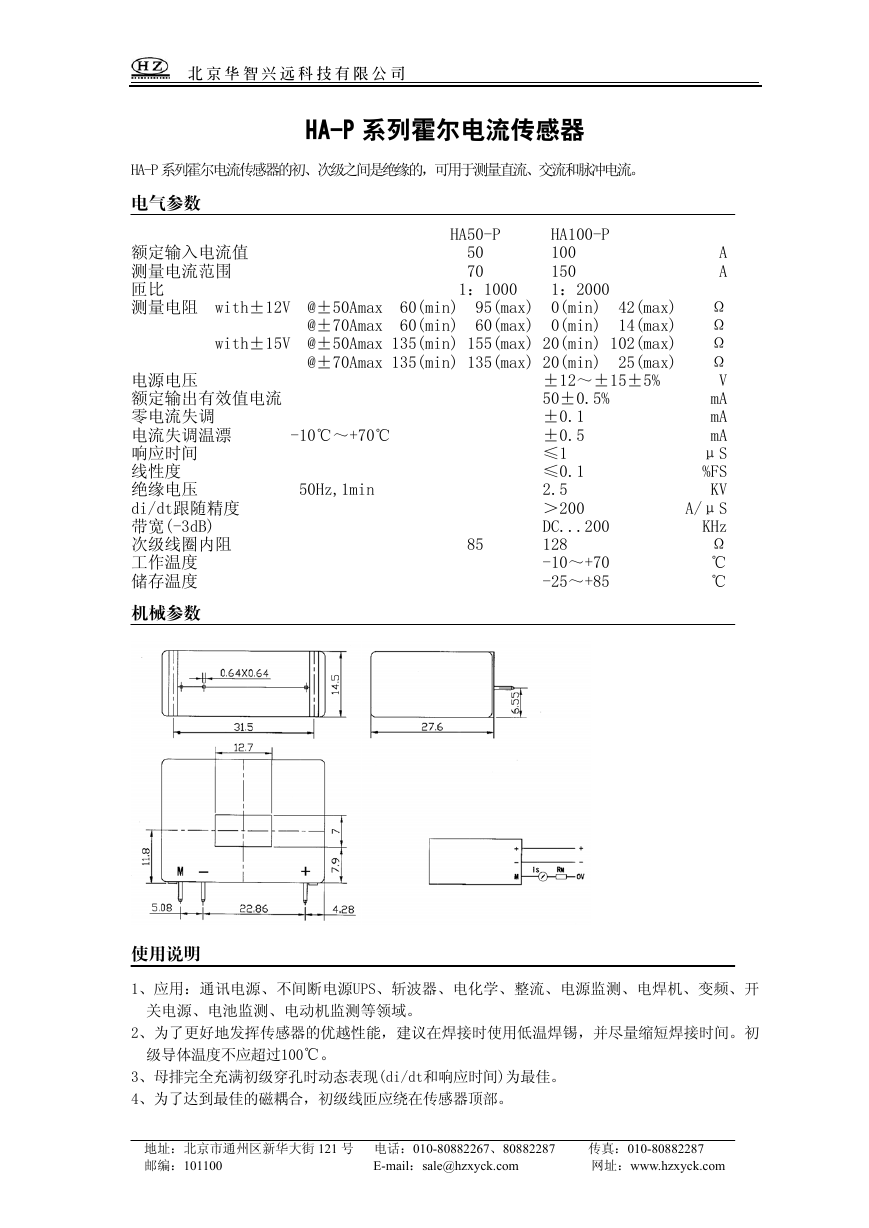 HA50-P(传感器资料).pdf
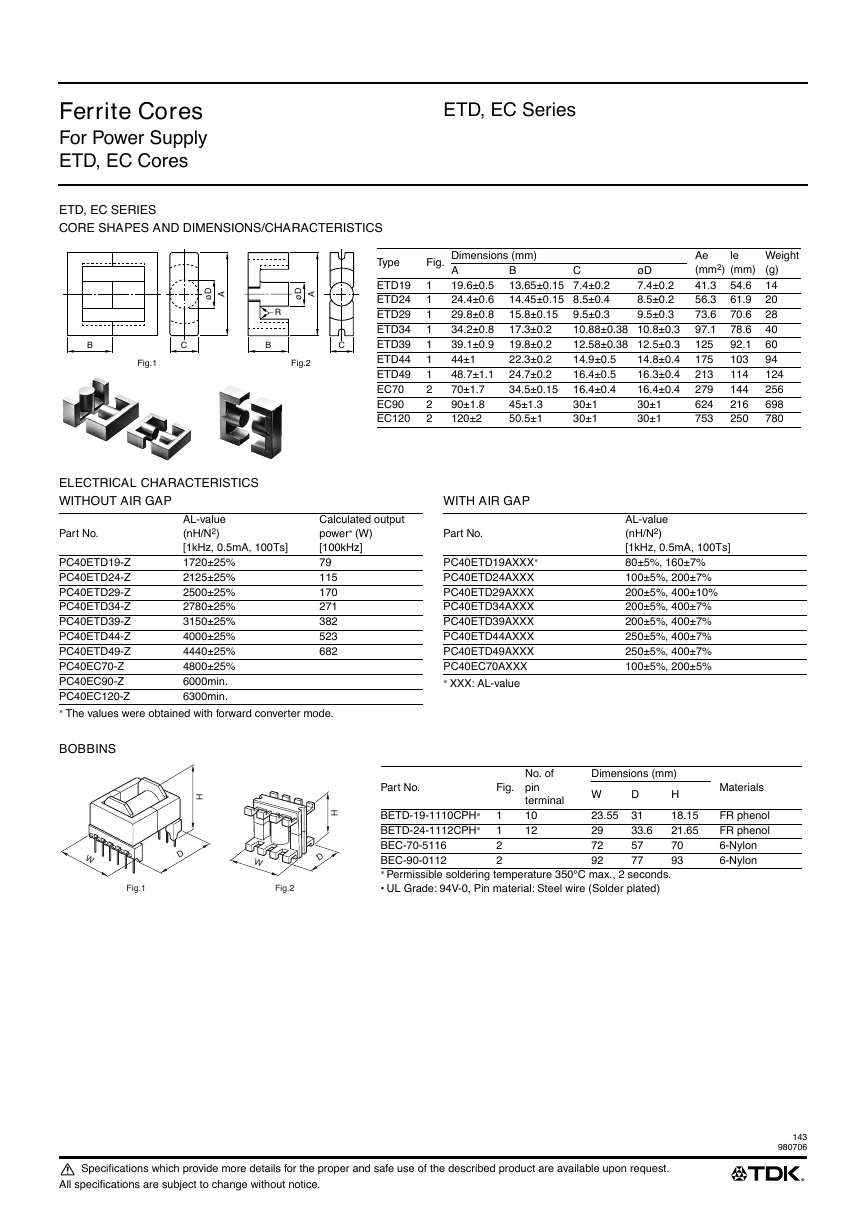 ETD-core(TDK磁芯资料).pdf