Left-Handed Metamaterial Design Using Ansoft
Designer and HFSS
by
Anthony Lai
Ansoft Corporation
Draft Copy
August 2007
�
Abstract
This paper provides a design guide for left-handed metamaterials using Ansoft Designer (Method
of Moments) and Ansoft HFSS (Finite Element Method). Detailed discussion about the de-
sign of the left-handed metamaterial unit-cells along with detailed setup for analysis of these
unit-cells in Ansoft Designer and HFSS are presented. In addition, a leaky-wave antenna and
a negative refractive index flat lens based on the analyzed left-handed unit-cells are simulated
in Designer and HFSS.
In Chapter 1, the concept of metamaterials is explained and the following questions are ex-
amined: “What are left-handed metamaterials?,” “Why are left-handed metamaterials impor-
tant?,” and “How are left-handed metamaterials realized?”
Chapter 2 provides a design guide for a one-dimensional, dominant-mode leaky-wave antenna
based on the left-handed metamaterial’s unique dispersion characteristics. This chapter begins
with a brief introduction on leaky-wave antennas and discusses the advantages of a left-handed
metamaterial implementation over a conventional implementation of the antenna. The chapter
continues with the design of a dominant-mode leaky-wave antenna using Ansoft Designer. The
analysis of the required one-dimensional left-handed metamaterial unit-cell based on microstrip
technology is presented in detail; unit-cell setup, analysis options, dispersion diagram genera-
tion, and Bloch impedance diagram generation using Ansoft Designer are outlined. Next, the
designed unit-cell is cascaded to form a leaky-wave antenna. S-parameter and far-field patterns
are generated using Ansoft Designer to verify the dominant mode backfire to endfire frequency
scanning capability of the realized antenna.
Chapter 3 deals with the analysis and design of two-dimensional left-handed metamaterials. A
negative refractive index flat lens is realized in Ansoft HFSS based on the Sievenpiper mush-
room unit-cell. First, the two-dimensional unit-cell is discussed and its dispersion diagram is
generated using two approaches; driven mode like Chapter 1 and eigenmode solver provided
in Ansoft HFSS. The dispersion diagram is used to characterize the refractive index of the
left-handed metamaterial and to determine the operational frequency for the lens application.
Then, the unit-cell is cascaded in two-dimensions in order to form a bulk left-handed metama-
terial. The HFSS setup for the lens simulation is discussed; field plots are used to confirm the
negative refraction in the lens. In addition, the HFSS field calculator is used to plot the phase
of the electric field in the lens.
�
Contents
1 Left-Handed Metamaterials
1.1 What Are Left-Handed Metamaterials?
. . . . . . . . . . . . . . . . . . . . . .
1.1.1 Backward Waves . . . . . . . . . . . . . . . . . . . . . . . . . . . . . . .
1.1.2 Negative Refractive Index . . . . . . . . . . . . . . . . . . . . . . . . . .
1.1.3 Frequency Dispersion . . . . . . . . . . . . . . . . . . . . . . . . . . . .
1.2 Why Are Left-Handed Metamaterials Important? . . . . . . . . . . . . . . . . .
1.3 How Are Left-Handed Metamaterials Realized? . . . . . . . . . . . . . . . . . .
1.3.1 Transmission Line Approach . . . . . . . . . . . . . . . . . . . . . . . .
1.3.2 Composite Right/Left-Handed Transmission Line . . . . . . . . . . . . .
1.4 Physical Realization and Analysis: Dispersion and Bloch Impedance Diagrams
1.4.1 Dispersion Diagram . . . . . . . . . . . . . . . . . . . . . . . . . . . . .
1.4.2 Bloch Impedance Diagram . . . . . . . . . . . . . . . . . . . . . . . . . .
1.5 Summary . . . . . . . . . . . . . . . . . . . . . . . . . . . . . . . . . . . . . . .
2 Ansoft Designer: Dominant-Mode Leaky-Wave Antenna
2.1
2.2 One-Dimensional CRLH Unit-Cell
Introduction . . . . . . . . . . . . . . . . . . . . . . . . . . . . . . . . . . . . . .
. . . . . . . . . . . . . . . . . . . . . . . . .
2.2.1 Design Guidelines - Initial Parameter Values
. . . . . . . . . . . . . . .
2.2.2 Dispersion Diagram Extraction . . . . . . . . . . . . . . . . . . . . . . .
2.2.3
1st Variation . . . . . . . . . . . . . . . . . . . . . . . . . . . . . . . . .
2.2.4
2nd Variation . . . . . . . . . . . . . . . . . . . . . . . . . . . . . . . . .
2.2.5 Final Variation . . . . . . . . . . . . . . . . . . . . . . . . . . . . . . . .
2.2.6 Bloch Impedance Extraction . . . . . . . . . . . . . . . . . . . . . . . .
2.3 Leaky-Wave Antenna Design . . . . . . . . . . . . . . . . . . . . . . . . . . . .
2.3.1 Feed Network Design . . . . . . . . . . . . . . . . . . . . . . . . . . . . .
2.3.2 Ansoft Designer Analysis
. . . . . . . . . . . . . . . . . . . . . . . . . .
S-Parameter and Far-Field Results . . . . . . . . . . . . . . . . . . . . .
2.3.3
2.4 Summary . . . . . . . . . . . . . . . . . . . . . . . . . . . . . . . . . . . . . . .
3 Ansoft HFSS: Negative Refractive Flat Lens
3.1
3.2 Two-Dimensional CRLH Unit-Cell
Introduction . . . . . . . . . . . . . . . . . . . . . . . . . . . . . . . . . . . . . .
. . . . . . . . . . . . . . . . . . . . . . . . .
3.2.1 Design: 1st Order Approximation . . . . . . . . . . . . . . . . . . . . . .
3.2.2 Design: Driven Mode Dispersion Diagram . . . . . . . . . . . . . . . . .
3.2.3 Verification: Eigenmode Dispersion Diagram . . . . . . . . . . . . . . .
Eigenmode Solver Setup . . . . . . . . . . . . . . . . . . . . . . . . . . .
Linked Boundary Conditions
. . . . . . . . . . . . . . . . . . . . . . . .
Eigenmode Analysis Setup . . . . . . . . . . . . . . . . . . . . . . . . . .
Dependent Solve Setup . . . . . . . . . . . . . . . . . . . . . . . . . . .
3
3
4
4
5
5
6
6
8
9
10
10
11
15
15
16
17
18
22
24
24
25
26
26
27
28
32
34
34
36
36
37
39
39
40
42
43
1
�
CONTENTS
Driven Mode versus Eigen Mode Dispersion Diagram . . . . . . . . . . .
3.3 Flat Lens Simulation . . . . . . . . . . . . . . . . . . . . . . . . . . . . . . . . .
3.3.1 Phase Matching Condition . . . . . . . . . . . . . . . . . . . . . . . . .
3.3.2 HFSS Model Setup . . . . . . . . . . . . . . . . . . . . . . . . . . . . . .
3.3.3 Analysis and Results . . . . . . . . . . . . . . . . . . . . . . . . . . . . .
3.4 Summary . . . . . . . . . . . . . . . . . . . . . . . . . . . . . . . . . . . . . . .
2
46
48
48
48
50
52
�
Chapter 1
Left-Handed Metamaterials
1.1 What Are Left-Handed Metamaterials?
Electromagnetic metamaterials are effectively homogeneous artificial structures engineered
to provide electromagnetic properties not readily observable in nature. Effectively homogeneous
means that scattering/diffraction is a minor/non-existent effect for a propagating wave in a
metamaterial; lattice constants of the metamaterial are much smaller than the electromagnetic
wave. So what kind of unique electromagnetic properties can metamaterials provide? First,
lets define what we mean by electromagnetic properties. Electromagentic properties are the
effect a material has on the electric and magnetic field of a wave, which is determined by the
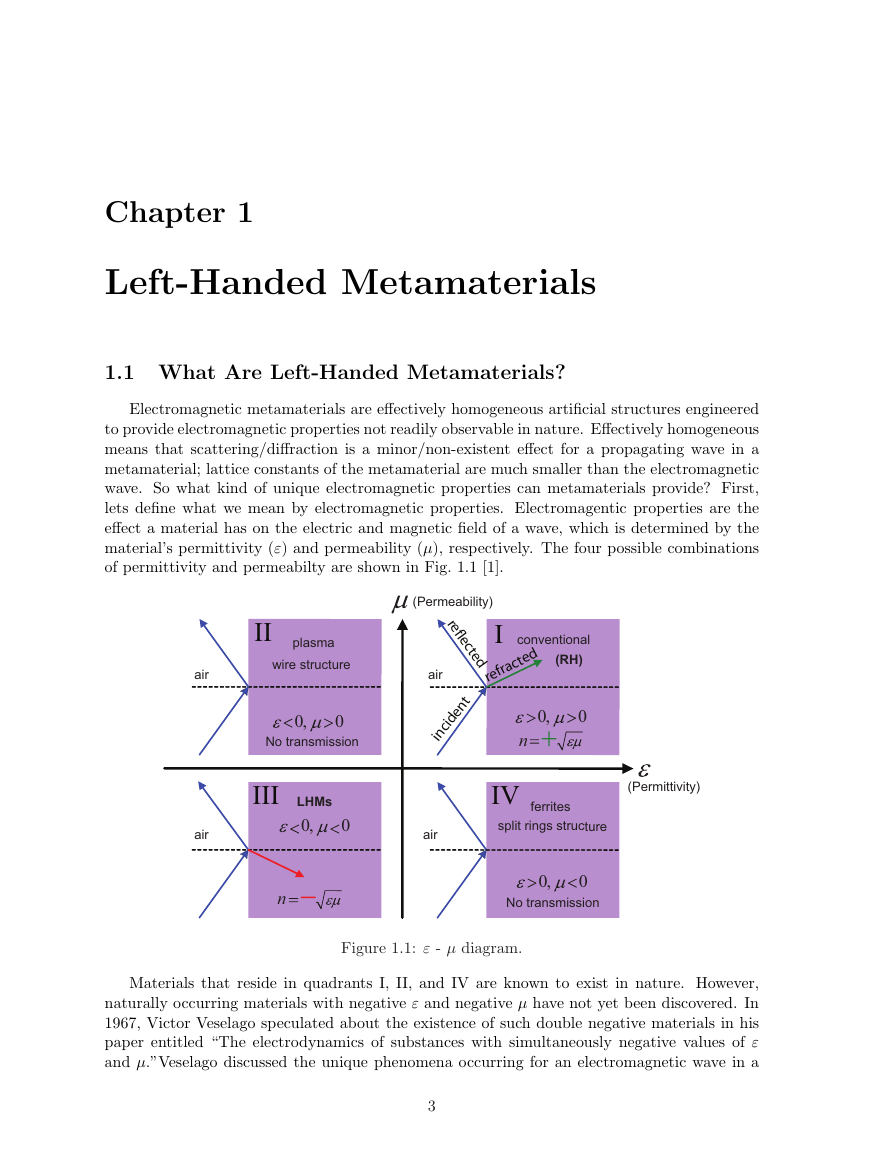
material’s permittivity (ε) and permeability (µ), respectively. The four possible combinations
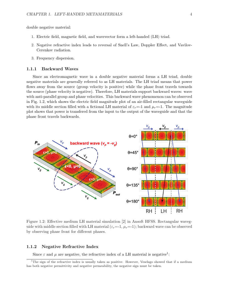
of permittivity and permeabilty are shown in Fig. 1.1 [1].
Figure 1.1: ε - µ diagram.
Materials that reside in quadrants I, II, and IV are known to exist in nature. However,
naturally occurring materials with negative ε and negative µ have not yet been discovered. In
1967, Victor Veselago speculated about the existence of such double negative materials in his
paper entitled “The electrodynamics of substances with simultaneously negative values of ε
and µ.”Veselago discussed the unique phenomena occurring for an electromagnetic wave in a
3
conventionalplasmawire structure split rings structureferritesLHMs0,0n0,00,00,0No transmissionNo transmissionn(RH)airairairair(Permittivity)(Permeability)IIIIIIIVincidentrefractedre ected�
CHAPTER 1. LEFT-HANDED METAMATERIALS
4
double negative material:
1. Electric field, magnetic field, and wavevector form a left-handed (LH) triad.
2. Negative refractive index leads to reversal of Snell’s Law, Doppler Effect, and Vavilov-
Cerenkov radiation.
3. Frequency dispersion.
1.1.1 Backward Waves
Since an electromagnetic wave in a double negative material forms a LH triad, double
negative materials are generally referred to as LH materials. The LH triad means that power
flows away from the source (group velocity is positive) while the phase front travels towards
the source (phase velocity is negative). Therefore, LH materials support backward waves: wave
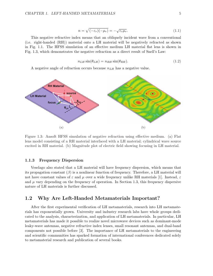
with anti-parallel group and phase velocities. This backward wave phenomenon can be observed
in Fig. 1.2, which shows the electric field magnitude plot of an air-filled rectangular waveguide
with its middle section filled with a fictional LH material of εr=-1 and µr=-1. The magnitude
plot shows that power is transfered from the input to the output of the waveguide and that the
phase front travels backwards.
Figure 1.2: Effective medium LH material simulation [2] in Ansoft HFSS. Rectangular waveg-
uide with middle section filled with LH material (εr=-1, µr=-1); backward wave can be observed
by observing phase front for different phases.
1.1.2 Negative Refractive Index
Since ε and µ are negative, the refractive index of a LH material is negative1:
1The sign of the refractive index is usually taken as positive. However, Veselago showed that if a medium
has both negative permittivity and negative permeability, the negative sign must be taken.
vpvpvpPinPoutbackward wave (vp= -vg)ε<0, μ<0ε>0, μ>0ε>0, μ>0vpvpvpvgvgvgθ=0°θ=45°θ=90°θ=135°θ=180°vpvpvpPinPoutbackward wave (vp= -vg)ε<0, μ<0ε>0, μ>0ε>0, μ>0vpvpvpvgvgvgθ=0°θ=45°θ=90°θ=135°θ=180°RHLHRH�
CHAPTER 1. LEFT-HANDED METAMATERIALS
(−εr)(−µr) = −√
εrµr.
n =
5
(1.1)
This negative refractive index means that an obliquely incident wave from a conventional
(i.e. right-handed (RH)) material onto a LH material will be negatively refracted as shown
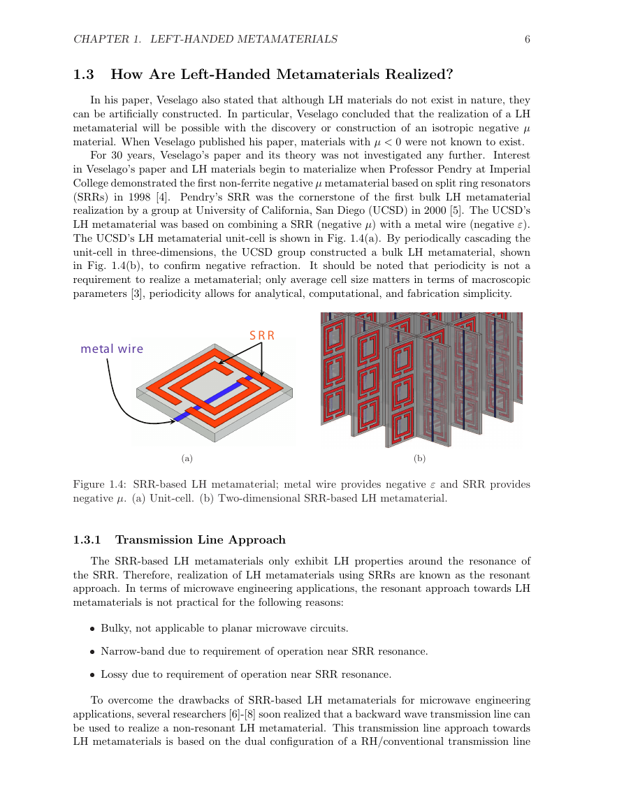
in Fig. 1.1. The HFSS simulation of an effective medium LH material flat lens is shown in
Fig. 1.3, which demonstrates the negative refraction as a direct result of Snell’s Law:
A negative angle of refraction occurs because nLH has a negative value.
nLH sin(θLH) = nRH sin(θRH).
(1.2)
(a)
(b)
Figure 1.3: Ansoft HFSS simulation of negative refraction using effective medium. (a) Flat
lens model consisting of a RH material interfaced with a LH material; cylindrical wave source
excited in RH material. (b) Magnitude plot of electric field showing focusing in LH material.
1.1.3 Frequency Dispersion
Veselago also stated that a LH material will have frequency dispersion, which means that
its propagation constant (β) is a nonlinear function of frequency. Therefore, a LH material will
not have constant values of ε and µ over a wide frequency unlike RH materials [1]. Instead, ε
and µ vary depending on the frequency of operation. In Section 1.3, this frequency dispersive
nature of LH materials is further discussed.
1.2 Why Are Left-Handed Metamaterials Important?
After the first experimental verification of LH metamaterials, research into LH metamate-
rials has exponentially grown. University and industry research labs have whole groups dedi-
cated to the analysis, characterization, and application of LH metamaterials. In particular, LH
metamaterials has made it possible to realize novel microwave devices such as dominant-mode
leaky-wave antennas, negative refractive index lenses, small resonant antennas, and dual-band
components not possible before [3]. The importance of LH metamaterials to the engineering
and scientific communities has sparked formation of international conferences dedicated solely
to metamaterial research and publication of several books.
θRHθLHsourcefocusRH MaterialLH MaterialθRHθLHsourcefocusRH MaterialLH Material�
CHAPTER 1. LEFT-HANDED METAMATERIALS
6
1.3 How Are Left-Handed Metamaterials Realized?
In his paper, Veselago also stated that although LH materials do not exist in nature, they
can be artificially constructed. In particular, Veselago concluded that the realization of a LH
metamaterial will be possible with the discovery or construction of an isotropic negative µ
material. When Veselago published his paper, materials with µ < 0 were not known to exist.
For 30 years, Veselago’s paper and its theory was not investigated any further. Interest
in Veselago’s paper and LH materials begin to materialize when Professor Pendry at Imperial
College demonstrated the first non-ferrite negative µ metamaterial based on split ring resonators
(SRRs) in 1998 [4]. Pendry’s SRR was the cornerstone of the first bulk LH metamaterial
realization by a group at University of California, San Diego (UCSD) in 2000 [5]. The UCSD’s
LH metamaterial was based on combining a SRR (negative µ) with a metal wire (negative ε).
The UCSD’s LH metamaterial unit-cell is shown in Fig. 1.4(a). By periodically cascading the
unit-cell in three-dimensions, the UCSD group constructed a bulk LH metamaterial, shown
in Fig. 1.4(b), to confirm negative refraction.
It should be noted that periodicity is not a
requirement to realize a metamaterial; only average cell size matters in terms of macroscopic
parameters [3], periodicity allows for analytical, computational, and fabrication simplicity.
(a)
(b)
Figure 1.4: SRR-based LH metamaterial; metal wire provides negative ε and SRR provides
negative µ. (a) Unit-cell. (b) Two-dimensional SRR-based LH metamaterial.
1.3.1 Transmission Line Approach
The SRR-based LH metamaterials only exhibit LH properties around the resonance of
the SRR. Therefore, realization of LH metamaterials using SRRs are known as the resonant
approach. In terms of microwave engineering applications, the resonant approach towards LH
metamaterials is not practical for the following reasons:
X Bulky, not applicable to planar microwave circuits.
X Narrow-band due to requirement of operation near SRR resonance.
X Lossy due to requirement of operation near SRR resonance.
To overcome the drawbacks of SRR-based LH metamaterials for microwave engineering
applications, several researchers [6]-[8] soon realized that a backward wave transmission line can
be used to realize a non-resonant LH metamaterial. This transmission line approach towards
LH metamaterials is based on the dual configuration of a RH/conventional transmission line
SRR metal wire �



 2023年江西萍乡中考道德与法治真题及答案.doc
 2012年重庆南川中考生物真题及答案.doc
 2013年江西师范大学地理学综合及文艺理论基础考研真题.doc
 2020年四川甘孜小升初语文真题及答案I卷.doc
 2020年注册岩土工程师专业基础考试真题及答案.doc
 2023-2024学年福建省厦门市九年级上学期数学月考试题及答案.doc
 2021-2022学年辽宁省沈阳市大东区九年级上学期语文期末试题及答案.doc
 2022-2023学年北京东城区初三第一学期物理期末试卷及答案.doc
 2018上半年江西教师资格初中地理学科知识与教学能力真题及答案.doc
 2012年河北国家公务员申论考试真题及答案-省级.doc
 2020-2021学年江苏省扬州市江都区邵樊片九年级上学期数学第一次质量检测试题及答案.doc
 2022下半年黑龙江教师资格证中学综合素质真题及答案.doc