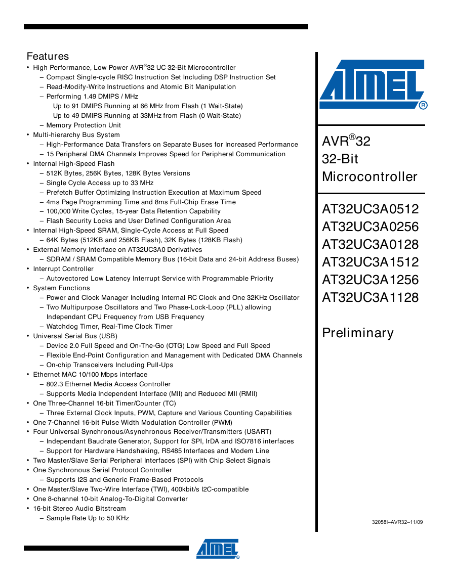
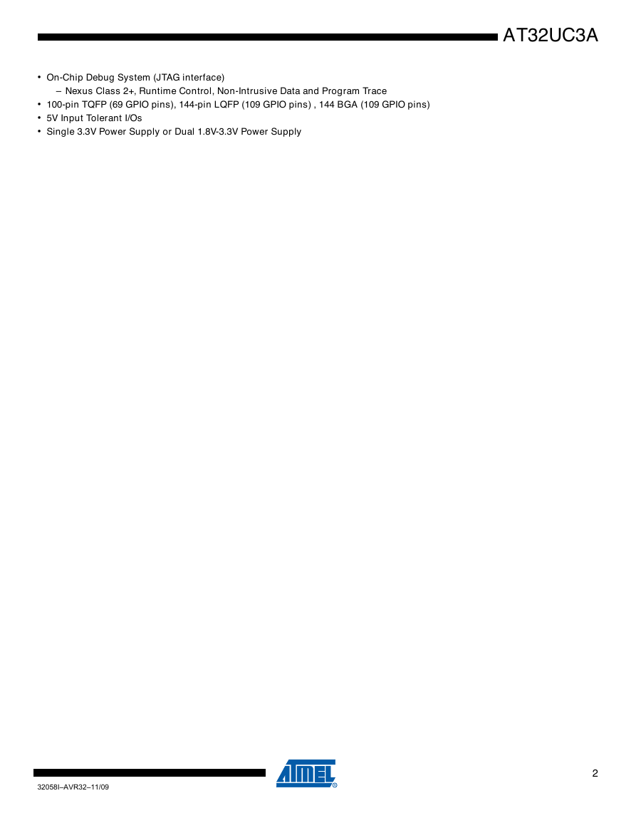
Features
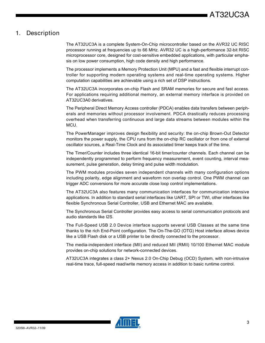
1. Description
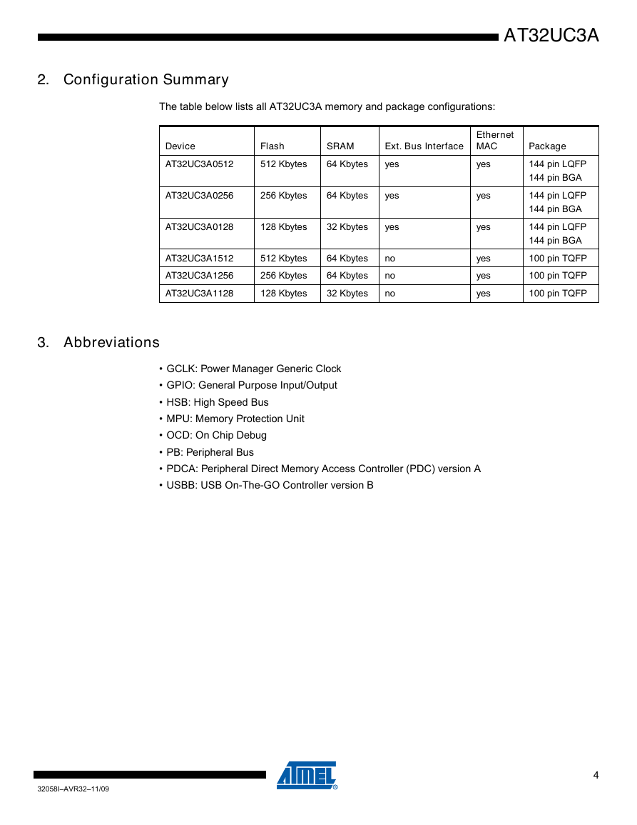
2. Configuration Summary
3. Abbreviations
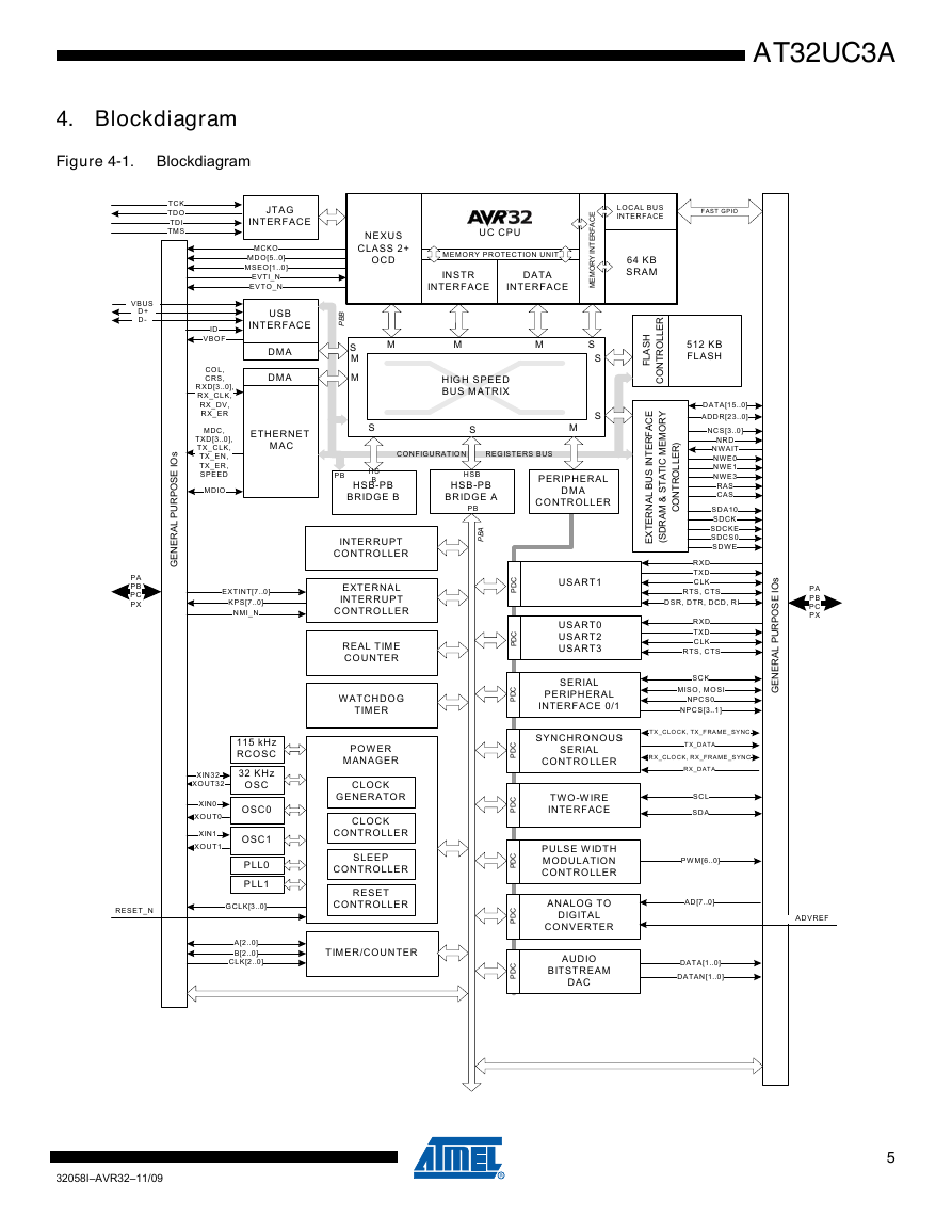
4. Blockdiagram
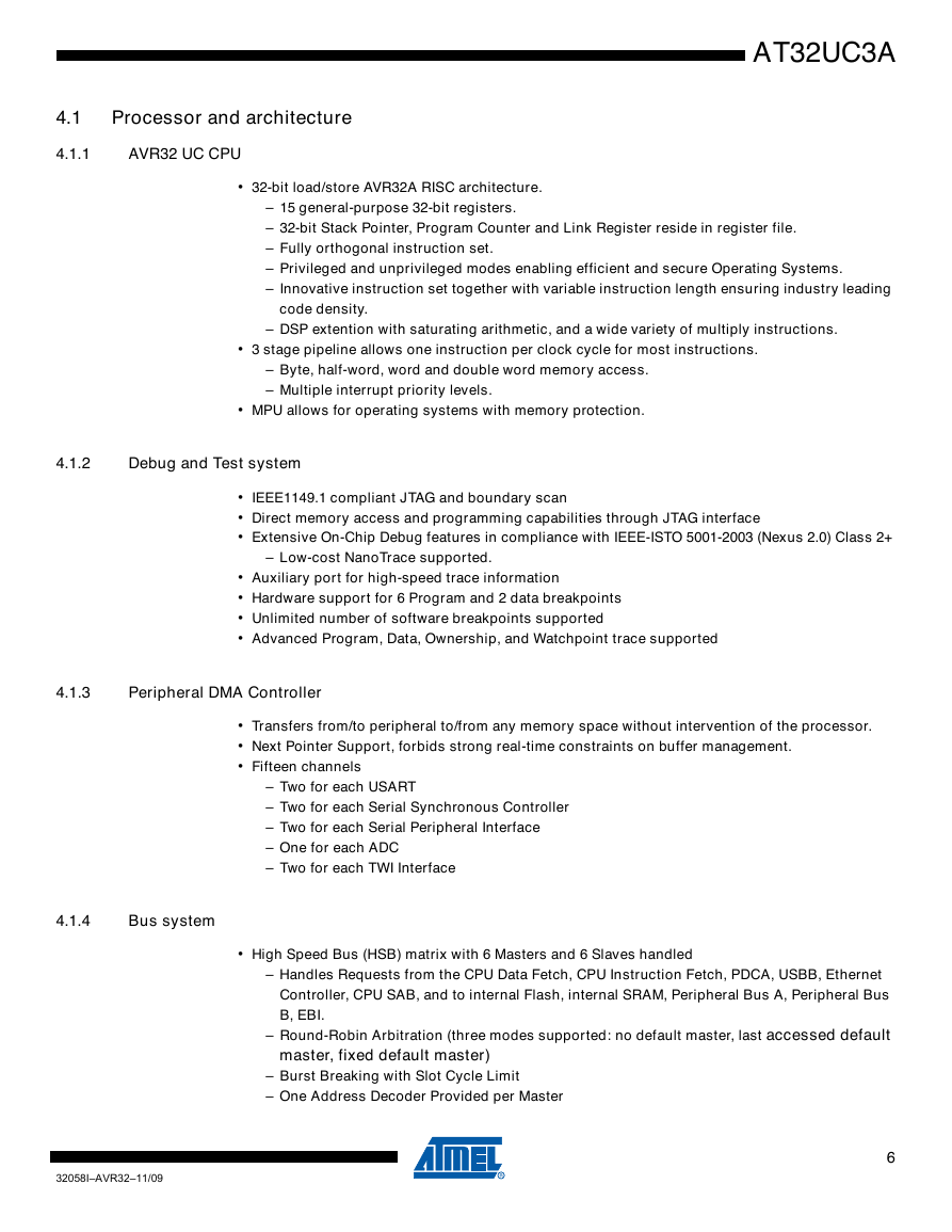
4.1 Processor and architecture
4.1.1 AVR32 UC CPU
4.1.2 Debug and Test system
4.1.3 Peripheral DMA Controller
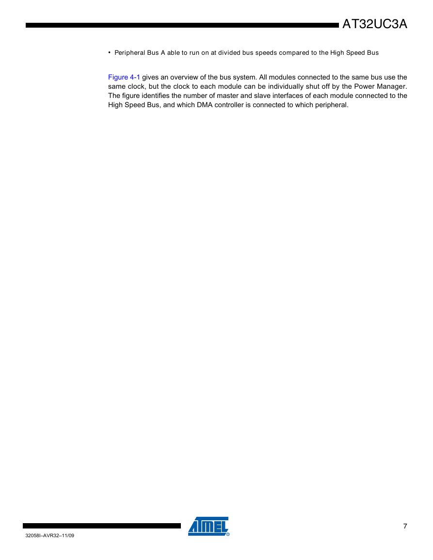
4.1.4 Bus system
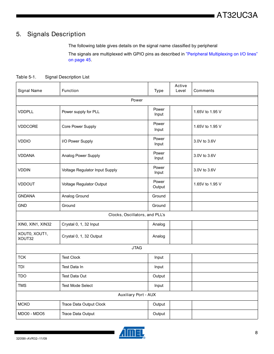
5. Signals Description
6. Power Considerations
6.1 Power Supplies
6.2 Voltage Regulator
6.2.1 Single Power Supply
6.2.2 Dual Power Supply
6.3 Analog-to-Digital Converter (A.D.C) reference.
7. Package and Pinout
8. I/O Line Considerations
8.1 JTAG pins
8.2 RESET_N pin
8.3 TWI pins
8.4 GPIO pins
9. Processor and Architecture
9.1 AVR32 Architecture
9.2 The AVR32UC CPU
9.2.1 Pipeline Overview
9.2.2 AVR32A Microarchitecture Compliance
9.2.3 Java Support
9.2.4 Memory protection
9.2.5 Unaligned reference handling
9.2.6 Unimplemented instructions
9.2.7 CPU and Architecture revision
9.3 Programming Model
9.3.1 Register file configuration
9.3.2 Status register configuration
9.3.3 Processor States
9.3.3.1 Normal RISC State
9.3.3.2 Debug State
9.3.4 System registers
9.4 Exceptions and Interrupts
9.4.1 System stack issues
9.4.2 Exceptions and interrupt requests
9.4.3 Supervisor calls
9.4.4 Debug requests
9.4.5 Entry points for events
10. Memories
10.1 Embedded Memories
10.2 Physical Memory Map
10.3 Bus Matrix Connections
11. Fuses Settings
11.1 Flash General Purpose Fuse Register (FGPFRLO)
11.2 Default Fuse Value
12. Peripherals
12.1 Peripheral address map
12.2 CPU Local Bus Mapping
12.3 Interrupt Request Signal Map
12.4 Clock Connections
12.4.1 Timer/Counters
12.4.2 USARTs
12.4.3 SPIs
12.5 Nexus OCD AUX port connections
12.6 PDC handshake signals
12.7 Peripheral Multiplexing on I/O lines
12.8 Oscillator Pinout
12.9 USART Configuration
12.10 GPIO
12.11 Peripheral overview
12.11.1 External Bus Interface
12.11.2 Static Memory Controller
12.11.3 SDRAM Controller
12.11.4 USB Controller
12.11.5 Serial Peripheral Interface
12.11.6 Two-wire Interface
12.11.7 USART
12.11.8 Serial Synchronous Controller
12.11.9 Timer Counter
12.11.10 Pulse Width Modulation Controller
12.11.11 Ethernet 10/100 MAC
12.11.12 Audio Bitstream DAC
13. Power Manager (PM)
13.1 Features
13.2 Description
13.3 Block Diagram
13.4 Product Dependencies
13.4.1 I/O Lines
13.4.2 Interrupt
13.4.3 Clock implementation
13.5 Functional Description
13.5.1 Slow clock
13.5.2 Oscillator 0 and 1 operation
13.5.3 32 KHz oscillator operation
13.5.4 PLL operation
13.5.4.1 Enabling the PLL
13.5.5 Synchronous clocks
13.5.5.1 Selecting PLL or oscillator for the main clock
13.5.5.2 Selecting synchronous clock division ratio
13.5.5.3 Clock Ready flag
13.5.6 Peripheral clock masking
13.5.6.1 Cautionary note
13.5.6.2 Mask Ready flag
13.5.7 Sleep modes
13.5.7.1 Entering and exiting sleep modes
13.5.7.2 Supported sleep modes
13.5.7.3 Precautions when entering sleep mode
13.5.7.4 Wake up
13.5.8 Generic clocks
13.5.8.1 Enabling a generic clock
13.5.8.2 Disabling a generic clock
13.5.8.3 Changing clock frequency
13.5.8.4 Generic clock implementation
13.5.9 Divided PB clocks
13.5.10 Debug operation
13.5.11 Reset Controller
13.5.11.1 Power-On Detector
13.5.11.2 Brown-Out Detector
13.5.11.3 External Reset
13.5.12 Calibration registers
13.6 User Interface
13.6.1 Main Clock Control
13.6.2 Clock Select
13.6.3 Clock Mask
13.6.4 PLL Control
13.6.5 PM Oscillator 0/1 Control
13.6.6 PM 32 KHz Oscillator Control Register
13.6.7 Interrupt Enable/Disable/Mask/Status/Clear
13.6.8 Power and Oscillators Status
13.6.9 Generic Clock Control
13.6.10 Reset Cause
13.6.11 BOD Control
13.6.12 RC Oscillator Calibration
13.6.13 Bandgap Calibration
13.6.14 PM Voltage Regulator Calibration Register
13.6.15 General Purpose Low-power register 0/1
14. Real Time Counter (RTC)
14.1 Features
14.2 Description
14.3 Block Diagram
14.4 Product Dependencies
14.4.1 Power Management
14.4.2 Interrupt
14.4.3 Debug Operation
14.4.4 Clocks
14.5 Functional Description
14.5.1 RTC operation
14.5.1.1 Source clock
14.5.1.2 Counter operation
14.5.1.3 RTC Interrupt
14.5.1.4 RTC wakeup
14.5.1.5 Busy bit
14.6 User Interface
14.6.1 RTC Control
14.6.2 RTC Value
14.6.3 RTC Top
14.6.4 RTC Interrupt Enable/Disable/Mask/Status/Clear
15. Watchdog Timer (WDT)
15.1 Features
15.2 Description
15.3 Block Diagram
15.4 Product Dependencies
15.4.1 Power Management
15.4.2 Debug Operation
15.4.3 Clocks
15.5 Functional Description
15.6 User Interface
15.6.1 WDT Control
15.6.2 WDT Clear
16. Interrupt Controller (INTC)
16.1 Description
16.2 Block Diagram
16.3 Operation
16.3.1 Non maskable interrupts
16.3.2 CPU response
16.3.3 Clearing an interrupt request
16.4 User Interface
16.4.1 Memory Map
16.4.2 Interrupt Request Map
16.4.3 Interrupt Request Registers
16.4.4 Interrupt Priority Registers
16.4.5 Interrupt Cause Registers
17. External Interrupts Controller (EIC)
17.1 Features
17.2 Description
17.3 Block Diagram
17.4 Product Dependencies
17.4.1 I/O Lines
17.4.2 Power Management
17.4.3 Interrupt
17.5 Functional Description
17.5.1 External Interrupts
17.5.1.1 Synchronization of external interrupts
17.5.1.2 Wakeup
17.5.2 Non-Maskable Interrupt
17.5.3 Keypad scan support
17.6 User Interface
17.6.1 EIC Interrupt Enable/Disable/Mask/Status/Clear
17.6.2 External Interrupt Mode/Edge/Level/Filter/Async
17.6.3 External Interrupt Test
17.6.4 External Interrupt Scan
17.6.5 External Interrupt Enable/Disable/Control
18. Flash Controller (FLASHC)
18.1 Features
18.2 Description
18.3 Product dependencies
18.3.1 Power management
18.3.2 Interrupt
18.4 Functional description
18.4.1 Bus interfaces
18.4.2 Memory organization
18.4.3 User page
18.4.4 Read operations
18.4.5 Quick Page Read
18.4.6 Write page buffer operations
18.4.7 Writing words to a page that is not completely erased
18.5 Flash commands
18.5.1 Write/erase page operation
18.5.2 Erase All operation
18.5.3 Region lock bits
18.6 General-purpose fuse bits
18.7 Security bit
18.8 User interface
18.8.1 Address map
18.8.2 Flash Control Register (FCR)
18.8.3 Flash Command Register (FCMD)
18.8.4 Flash Status Register (FSR)
18.8.5 Flash General Purpose Fuse Register High (FGPFRHI)
18.8.6 Flash General Purpose Fuse Register Low (FGPFRLO)
19. HSB Bus Matrix (HMATRIX)
19.1 Features
19.2 Description
19.3 Memory Mapping
19.4 Special Bus Granting Mechanism
19.4.1 No Default Master
19.4.2 Last Access Master
19.4.3 Fixed Default Master
19.5 Arbitration
19.5.1 Arbitration Rules
19.5.1.1 Undefined Length Burst Arbitration
19.5.1.2 Slot Cycle Limit Arbitration
19.5.2 Round-Robin Arbitration
19.5.2.1 Round-Robin Arbitration without Default Master
19.5.2.2 Round-Robin Arbitration with Last Default Master
19.5.2.3 Round-Robin Arbitration with Fixed Default Master
19.5.3 Fixed Priority Arbitration
19.6 Slave and Master assignation
19.7 User Interface
19.7.1 Bus Matrix Master Configuration Registers
19.7.2 Bus Matrix Slave Configuration Registers
19.7.3 Bus Matrix Priority Registers A For Slaves
19.7.4 Bus Matrix Priority Registers B For Slaves
19.7.5 Bus Matrix Master Remap Control Register
19.7.6 Bus Matrix Special Function Registers
20. External Bus Interface (EBI)
20.1 Features
20.2 Description
20.3 Block Diagram
20.3.1 External Bus Interface
20.4 I/O Lines Description
20.5 Application Example
20.5.1 Hardware Interface
20.5.2 Connection Examples
20.6 Product Dependencies
20.6.1 I/O Lines
20.6.2 Power Management
20.6.3 Interrupt
20.7 Functional Description
20.7.1 Bus Multiplexing
20.7.2 Pull-up Control
20.7.3 Static Memory Controller
20.7.4 SDRAM Controller
21. Peripheral DMA Controller (PDCA)
21.1 Features
21.2 Overview
21.3 Block Diagram
21.4 Functional Description
21.4.1 Configuration
21.4.2 Memory Pointer
21.4.3 Transfer Counter
21.4.4 Reload Registers
21.4.5 Peripheral Selection
21.4.6 Transfer Size
21.4.7 Enabling and Disabling
21.4.8 Interrupts
21.4.9 Priority
21.4.10 Error Handling
21.5 User Interface
21.5.1 Memory Map Overview
21.5.2 Channel Memory Map
21.5.3 PDCA Memory Address Register
21.5.4 PDCA Peripheral Select Register
21.5.5 PDCA Transfer Counter Register
21.5.6 PDCA Memory Address Reload Register
21.5.7 PDCA Transfer Counter Reload Register
21.5.8 PDCA Control Register
21.5.9 PDCA Mode Register
21.5.10 PDCA Status Register
21.5.11 PDCA Interrupt Enable Register
21.5.12 PDCA Interrupt Disable Register
21.5.13 PDCA Interrupt Mask Register
21.5.14 PDCA Interrupt Status Register
22. General-Purpose Input/Output Controller (GPIO)
22.1 Features
22.2 Overview
22.3 Product dependencies
22.3.1 Module Configuration
22.3.2 Interrupt Lines
22.3.3 Power and Clock Management
22.4 Functional Description
22.4.1 Pull-up Resistor Control
22.4.2 I/O Line or Peripheral Function Selection
22.4.3 Peripheral Selection
22.4.4 Output Control
22.4.5 Open Drain Mode
22.4.6 Inputs
22.4.7 Interrupts
22.4.8 Input Glitch Filter
22.4.9 Interrupt Timings
22.5 General Purpose Input/Output (GPIO) User Interface
22.5.1 Access Types
22.5.2 GPIO Enable Register
22.5.3 Peripheral Mux Register 0
22.5.4 Peripheral Mux Register 1
22.5.5 Output Driver Enable Register
22.5.6 Output Value Register
22.5.7 Pin Value Register
22.5.8 Pull-up Enable Register
22.5.9 Open Drain Mode Enable Register
22.5.10 Interrupt Enable Register
22.5.11 Interrupt Mode Register 0
22.5.12 Interrupt Mode Register 1
22.5.13 Glitch Filter Enable Register
22.5.14 Interrupt Flag Register
22.6 Programming Examples
22.6.1 8-bit LED-Chaser
22.6.2 Configuration of USART pins
23. Serial Peripheral Interface (SPI)
23.1 Features
23.2 Description
23.3 Block Diagram
23.4 Application Block Diagram
23.5 Signal Description
23.6 Product Dependencies
23.6.1 I/O Lines
23.6.2 Power Management
23.6.3 Interrupt
23.7 Functional Description
23.7.1 Modes of Operation
23.7.2 Data Transfer
23.7.3 Master Mode Operations
23.7.3.1 Master Mode Block Diagram
23.7.3.2 Master Mode Flow Diagram
23.7.3.3 Clock Generation
23.7.3.4 Transfer Delays
23.7.3.5 Peripheral Selection
23.7.3.6 Peripheral Chip Select Decoding
23.7.3.7 Peripheral Deselection
23.7.3.8 Mode Fault Detection
23.7.4 SPI Slave Mode
23.8 Serial Peripheral Interface (SPI) User Interface
23.8.1 SPI Control Register
23.8.2 SPI Mode Register
23.8.3 SPI Receive Data Register
23.8.4 SPI Transmit Data Register
23.8.5 SPI Status Register
23.8.6 SPI Interrupt Enable Register
23.8.7 SPI Interrupt Disable Register
23.8.8 SPI Interrupt Mask Register
23.8.9 SPI Chip Select Register
24. Two-Wire Interface (TWI)
24.1 Features
24.2 Overview
24.3 List of Abbreviations
24.4 Block Diagram
24.5 Application Block Diagram
24.6 I/O Lines Description
24.7 Product Dependencies
24.7.1 I/O Lines
24.7.2 Power Management
24.7.3 Interrupt
24.8 Functional Description
24.8.1 Transfer Format
24.9 Modes of Operation
24.10 Master Mode
24.10.1 Definition
24.10.2 Application Block Diagram
24.10.3 Programming Master Mode
24.10.4 Master Transmitter Mode
24.10.5 Master Receiver Mode
24.10.6 Internal Address
24.10.6.1 7-bit Slave Addressing
24.10.6.2 10-bit Slave Addressing
24.11 Internal Address Usage Using the Peripheral DMA Controller (PDC)
24.11.1 Data Transmit with the PDC
24.11.2 Data Receive with the PDC
24.11.3 Read-write Flowcharts
24.12 Multi-master Mode
24.12.1 Definition
24.12.2 Different Multi-master Modes
24.12.2.1 TWI as Master Only
24.12.2.2 TWI as Master or Slave
24.13 Slave Mode
24.13.1 Definition
24.13.2 Application Block Diagram
24.13.3 Programming Slave Mode
24.13.4 Receiving Data
24.13.4.1 Read Sequence
24.13.4.2 Write Sequence
24.13.4.3 Clock Synchronization Sequence
24.13.4.4 General Call
24.13.4.5 PDC
24.13.5 Data Transfer
24.13.5.1 Read Operation
24.13.5.2 Write Operation
24.13.5.3 General Call
24.13.6 Clock Synchronization
24.13.6.1 Clock Synchronization in Read Mode
24.13.6.2 Clock Synchronization in Write Mode
24.13.7 Reversal after a Repeated Start
24.13.7.1 Reversal of Read to Write
24.13.7.2 Reversal of Write to Read
24.13.8 Read Write Flowcharts
24.14 Two-wire Interface (TWI) User Interface
24.14.1 Register Mapping
24.14.2 TWI Control Register
24.14.3 TWI Master Mode Register
24.14.4 TWI Slave Mode Register
24.14.5 TWI Internal Address Register
24.14.6 TWI Clock Waveform Generator Register
24.14.7 TWI Status Register
24.14.8 TWI Interrupt Enable Register
24.14.9 TWI Interrupt Disable Register
24.14.10 TWI Interrupt Mask Register
24.14.11 TWI Receive Holding Register
24.14.12 TWI Transmit Holding Register
25. Synchronous Serial Controller (SSC)
25.1 Features
25.2 Overview
25.3 Block Diagram
25.4 Application Block Diagram
25.5 I/O Lines Description
25.6 Product Dependencies
25.6.1 I/O Lines
25.6.2 Power Management
25.6.3 Interrupt
25.7 Functional Description
25.7.1 Clock Management
25.7.1.1 Clock Divider
25.7.1.2 Transmitter Clock Management
25.7.1.3 Receiver Clock Management
25.7.1.4 Serial Clock Ratio Considerations
25.7.2 Transmitter Operations
25.7.3 Receiver Operations
25.7.4 Start
25.7.5 Frame Sync
25.7.5.1 Frame Sync Data
25.7.5.2 Frame Sync Edge Detection
25.7.6 Receive Compare Modes
25.7.6.1 Compare Functions
25.7.7 Data Format
25.7.8 Loop Mode
25.7.9 Interrupt
25.8 SSC Application Examples
25.9 User Interface
25.9.1 Control Register
25.9.2 Clock Mode Register
25.9.3 Receive Clock Mode Register
25.9.4 Receive Frame Mode Register
25.9.5 Transmit Clock Mode Register
25.9.6 Transmit Frame Mode Register
25.9.7 SSC Receive Holding Register
25.9.8 Transmit Holding Register
25.9.9 Receive Synchronization Holding Register
25.9.10 Transmit Synchronization Holding Register
25.9.11 Receive Compare 0 Register
25.9.12 Receive Compare 1 Register
25.9.13 Status Register
25.9.14 Interrupt Enable Register
25.9.15 Interrupt Disable Register
25.9.16 Interrupt Mask Register
26. Universal Synchronous/Asynchronous Receiver/Transmitter (USART)
26.1 Features
26.2 Overview
26.3 Block Diagram
26.4 Application Block Diagram
26.5 I/O Lines Description
26.6 Product Dependencies
26.6.1 I/O Lines
26.6.2 Power Manager (PM)
26.6.3 Interrupt
26.7 Functional Description
26.7.1 Baud Rate Generator
26.7.1.1 Baud Rate in Asynchronous Mode
26.7.1.2 Baud Rate Calculation Example
26.7.1.3 Fractional Baud Rate in Asynchronous Mode
26.7.1.4 Baud Rate in Synchronous Mode or SPI Mode
26.7.1.5 Baud Rate in ISO 7816 Mode
26.7.2 Receiver and Transmitter Control
26.7.3 Synchronous and Asynchronous Modes
26.7.3.1 Transmitter Operations
26.7.3.2 Manchester Encoder
26.7.3.3 Drift Compensation
26.7.3.4 Asynchronous Receiver
26.7.3.5 Manchester Decoder
26.7.3.6 Radio Interface: Manchester Encoded USART Application
26.7.4 Synchronous Receiver
26.7.4.1 Receiver Operations
26.7.4.2 Parity
26.7.4.3 Multidrop Mode
26.7.4.4 Transmitter Timeguard
26.7.4.5 Receiver Time-out
26.7.4.6 Framing Error
26.7.4.7 Transmit Break
26.7.4.8 Receive Break
26.7.4.9 Hardware Handshaking
26.7.5 ISO7816 Mode
26.7.5.1 ISO7816 Mode Overview
26.7.5.2 Protocol T = 0
26.7.5.3 Receive Error Counter
26.7.5.4 Receive NACK Inhibit
26.7.5.5 Transmit Character Repetition
26.7.5.6 Disable Successive Receive NACK
26.7.5.7 Protocol T = 1
26.7.6 IrDA Mode
26.7.6.1 IrDA Modulation
26.7.6.2 IrDA Baud Rate
26.7.6.3 IrDA Demodulator
26.7.7 RS485 Mode
26.7.8 SPI Mode
26.7.8.1 Modes of Operation
26.7.8.2 Baud Rate
26.7.8.3 Data Transfer
26.7.8.4 Receiver and Transmitter Control
26.7.8.5 Character Transmission
26.7.8.6 Character Reception
26.7.8.7 Receiver Timeout
26.7.9 Test Modes
26.7.9.1 Normal Mode
26.7.9.2 Automatic Echo Mode
26.7.9.3 Local Loopback Mode
26.7.9.4 Remote Loopback Mode
26.8 Universal Synchronous/Asynchronous Receiver/Transmitter (USART) User Interface
26.8.1 Register Mapping
26.8.2 USART Control Register
26.8.3 USART Mode Register
26.8.4 USART Interrupt Enable Register
26.8.5 USART Interrupt Disable Register
26.8.6 USART Interrupt Mask Register
26.8.7 USART Channel Status Register
26.8.8 USART Receive Holding Register
26.8.9 USART Transmit Holding Register
26.8.10 USART Baud Rate Generator Register
26.8.11 USART Receiver Time-out Register
26.8.12 USART Transmitter Timeguard Register
26.8.13 USART FI DI RATIO Register
26.8.14 USART Number of Errors Register
26.8.15 USART IrDA FILTER Register
26.8.16 USART Manchester Configuration Register
26.8.17 USART Version Register
27. Static Memory Controller (SMC)
27.1 Features
27.2 Overview
27.3 Block Diagram
27.4 I/O Lines Description
27.5 Product Dependencies
27.5.1 EBI I/O Lines
27.6 Functionnal Description
27.6.1 Application Example
27.6.1.1 Hardware Interface
27.6.2 External Memory Mapping
27.6.3 Connection to External Devices
27.6.3.1 Data Bus Width
27.6.3.2 Byte Write or Byte Select Access
27.6.4 Standard Read and Write Protocols
27.6.4.1 Read Waveforms
27.6.4.2 Read Mode
27.6.4.3 Write Waveforms
27.6.4.4 NCS Waveforms
27.6.4.5 Write Mode
27.6.4.6 Coding Timing Parameters
27.6.4.7 Usage Restriction
27.6.5 Automatic Wait States
27.6.5.1 Chip Select Wait States
27.6.5.2 Early Read Wait State
27.6.5.3 Reload User Configuration Wait State
27.6.5.4 Read to Write Wait State
27.6.6 Data Float Wait States
27.6.6.1 READ_MODE
27.6.6.2 TDF Optimization Enabled (TDF_MODE = 1)
27.6.6.3 TDF Optimization Disabled (TDF_MODE = 0)
27.6.7 External Wait
27.6.7.1 Restriction
27.6.7.2 Frozen Mode
27.6.7.3 Ready Mode
27.6.7.4 NWAIT Latency and Read/write Timings
27.6.8 Slow Clock Mode
27.6.8.1 Slow Clock Mode Waveforms
27.6.8.2 Switching from (to) Slow Clock Mode to (from) Normal Mode
27.6.9 Asynchronous Page Mode
27.6.9.1 Protocol and Timings in Page Mode
27.6.9.2 Byte Access Type in Page Mode
27.6.9.3 Page Mode Restriction
27.6.9.4 Sequential and Non-sequential Accesses
27.7 User Interface
27.7.1 Setup Register
27.7.2 Pulse Register
27.7.3 Cycle Register
27.7.4 MODE Register
28. SDRAM Controller (SDRAMC)
28.1 Features
28.2 Description
28.3 Block Diagram
28.4 I/O Lines Description
28.5 Application Example
28.5.1 Hardware Interface
28.5.2 Software Interface
28.5.2.1 32-bit Memory Data Bus Width
28.5.2.2 16-bit Memory Data Bus Width
28.6 Product Dependencies
28.6.1 SDRAM Device Initialization
28.6.2 I/O Lines
28.6.3 Interrupt
28.7 Functional Description
28.7.1 SDRAM Controller Write Cycle
28.7.2 SDRAM Controller Read Cycle
28.7.3 Border Management
28.7.4 SDRAM Controller Refresh Cycles
28.7.5 Power Management
28.7.5.1 Self-refresh Mode
28.7.5.2 Low-power Mode
28.7.5.3 Deep Power-down Mode
28.8 SDRAM Controller User Interface
28.8.1 SDRAMC Mode Register
28.8.2 SDRAMC Refresh Timer Register
28.8.3 SDRAMC Configuration Register
28.8.4 SDRAMC High Speed Register
28.8.5 SDRAMC Low Power Register
28.8.6 SDRAMC Interrupt Enable Register
28.8.7 SDRAMC Interrupt Disable Register
28.8.8 SDRAMC Interrupt Mask Register
28.8.9 SDRAMC Interrupt Status Register
28.8.10 SDRAMC Memory Device Register
29. Ethernet MAC (MACB)
29.1 Features
29.2 Description
29.3 Block Diagram
29.4 Product Dependencies
29.4.1 I/O Lines
29.4.2 Power Management
29.4.3 Interrupt
29.5 Functional Description
29.5.1 Memory Interface
29.5.1.1 FIFO
29.5.1.2 Receive Buffers
29.5.1.3 Transmit Buffer
29.5.2 Transmit Block
29.5.3 Pause Frame Support
29.5.4 Receive Block
29.5.5 Address Checking Block
29.5.6 Broadcast Address
29.5.7 Hash Addressing
29.5.8 External Address Matching
29.5.9 Copy All Frames (or Promiscuous Mode)
29.5.10 Type ID Checking
29.5.11 VLAN Support
29.5.12 PHY Maintenance
29.5.13 Media Independent Interface
29.5.13.1 RMII Transmit and Receive Operation
29.6 Programming Interface
29.6.1 Initialization
29.6.1.1 Configuration
29.6.1.2 Receive Buffer List
29.6.1.3 Transmit Buffer List
29.6.1.4 Address Matching
29.6.1.5 Interrupts
29.6.1.6 Transmitting Frames
29.6.1.7 Receiving Frames
29.7 Ethernet MAC (MACB) User Interface
29.7.1 Network Control Register
29.7.2 Network Configuration Register
29.7.3 Network Status Register
29.7.4 Transmit Status Register
29.7.5 Receive Buffer Queue Pointer Register
29.7.6 Transmit Buffer Queue Pointer Register
29.7.7 Receive Status Register
29.7.8 Interrupt Status Register
29.7.9 Interrupt Enable Register
29.7.10 Interrupt Disable Register
29.7.11 Interrupt Mask Register
29.7.12 PHY Maintenance Register
29.7.13 Pause Time Register
29.7.14 Hash Register Bottom
29.7.15 Hash Register Top
29.7.16 Specific Address 1 Bottom Register
29.7.17 Specific Address 1 Top Register
29.7.18 Specific Address 2 Bottom Register
29.7.19 Specific Address 2 Top Register
29.7.20 Specific Address 3 Bottom Register
29.7.21 Specific Address 3 Top Register
29.7.22 Specific Address 4 Bottom Register
29.7.23 Specific Address 4 Top Register
29.7.24 Type ID Checking Register
29.7.25 Transmit Pause Quantum Register
29.7.26 User Input/Output Register
29.7.27 Wake-on-LAN Register
29.7.28 MACB Statistic Registers
29.7.28.1 Pause Frames Received Register
29.7.28.2 Frames Transmitted OK Register
29.7.28.3 Single Collision Frames Register
29.7.28.4 Multicollision Frames Register
29.7.28.5 Frames Received OK Register
29.7.28.6 Frames Check Sequence Errors Register
29.7.28.7 Alignment Errors Register
29.7.28.8 Deferred Transmission Frames Register
29.7.28.9 Late Collisions Register
29.7.28.10 Excessive Collisions Register
29.7.28.11 Transmit Underrun Errors Register
29.7.28.12 Carrier Sense Errors Register
29.7.28.13 Receive Resource Errors Register
29.7.28.14 Receive Overrun Errors Register
29.7.28.15 Receive Symbol Errors Register
29.7.28.16 Excessive Length Errors Register
29.7.28.17 Receive Jabbers Register
29.7.28.18 Undersize Frames Register
29.7.28.19 SQE Test Errors Register
29.7.28.20 Received Length Field Mismatch Register
29.7.28.21 Transmitted Pause Frames Register
30. USB On-The-Go Interface (USBB)
30.1 Features
30.2 Description
30.3 Block Diagram
30.4 Application Block Diagram
30.4.1 Device Mode
30.4.1.1 Bus-Powered Device
30.4.1.2 Self-Powered Device
30.4.2 Host and OTG Modes
30.5 I/O Lines Description
30.6 Product Dependencies
30.6.1 I/O Lines
30.6.2 Power Management
30.6.3 Interrupts
30.7 Functional Description
30.7.1 USB General Operation
30.7.1.1 Introduction
30.7.1.2 Power-On and Reset
30.7.1.3 Interrupts
30.7.1.4 MCU Power Modes
30.7.1.5 Speed Control
30.7.1.6 DPRAM Management
30.7.1.7 Pad Suspend
30.7.1.8 Customizing of OTG Timers
30.7.1.9 Plug-In Detection
30.7.1.10 ID Detection
30.7.2 USB Device Operation
30.7.2.1 Introduction
30.7.2.2 Power-On and Reset
30.7.2.3 USB Reset
30.7.2.4 Endpoint Reset
30.7.2.5 Endpoint Activation
30.7.2.6 Address Setup
30.7.2.7 Suspend and Wake-Up
30.7.2.8 Detach
30.7.2.9 Remote Wake-Up
30.7.2.10 STALL Request
30.7.2.11 Management of Control Endpoints
30.7.2.12 Management of IN Endpoints
30.7.2.13 Management of OUT Endpoints
30.7.2.14 Underflow
30.7.2.15 Overflow
30.7.2.16 CRC Error
30.7.2.17 Interrupts
30.7.3 USB Host Operation
30.7.3.1 Description of Pipes
30.7.3.2 Power-On and Reset
30.7.3.3 Device Detection
30.7.3.4 USB Reset
30.7.3.5 Pipe Reset
30.7.3.6 Pipe Activation
30.7.3.7 Address Setup
30.7.3.8 Remote Wake-Up
30.7.3.9 Management of Control Pipes
30.7.3.10 Management of IN Pipes
30.7.3.11 Management of OUT Pipes
30.7.3.12 CRC Error
30.7.3.13 Interrupts
30.7.4 USB DMA Operation
30.8 USB User Interface
30.8.1 USB General Registers
30.8.1.1 USB General Control Register (USBCON)
30.8.1.2 USB General Status Register (USBSTA)
30.8.1.3 USB General Status Clear Register (USBSTACLR)
30.8.1.4 USB General Status Set Register (USBSTASET)
30.8.1.5 USB IP Version Register (UVERS)
30.8.1.6 USB IP Features Register (UFEATURES)
30.8.1.7 USB IP PB Address Size Register (UADDRSIZE)
30.8.1.8 USB IP Name Register 1 (UNAME1)
30.8.1.9 USB IP Name Register 2 (UNAME2)
30.8.1.10 USB Finite State Machine Status Register (USBFSM)
30.8.2 USB Device Registers
30.8.2.1 USB Device General Control Register (UDCON)
30.8.2.2 USB Device Global Interrupt Register (UDINT)
30.8.2.3 USB Device Global Interrupt Clear Register (UDINTCLR)
30.8.2.4 USB Device Global Interrupt Set Register (UDINTSET)
30.8.2.5 USB Device Global Interrupt Enable Register (UDINTE)
30.8.2.6 USB Device Global Interrupt Enable Clear Register (UDINTECLR)
30.8.2.7 USB Device Global Interrupt Enable Set Register (UDINTESET)
30.8.2.8 USB Device Frame Number Register (UDFNUM)
30.8.2.9 USB Endpoint Enable/Reset Register (UERST)
30.8.2.10 USB Endpoint X Configuration Register (UECFGX)
30.8.2.11 USB Endpoint X Status Register (UESTAX)
30.8.2.12 USB Endpoint X Status Clear Register (UESTAXCLR)
30.8.2.13 USB Endpoint X Status Set Register (UESTAXSET)
30.8.2.14 USB Endpoint X Control Register (UECONX)
30.8.2.15 USB Endpoint X Control Clear Register (UECONXCLR)
30.8.2.16 USB Endpoint X Control Set Register (UECONXSET)
30.8.2.17 USB Device DMA Channel X Next Descriptor Address Register (UDDMAX_NEXTDESC)
30.8.2.18 USB Device DMA Channel X HSB Address Register (UDDMAX_ADDR)
30.8.2.19 USB Device DMA Channel X Control Register (UDDMAX_CONTROL)
30.8.2.20 USB Device DMA Channel X Status Register (UDDMAX_STATUS)
30.8.3 USB Host Registers
30.8.3.1 USB Host General Control Register (UHCON)
30.8.3.2 USB Host Global Interrupt Register (UHINT)
30.8.3.3 USB Host Global Interrupt Clear Register (UHINTCLR)
30.8.3.4 USB Host Global Interrupt Set Register (UHINTSET)
30.8.3.5 USB Host Global Interrupt Enable Register (UHINTE)
30.8.3.6 USB Host Global Interrupt Enable Clear Register (UHINTECLR)
30.8.3.7 USB Host Global Interrupt Enable Set Register (UHINTESET)
30.8.3.8 USB Host Frame Number Register (UHFNUM)
30.8.3.9 USB Host Frame Number Register (UHADDR1)
30.8.3.10 USB Host Frame Number Register (UHADDR2)
30.8.3.11 USB Pipe Enable/Reset Register (UPRST)
30.8.3.12 USB Pipe X Configuration Register (UPCFGX)
30.8.3.13 USB Pipe X Status Register (UPSTAX)
30.8.3.14 USB Pipe X Status Clear Register (UPSTAXCLR)
30.8.3.15 USB Pipe X Status Set Register (UPSTAXSET)
30.8.3.16 USB Pipe X Control Register (UPCONX)
30.8.3.17 USB Pipe X Control Clear Register (UPCONXCLR)
30.8.3.18 USB Pipe X Control Set Register (UPCONXSET)
30.8.3.19 USB Pipe X IN Request Register (UPINRQX)
30.8.3.20 USB Pipe X Error Register (UPERRX)
30.8.3.21 USB Host DMA Channel X Next Descriptor Address Register (UHDMAX_NEXTDESC)
30.8.3.22 USB Host DMA Channel X HSB Address Register (UHDMAX_ADDR)
30.8.3.23 USB Host DMA Channel X Control Register (UHDMAX_CONTROL)
30.8.3.24 USB Host DMA Channel X Status Register (UHDMAX_STATUS)
30.8.4 USB Pipe/Endpoint X FIFO Data Register (USB_FIFOX_DATA)
31. Timer/Counter (TC)
31.1 Features
31.2 Description
31.3 Block Diagram
31.4 Pin Name List
31.5 Product Dependencies
31.5.1 I/O Lines
31.5.2 Debug operation
31.5.3 Power Management
31.5.4 Interrupt
31.6 Functional Description
31.6.1 TC Description
31.6.1.1 16-bit Counter
31.6.1.2 Clock Selection
31.6.1.3 Clock Control
31.6.1.4 TC Operating Modes
31.6.1.5 Trigger
31.6.2 Capture Operating Mode
31.6.2.1 Capture Registers A and B
31.6.2.2 Trigger Conditions
31.6.3 Waveform Operating Mode
31.6.3.1 Waveform Selection
31.6.3.2 WAVSEL = 00
31.6.3.3 WAVSEL = 10
31.6.3.4 WAVSEL = 01
31.6.3.5 WAVSEL = 11
31.6.3.6 External Event/Trigger Conditions
31.6.3.7 Output Controller
31.7 Timer Counter (TC) User Interface
31.7.1 TC Block Control Register
31.7.2 TC Block Mode Register
31.7.3 TC Channel Control Register
31.7.4 TC Channel Mode Register: Capture Mode
31.7.5 TC Channel Mode Register: Waveform Mode
31.7.6 TC Counter Value Register
31.7.7 TC Register A
31.7.8 TC Register B
31.7.9 TC Register C
31.7.10 TC Status Register
31.7.11 TC Interrupt Enable Register
31.7.12 TC Interrupt Disable Register
31.7.13 TC Interrupt Mask Register
32. Pulse Width Modulation Controller (PWM)
32.1 Features
32.2 Description
32.3 Block Diagram
32.4 I/O Lines Description
32.5 Product Dependencies
32.5.1 I/O Lines
32.5.2 Debug operation
32.5.3 Power Management
32.5.4 Interrupt Sources
32.6 Functional Description
32.6.1 PWM Clock Generator
32.6.2 PWM Channel
32.6.2.1 Block Diagram
32.6.2.2 Waveform Properties
32.6.3 PWM Controller Operations
32.6.3.1 Initialization
32.6.3.2 Source Clock Selection Criteria
32.6.3.3 Changing the Duty Cycle or the Period
32.6.3.4 Interrupts
32.7 Pulse Width Modulation (PWM) Controller User Interface
32.7.1 Register Mapping
32.7.2 PWM Mode Register
32.7.3 PWM Enable Register
32.7.4 PWM Disable Register
32.7.5 PWM Status Register
32.7.6 PWM Interrupt Enable Register
32.7.7 PWM Interrupt Disable Register
32.7.8 PWM Interrupt Mask Register
32.7.9 PWM Interrupt Status Register
32.7.10 PWM Channel Mode Register
32.7.11 PWM Channel Duty Cycle Register
32.7.12 PWM Channel Period Register
32.7.13 PWM Channel Counter Register
32.7.14 PWM Channel Update Register
33. Analog-to-Digital Converter (ADC)
33.1 Features
33.2 Overview
33.3 Block Diagram
33.4 I/O Lines Description
33.5 Product Dependencies
33.5.1 GPIO
33.5.2 Analog Inputs
33.5.3 Power Manager
33.5.4 Interrupt Controller
33.5.5 Timer Triggers
33.5.6 Conversion Performances
33.6 Functional Description
33.6.1 Analog-to-digital Conversion
33.6.2 Conversion Reference
33.6.3 Conversion Resolution
33.6.4 Conversion Results
33.6.5 Conversion Triggers
33.6.6 Sleep Mode and Conversion Sequencer
33.6.7 ADC Timings
33.7 User Interface
33.7.1 Control Register
33.7.2 Mode Register
33.7.3 Channel Enable Register
33.7.4 Channel Disable Register
33.7.5 Channel Status Register
33.7.6 Status Register
33.7.7 Last Converted Data Register
33.7.8 Interrupt Enable Register
33.7.9 Interrupt Disable Register
33.7.10 Interrupt Mask Register
33.7.11 Channel Data Register
33.7.12 Version Register
34. Audio Bitstream DAC (ABDAC)
34.1 Features
34.2 Description
34.3 Block Diagram
34.4 Pin Name List
34.5 Product Dependencies
34.5.1 I/O Lines
34.5.2 Power Management
34.5.3 Clock Management
34.5.4 Interrupts
34.5.5 DMA
34.6 Functional Description
34.6.1 Equalization Filter
34.6.2 Interpolation filter
34.6.3 Sigma Delta Modulator
34.6.4 Data Format
34.7 Audio Bitstream DAC User Interface
34.7.1 Audio Bitstream DAC Sample Data Register
34.7.2 Audio Bitstream DAC Control Register
34.7.3 Audio Bitstream DAC Interrupt Mask Register
34.7.4 Audio Bitstream DAC Interrupt Enable Register
34.7.5 Audio Bitstream DAC Interrupt Disable Register
34.7.6 Audio Bitstream DAC Interrupt Clear Register
34.7.7 Audio Bitstream DAC Interrupt Status Register
34.8 Frequency Response
35. On-Chip Debug
35.1 Features
35.2 Overview
35.3 Block diagram
35.4 Functional description
35.4.1 JTAG-based debug features
35.4.1.1 Debug Communication Channel
35.4.1.2 Breakpoints
35.4.1.3 OCD Mode
35.4.1.4 Monitor Mode
35.4.1.5 Program Counter monitoring
35.4.2 Memory Service Unit
35.4.2.1 Cyclic Redundancy Check (CRC)
35.4.2.2 NanoTrace
35.4.3 AUX-based debug features
35.4.3.1 Trace operation
35.4.3.2 Program Trace
35.4.3.3 Data Trace
35.4.3.4 Ownership Trace
35.4.3.5 Watchpoint messages
35.4.3.6 Event In and Event Out pins
35.4.3.7 Software Quality Analysis (SQA)
36. JTAG and Boundary Scan
36.1 Features
36.2 Overview
36.3 Block diagram
36.4 I/O Lines Description
36.5 Product Dependencies
36.5.1 I/O Lines
36.6 Functional description
36.6.1 JTAG interface
36.6.2 Typical sequence
36.6.2.1 Scanning in JTAG instruction
36.6.2.2 Scanning in/out data
36.6.3 Boundary-Scan
36.6.4 Service Access Bus
36.6.4.1 Busy reporting
36.6.4.2 Error reporting
36.6.5 Memory programming
36.7 JTAG Instruction Summary
36.7.1 Security restrictions
36.8 Public JTAG instructions
36.8.1 IDCODE
36.8.2 SAMPLE_PRELOAD
36.8.3 EXTEST
36.8.4 INTEST
36.8.5 CLAMP
36.8.6 BYPASS
36.9 Private JTAG Instructions
36.9.1 Notation
36.9.2 NEXUS_ACCESS
36.9.3 MEMORY_SERVICE
36.9.4 MEMORY_SIZED_ACCESS
36.9.5 MEMORY_WORD_ACCESS
36.9.6 MEMORY_BLOCK_ACCESS
36.9.7 CANCEL_ACCESS
36.9.8 SYNC
36.9.9 AVR_RESET
36.9.10 CHIP_ERASE
36.9.11 HALT
36.10 JTAG Data Registers
36.10.1 Device Identification Register
36.10.1.1 Device specific ID codes
36.10.2 Reset register
36.10.3 Boundary-Scan Chain
36.11 SAB address map
37. Boot Sequence
37.1 Starting of clocks
37.2 Fetching of initial instructions
38. Electrical Characteristics
38.1 Absolute Maximum Ratings*
38.2 DC Characteristics
38.3 Regulator characteristics
38.4 Analog characteristics
38.4.1 BOD
38.4.2 POR
38.5 Power Consumption
38.6 Clock Characteristics
38.6.1 CPU/HSB Clock Characteristics
38.6.2 PBA Clock Characteristics
38.6.3 PBB Clock Characteristics
38.7 Crystal Oscillator Characteristis
38.7.1 32 KHz Oscillator Characteristics
38.7.2 Main Oscillators Characteristics
38.7.3 PLL Characteristics
38.8 ADC Characteristics
38.9 EBI Timings
38.9.1 SDRAM Signals
38.10 JTAG Timings
38.10.1 JTAG Interface Signals
38.11 SPI Characteristics
38.12 MACB Characteristics
38.13 Flash Characteristics
39. Mechanical Characteristics
39.1 Thermal Considerations
39.1.1 Thermal Data
39.1.2 Junction Temperature
39.2 Package Drawings
39.3 Soldering Profile
40. Ordering Information
40.1 Automotive Quality Grade
41. Errata
41.1 Rev. K
41.1.1 PWM
41.1.2 ADC
41.1.3 SPI
41.1.4 Power Manager
41.1.5 PDCA
41.1.6 TWI
41.1.7 USART
41.1.8 Processor and Architecture
41.2 Rev. J
41.2.1 PWM
41.2.2 ADC
41.2.3 SPI
41.2.4 Power Manager
41.2.5 PDCA
41.2.6 TWI
41.2.7 SDRAMC
41.2.8 GPIO
41.2.9 USART
41.2.10 Processor and Architecture
41.3 Rev. I
41.3.1 PWM
41.3.2 ADC
41.3.3 SPI
41.3.4 Power Manager
41.3.5 Flashc
41.3.6 PDCA
41.3.7 GPIO
41.3.8 USART
41.3.9 TWI
41.3.10 SDRAMC
41.3.11 Processor and Architecture
41.4 Rev. H
41.4.1 PWM
41.4.2 ADC
41.4.3 SPI
41.4.4 Power Manager
41.4.5 FLASHC
41.4.6 PDCA
41.4.7 TWI
41.4.8 SDRAMC
41.4.9 GPIO
41.4.10 USART
41.4.11 Processor and Architecture
41.5 Rev. E
41.5.1 SPI
41.5.2 PWM
41.5.3 SSC
41.5.4 USB
41.5.5 Processor and Architecture
41.5.6 SDRAMC
41.5.7 USART
41.5.8 Power Manager
41.5.9 HMatrix
41.5.10 ADC
41.5.11 ABDAC
41.5.12 FLASHC
41.5.13 RTC
41.5.14 OCD
41.5.15 PDCA
41.5.16 TWI
42. Datasheet Revision History
42.1 Rev. H – 03/09
42.2 Rev. G – 01/09
42.3 Rev. F – 08/08
42.4 Rev. E – 04/08
42.5 Rev. D – 04/08
42.6 Rev. C – 10/07
42.7 Rev. B – 10/07
42.8 Rev. A – 03/07
Table of Contents


 2023年江西萍乡中考道德与法治真题及答案.doc
 2012年重庆南川中考生物真题及答案.doc
 2013年江西师范大学地理学综合及文艺理论基础考研真题.doc
 2020年四川甘孜小升初语文真题及答案I卷.doc
 2020年注册岩土工程师专业基础考试真题及答案.doc
 2023-2024学年福建省厦门市九年级上学期数学月考试题及答案.doc
 2021-2022学年辽宁省沈阳市大东区九年级上学期语文期末试题及答案.doc
 2022-2023学年北京东城区初三第一学期物理期末试卷及答案.doc
 2018上半年江西教师资格初中地理学科知识与教学能力真题及答案.doc
 2012年河北国家公务员申论考试真题及答案-省级.doc
 2020-2021学年江苏省扬州市江都区邵樊片九年级上学期数学第一次质量检测试题及答案.doc
 2022下半年黑龙江教师资格证中学综合素质真题及答案.doc