TABLE 1 Gains and Axial Ratios in Broadside Direction for
the Different GNSS Standards
GNSS Standards
Proposed
Antenna
GPS
GLONASS
Galileo
L1
L2
L5
G1
G2
E5a
E5b
L1
Gain @zenith
>5.4 >5.8 >3.7 >8.2 >5.2 >3.7 >4.4 >5.4
(dBi)
AR @zenith
<1.2 <2.3 <2.1 <1.2 <2
<2.2 <2.3 <1.2
(dB)
3. CONCLUSIONS
In this article, we have presented a dual-band planar GNSS
antenna with a wideband circular polarization. The different stand-
ards covered are the GPS, GLONASS, and Galileo. The return
loss bandwidth is around 22% in the L1 band and 14% in the other
band L2. The AR bandwidth is 20% in the first band and 11.3% in
the second one. The radiation pattern shows that the antenna has 6
and 8.4 dBi in the normal direction at the central frequencies 1.23
and 1.6 GHz, respectively. The total dimensions of the antenna are
170 � 190 mm2 with a thickness of 7.651 mm.
REFERENCES
1. S. Gao, K. Clarke, M. Unwin, J. Zackrisson, W.A. Shiroma, J.
Akagi, K. Maynard, P. Garner, L. Boccia, G. Amendola, G. Massa,
C. Underwood, M. Brenchley, and M.N. Sweeting, Antennas for
modern small satellites, IEEE Antennas Propag Mag 51 (2009),
40–56.
2. L. Zheng and S. Gao, Compact dual-band printed square quadrifilar
helix antenna for global navigation satellite systems receivers,
Microwave Opt Technol Lett 53 (2011), 993–997.
3. C.M. Su and K.L. Wong, A dual-band GPS microstrip antenna,
A SIMPLE AND EFFICIENT FINITE
DIFFERENCE FREQUENCY DOMAIN
METHOD FOR THE ANALYSIS AND
DESIGN OF LEAKY-WAVE ANTENNAS
Feng Xu
School of Electronic Science and Engineering, Nanjing University of
Posts and Telecommunications, Nanjing 210003, China;
Corresponding author: feng.xu@njupt.edu.cn
Received 25 March 2012
ABSTRACT: The finite difference frequency domain method for the
analysis of periodic structures will lead to a large-scale nonsymmetrical
generalized eigenvalue problem, especially when the open periodic
structures are analyzed. In this article, the method is greatly simplified,
because the large-scale sparse matrix technique and the shift-and-invert
Arnoldi technique, which must be applied to significantly reduce the
memory need and increase simulation speed, are implemented by means
of some existed codes, for example, matlab codes. Besides, the
difference equations of this method are much simpler than those of the
previous method, because the longitudinal field components do not have
to be eliminated to approximately transform the generalized eigenvalue
problem to a standard eigenvalue problem. As a result, the method
proposed here is quite simple and efficient for the analysis of leaky-
wave antenna, because a leaky-wave antenna can be regarded as direct
geometrical evolution from a guided-wave structure that permits to leak
energy along its longitudinal direction. VC 2012 Wiley Periodicals, Inc.
Microwave Opt Technol Lett 54:2814–2817, 2012; View this article
online at wileyonlinelibrary.com. DOI 10.1002/mop.27216
Key words: Arnoldi techniques; finite difference frequency domain
method; large nonsymmetrical generalized eigenvalue problem;
leaky-wave antenna; periodic guided-wave structure
Microwave Opt Technol Lett 33 (2002), 238–240.
1. INTRODUCTION
4. A.A. Heidari, M. Heyrani, and M. Nakhkash, A dual-band circu-
larly polarized stub loaded microstrip patch antenna for GPS appli-
cations, Prog Electromagn Res 92 (2009), 195–208.
5. A.M. El-Tager, M.A. Eleiwa, and M.I. Salama, A circularly polar-
ized dual-frequency Square Patch Antenna for TT&C satellite
applications, Progress in Electromagnetic Research Symp, Beijing,
China, 2009, pp. 523–527.
6. G. Beddeleem, J.M. Ribero, G. Kossiavas, R. Staraj, and E. Fond,
Dual-frequency circularly polarized antenna, Microwave Opt Tech-
nol Lett 50 (2008), 177–180.
7. S. Maci, G. Biffi Gentili, P. Piazzesi, and C. Salvador, Dual-band
slot-loaded patch antenna, IEE Proc Microwave Antennas Propag
142 (1995), 225–232.
8. X.F. Peng, S.S. Zhong, S.Q. Xu, and Q. Wu, Compact dual-band
GPS microstrip antenna, Microwave Opt Technol Lett 44 (2005),
58–61.
9. G. Zhao, Y.C. Jiao, X. Yang, C. Lin, and Y. Song, Wideband cir-
cularly polarized microstrip antenna using broadband quadrature
power splitter based on metamaterial transmission line, Microwave
Opt Technol Lett 51 (2009), 1790–1793.
10. I.-H. Lin, M. De Vincentis, C. Caloz, and T. Itoh, Arbitrary dual-
band components using composite right/left handed transmission
lines, Microwave Theory Tech 52 (2004), 1142–1149.
11. C.H. Tseng and C.L. Chang, A broadband quadrature power split-
ter using metamaterial transmission line, IEEE Microwave Wireless
Compon Lett 18 (2008), 25–27.
12. C. Collado, A. Grau, and F. De Flaviis, Dual-band planar quadra-
ture hybrid with enhanced bandwidth response, Microwave Theory
Tech 54 (2006), 180–188.
13. Agilent Technologies Inc., Palo Alto, CA, Nov. 2004.
VC 2012 Wiley Periodicals, Inc.
The determination of dispersion characteristics of a periodic
guided-wave structure is a very important subject in practical
RF engineering design. In slow-wave structures, backward-wave
oscillators, corrugated antennas, and leaky-wave antennas, peri-
odic structures have been measured and investigated by many
researchers due to their importance [1–5]. Accurate prediction
of the propagation behavior of periodic structures is an essential
step in the successful design of these systems.
Although a lot of commercial software can be used to ana-
lyze the periodic structures, the complex propagation constants
cannot be obtained directly, because there is no accurate single
periodic structure model. Usually,
twice simulations for the
same periodic structure but with different
lengths should be
done. After that,
the accurate propagation constants can be
obtained from these parameters using the so-called numerical
calibration technique. Some commercial software provides sin-
gle periodic structure model, for example, the eigenvalue solu-
tion (used for resonant cavities) of HFSS. Using this solution
and combining the equivalent resonant cavity model [6, 7], in
some cases, one can accurately extract the propagation constant.
However, when the attenuation constant is large, for example,
the case of the leaky-wave antennas, this solution is not accu-
rate. Especially, when the phase between two periodic planes is
close to 180�, the solution will crash down.
On the other side, a variety of numerical techniques have
been used to analyze periodic guided-wave structures. Among
them, the finite difference frequency domain (FDFD) method is
one of the most versatile techniques for solving partial differen-
tial equations, and it has been used to analyze modal
2814
MICROWAVE AND OPTICAL TECHNOLOGY LETTERS / Vol. 54, No. 12, December 2012
DOI 10.1002/mop
�
characteristics of arbitrarily periodic guided-wave structures [7–
9]. However, even if the simplest FDFD method, the large-scale
sparse matrix technique and the shift-and-invert Arnoldi tech-
nique should be used to significantly reduce the memory need
and increase simulation speed. For most designers and research-
ers, it is a burden to learn this kind of complicated mathematics,
which they do not need to use it in their research.
In this article, the large-scale sparse matrix technique and the
shift-and-invert Arnoldi technique are implemented using existed
codes (matlab codes are used in this article). As a result, the
complicated mathematic transformation has been removed. The
remained job for researchers is just to construct the normal three
dimension difference model of the space fields. Moreover, in
this method, the longitudinal field components are not elimi-
nated as it is done in Refs. 8 and 9, the final difference equa-
tions are much simpler, and the boundary conditions can be
processed easily. The calculation of complex propagation con-
stants is direct and convenient when compared with the method
of Ref. 7.
2. FORMULATIONS
In a periodic guided-wave structure, when the propagation direc-
tion is in z-direction, according to the Floquet’s theorem for per-
iodic structures [1], the electromagnetic field components can be
expressed as,
*ðx; y; z; tÞ ¼ e*ðx; y; zÞe�czejxt
E
*ðx; y; zÞe�czejxt
*ðx; y; z; tÞ ¼ h
H
(1a)
(1b)
where c is the propagation constant (c ¼ a þ jb), e(x,y,z), and
h(x,y,z) is a periodic function with respect to z. If the periodic
length of a periodic guided-wave structure is d, then
e*ðx; y; z þ dÞ ¼ e*ðx; y; zÞ
*ðx; y; z þ dÞ ¼ h
*ðx; y; zÞ
h
(2a)
(2b)
When the frequency is input parameter for solving the com-
plex propagation constant, by substituting Eq. (1) into the Max-
well’s differential equations, one can get,
0 ¼ �ðjxl þ rm
cex ¼ ðjxl þ rm
cey ¼ �ðjxl þ rm
x Þhx þ @ey
� @ez
@z
@y
y Þhy þ @ex
� @ez
@z
@x
z Þhz þ @ex
� @ey
@y
@x
chy ¼ ðjxex þ rxÞex þ @hy
� @hz
@z
@y
chx ¼ �ðjxey þ ryÞey þ @hx
� @hz
@z
@x
0 ¼ ðjxez þ rzÞez þ @hx
� @hy
@x
@y
(3a)
(3b)
(3c)
(4a)
(4b)
(4c)
where r and e are the electric conductivity and permittivity of
the medium, respectively. rm and l are magnetic conductivity
and permeability of the medium, respectively.
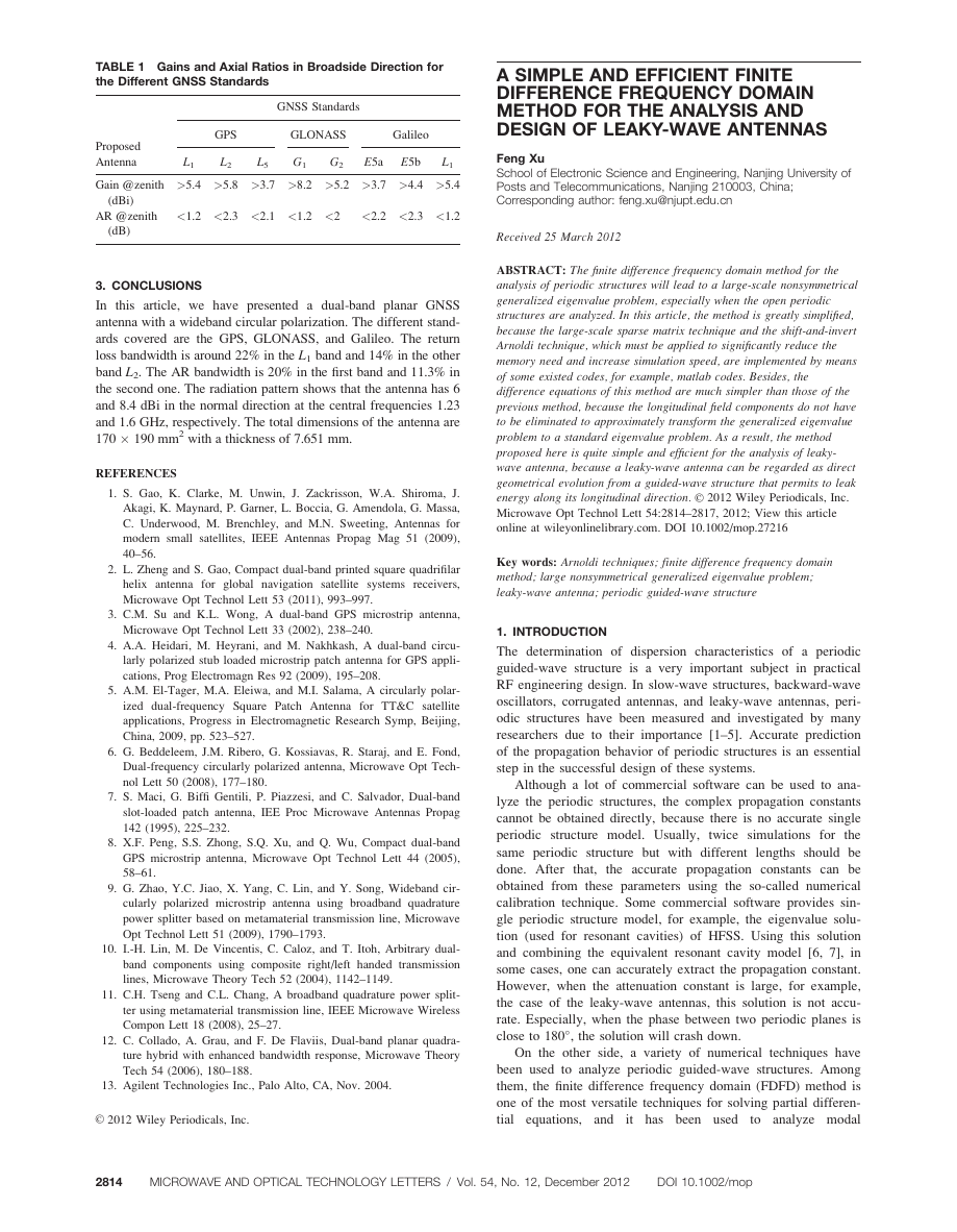
As shown in Figure 1, the periodic boundary conditions are
disposed along z direction. For the open periodic problems, the
absorbing boundary conditions can be easily set up. If the
number of meshes in z direction is p and the space step in z
direction is Dz, from Eq. (2), the periodic boundaries can be
written as,
e0ðx; y; 0Þ ¼ epðx; y; dÞ
hpþ1ðx; y; d þ Dz=2Þ ¼ h1ðx; y; Dz=2Þ
�
The difference equation of (3a) can be regarded as,
(5a)
(5b)
�
c
2
ey
�
l; m; n � 1
2
�
�
�
�
�
�
þ ey
l; m; n þ 1
2
�
�
l; m; n þ 1
2
l; m þ 1
2
ey
ez
þ 1
Dz
� 1
Dy
�
¼ �ðjxl þ rm
�
� ey
�
�
x ðl; m; nÞÞhxðl; m; nÞ
�
l; m; n � 1
2
l; m � 1
2
�
�
� ez
ð6Þ
; n
; n
Other difference equations are similar with Eq. (6). After
that, an eigenvalue problem can be obtained,
cBx ¼ Ax
(7)
where x ¼ [hx, hy, hz, ex, ey, ez]T, if the electromagnetic waves
propagate along z direction.
2.1. Structures of Matrices
From Eqs. (3) and (7), the matrix A is,
2
6666664
A ¼
H
D
H
D
H
H
H A42 A43
D
A51 H A53 H
A61 A62 H
H
H
H A15 A16
H A24 H A26
D A34 A35 H
H
H
D
H
D
H
3
7777775
(8)
where, D is a diagonal matrix, H is zero matrix, and each block
matrix Amn is bidiagonal matrix. Obviously, the matrix A is
large sparse matrix. The vector x ¼ [hx, hy, hz, ex, ey, ez]T is
always disposed by first starting along the periodic direction (z
direction). The matrix B is also a large sparse matrix,
H H H H Bh H
H H H Bh H H
H H H H H H
H Be H H H H
Be H H H H H
H H H H H H
(9)
where, Be or Bh is also a bidiagonal matrix. If the number of
the meshes in z direction equals to p. The core matrix of Be and
Bh are,
.
.
0:5
0:5
0
.
..
0
0
. .
. .
.
. .
���
0:5 0:5
. .
. .
. .
0
0
.
..
0
0:5
.
.
.
.
���
.
. .
. .
. .
0
.
.
.
0
. .
. .
.
. .
���
.
.
.
0:5
0
. .
0
.
. .
..
. .
0
0:5 0:5
���
.
. .
. .
. .
0
0:5
0:5
0
.
..
0
.
.
(10a)
(10b)
p�p
p�p
2
6666664
B ¼
2
6666664
6666664
2
core ¼
Bh
core ¼
Be
3
7777775
3
7777775
7777775
3
DOI 10.1002/mop
MICROWAVE AND OPTICAL TECHNOLOGY LETTERS / Vol. 54, No. 12, December 2012
2815
�
Figure 1 Yee meshes of single period
As a result, it can be concluded that the matrix B is a large
nonsymmetrical sparse singular matrix. By means of the Arnoldi
technique, the eigenvalues (complex propagation constants) of
this generalized eigenvalue problem can be extracted accurately
and quickly.
2.2. Sparse Matrix and Arnoldi Techniques
From above, matrix A and B are large-scale sparse matrix. The
sparse matrix techniques should be used to significantly reduce
the memory need. To simplify this process, some existed subco-
des can be applied, for example, the subcode ‘‘sparse’’ of mat-
lab software. In this case, one just needs to calculation the non-
zero values in matrix A and B and record them in a vector. At
the same time, one also needs to record their position informa-
tion in the matrices (row number and column number) and save
them into the two integer vectors. After that, using the ‘‘sparse’’
in the environment of matlab, the matrix A and B without zero
elements can be formed.
The Arnoldi method is an efficient procedure for approximat-
ing a subset of the eigensystem of the large sparse matrices
[10]. The Arnoldi method is a generalization of the Lanczos
process and reduces to that method when the matrices are sym-
metric. To greatly increase the simulation speed, the shift-and-
invert Arnoldi technique must be implemented to directly solve
the large nonsymmetrical generalized eigenvalue problem [11–
16]. Similarly, one can also use some existed codes, for exam-
ple, the code ‘‘sptarn’’ (related to the shift-and-invert Arnoldi
technique) of matlab software to bypass this complicated mathe-
matic process. At last, a simple and efficient numerical algo-
rithm for the analysis of the leaky-wave antennas can be con-
structed in the environment of matlab.
Figure 3 Comparison of the angles of maximum radiation of the
leaky-wave antenna. [Color figure can be viewed in the online issue,
which is available at wileyonlinelibrary.com]
3. NUMERICAL RESULTS
To validate the proposed method, a dielectric-inset waveguide
leaky-wave is analyzed. In Figure 2, a periodic leaky-wave
antenna based on a metal-strip-loaded dielectric inset waveguide
is illustrated. This type of open periodic waveguide supports the
propagation of leaky-wave modes, which can be used to set up
leaky-wave antenna. Due to its desirable properties, the leaky-
wave antenna is suitable to be used in millimeter waveband.
This leaky-wave antenna has been analyzed using the transverse
equivalent network method [17] and full-wave spectral-domain
method [18]. Obviously, the FDFD method can also be used to
analyze this antenna based on the versatility of the FDFD
method.
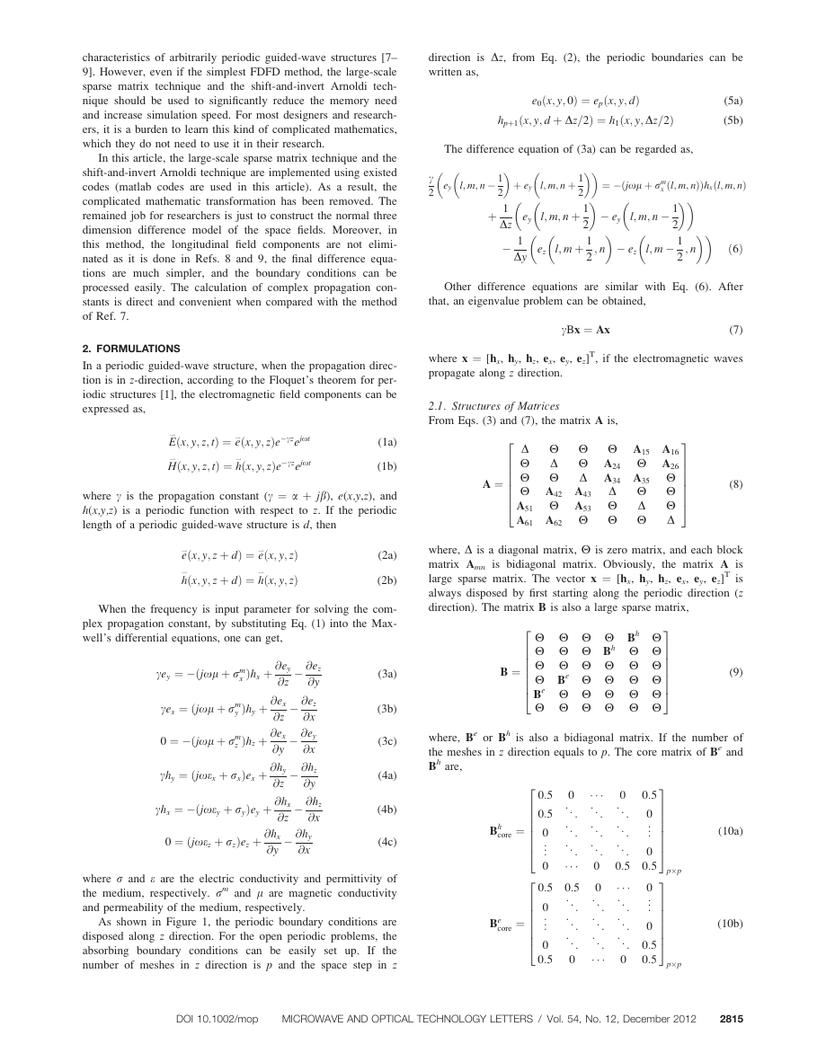
As shown in Figure 2, the wide wall of rectangular wave-
guide is a, and the narrow wall is b. The relative dielectric con-
stant
in the waveguide is 9.0. One of the narrow walls is
replaced by periodic metal strips. The width of metal strip is w,
and periodic length is p. The results of the lowest mode in Ref.
17 are used to compare with the results of the FDFD method.
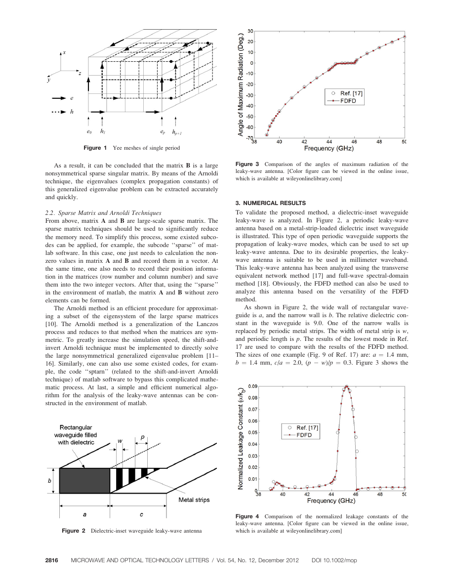
The sizes of one example (Fig. 9 of Ref. 17) are: a ¼ 1.4 mm,
b ¼ 1.4 mm, c/a ¼ 2.0, (p � w)/p ¼ 0.3. Figure 3 shows the
Figure 2 Dielectric-inset waveguide leaky-wave antenna
Figure 4 Comparison of
the normalized leakage constants of the
leaky-wave antenna. [Color figure can be viewed in the online issue,
which is available at wileyonlinelibrary.com]
2816
MICROWAVE AND OPTICAL TECHNOLOGY LETTERS / Vol. 54, No. 12, December 2012
DOI 10.1002/mop
�
angle of maximum radiation when frequency changes, which
can be calculated according to the equation,
13. M.N. Kooper, H.A. ven der Vorst, S. Poedts, and J.P. Goedbloed,
Application of the implicitly updated arnoldi method with a com-
plex shift-and-invert strategy in MHD, J Comput Phys 118 (1995),
320–329.
(11)
14. R.B. Morgan, On restarting the Arnoldi method for large nonsym-
sin hm � b
k0
where hm is the angle of maximum radiation, measured from the
broadside direction. The backward radiation phenomena can be
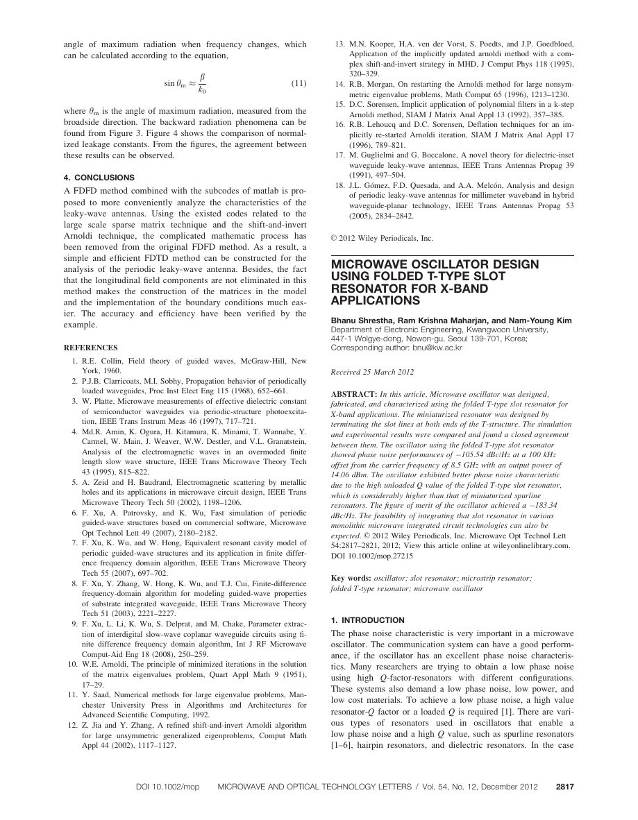
found from Figure 3. Figure 4 shows the comparison of normal-
ized leakage constants. From the figures, the agreement between
these results can be observed.
4. CONCLUSIONS
technique,
A FDFD method combined with the subcodes of matlab is pro-
posed to more conveniently analyze the characteristics of the
leaky-wave antennas. Using the existed codes related to the
large scale sparse matrix technique and the shift-and-invert
Arnoldi
the complicated mathematic process has
been removed from the original FDFD method. As a result, a
simple and efficient FDTD method can be constructed for the
analysis of the periodic leaky-wave antenna. Besides, the fact
that the longitudinal field components are not eliminated in this
method makes the construction of the matrices in the model
and the implementation of the boundary conditions much eas-
ier. The accuracy and efficiency have been verified by the
example.
REFERENCES
metric eigenvalue problems, Math Comput 65 (1996), 1213–1230.
15. D.C. Sorensen, Implicit application of polynomial filters in a k-step
Arnoldi method, SIAM J Matrix Anal Appl 13 (1992), 357–385.
16. R.B. Lehoucq and D.C. Sorensen, Deflation techniques for an im-
plicitly re-started Arnoldi iteration, SIAM J Matrix Anal Appl 17
(1996), 789–821.
17. M. Guglielmi and G. Boccalone, A novel theory for dielectric-inset
waveguide leaky-wave antennas, IEEE Trans Antennas Propag 39
(1991), 497–504.
18. J.L. G�omez, F.D. Quesada, and A.A. Melc�on, Analysis and design
of periodic leaky-wave antennas for millimeter waveband in hybrid
waveguide-planar technology, IEEE Trans Antennas Propag 53
(2005), 2834–2842.
VC 2012 Wiley Periodicals, Inc.
MICROWAVE OSCILLATOR DESIGN
USING FOLDED T-TYPE SLOT
RESONATOR FOR X-BAND
APPLICATIONS
Bhanu Shrestha, Ram Krishna Maharjan, and Nam-Young Kim
Department of Electronic Engineering, Kwangwoon University,
447-1 Wolgye-dong, Nowon-gu, Seoul 139-701, Korea;
Corresponding author: bnu@kw.ac.kr
1. R.E. Collin, Field theory of guided waves, McGraw-Hill, New
York, 1960.
Received 25 March 2012
2. P.J.B. Clarricoats, M.I. Sobhy, Propagation behavior of periodically
loaded waveguides, Proc Inst Elect Eng 115 (1968), 652–661.
3. W. Platte, Microwave measurements of effective dielectric constant
of semiconductor waveguides via periodic-structure photoexcita-
tion, IEEE Trans Instrum Meas 46 (1997), 717–721.
4. Md.R. Amin, K. Ogura, H. Kitamura, K. Minami, T. Wannabe, Y.
Carmel, W. Main, J. Weaver, W.W. Destler, and V.L. Granatstein,
Analysis of the electromagnetic waves in an overmoded finite
length slow wave structure, IEEE Trans Microwave Theory Tech
43 (1995), 815–822.
5. A. Zeid and H. Baudrand, Electromagnetic scattering by metallic
holes and its applications in microwave circuit design, IEEE Trans
Microwave Theory Tech 50 (2002), 1198–1206.
6. F. Xu, A. Patrovsky, and K. Wu, Fast simulation of periodic
guided-wave structures based on commercial software, Microwave
Opt Technol Lett 49 (2007), 2180–2182.
7. F. Xu, K. Wu, and W. Hong, Equivalent resonant cavity model of
periodic guided-wave structures and its application in finite differ-
ence frequency domain algorithm, IEEE Trans Microwave Theory
Tech 55 (2007), 697–702.
8. F. Xu, Y. Zhang, W. Hong, K. Wu, and T.J. Cui, Finite-difference
frequency-domain algorithm for modeling guided-wave properties
of substrate integrated waveguide, IEEE Trans Microwave Theory
Tech 51 (2003), 2221–2227.
9. F. Xu, L. Li, K. Wu, S. Delprat, and M. Chake, Parameter extrac-
tion of interdigital slow-wave coplanar waveguide circuits using fi-
nite difference frequency domain algorithm, Int J RF Microwave
Comput-Aid Eng 18 (2008), 250–259.
10. W.E. Arnoldi, The principle of minimized iterations in the solution
of the matrix eigenvalues problem, Quart Appl Math 9 (1951),
17–29.
11. Y. Saad, Numerical methods for large eigenvalue problems, Man-
chester University Press in Algorithms and Architectures for
Advanced Scientific Computing, 1992.
12. Z. Jia and Y. Zhang, A refined shift-and-invert Arnoldi algorithm
for large unsymmetric generalized eigenproblems, Comput Math
Appl 44 (2002), 1117–1127.
ABSTRACT: In this article, Microwave oscillator was designed,
fabricated, and characterized using the folded T-type slot resonator for
X-band applications. The miniaturized resonator was designed by
terminating the slot lines at both ends of the T-structure. The simulation
and experimental results were compared and found a closed agreement
between them. The oscillator using the folded T-type slot resonator
showed phase noise performances of �105.54 dBc/Hz at a 100 kHz
offset from the carrier frequency of 8.5 GHz with an output power of
14.06 dBm. The oscillator exhibited better phase noise characteristic
due to the high unloaded Q value of the folded T-type slot resonator,
which is considerably higher than that of miniaturized spurline
resonators. The figure of merit of the oscillator achieved a �183.34
dBc/Hz. The feasibility of integrating that slot resonator in various
monolithic microwave integrated circuit technologies can also be
expected. VC 2012 Wiley Periodicals, Inc. Microwave Opt Technol Lett
54:2817–2821, 2012; View this article online at wileyonlinelibrary.com.
DOI 10.1002/mop.27215
Key words: oscillator; slot resonator; microstrip resonator;
folded T-type resonator; microwave oscillator
1. INTRODUCTION
The phase noise characteristic is very important in a microwave
oscillator. The communication system can have a good perform-
ance, if the oscillator has an excellent phase noise characteris-
tics. Many researchers are trying to obtain a low phase noise
using high Q-factor-resonators with different configurations.
These systems also demand a low phase noise, low power, and
low cost materials. To achieve a low phase noise, a high value
resonator-Q factor or a loaded Q is required [1]. There are vari-
ous types of
resonators used in oscillators that enable a
low phase noise and a high Q value, such as spurline resonators
[1–6], hairpin resonators, and dielectric resonators. In the case
DOI 10.1002/mop
MICROWAVE AND OPTICAL TECHNOLOGY LETTERS / Vol. 54, No. 12, December 2012
2817
�


 2023年江西萍乡中考道德与法治真题及答案.doc
 2012年重庆南川中考生物真题及答案.doc
 2013年江西师范大学地理学综合及文艺理论基础考研真题.doc
 2020年四川甘孜小升初语文真题及答案I卷.doc
 2020年注册岩土工程师专业基础考试真题及答案.doc
 2023-2024学年福建省厦门市九年级上学期数学月考试题及答案.doc
 2021-2022学年辽宁省沈阳市大东区九年级上学期语文期末试题及答案.doc
 2022-2023学年北京东城区初三第一学期物理期末试卷及答案.doc
 2018上半年江西教师资格初中地理学科知识与教学能力真题及答案.doc
 2012年河北国家公务员申论考试真题及答案-省级.doc
 2020-2021学年江苏省扬州市江都区邵樊片九年级上学期数学第一次质量检测试题及答案.doc
 2022下半年黑龙江教师资格证中学综合素质真题及答案.doc