Chapter 1
Prologue
1.1
1.2
1.3
1.4
1.5
1.6
1.7
Introduction . . . . . . . . . . . . . . . . . . . . . . . . . . . . . . . . . . . . . . . . . . . . . . . . . . .
Historical Background of Light
. . . . . . . . . . . . . . . . . . . . . . . . . . . . . . . . . . .
1.2.1 Electromagnetic spectrum . . . . . . . . . . . . . . . . . . . . . . . . . . . . . . . . . .
Optical Wave Models
. . . . . . . . . . . . . . . . . . . . . . . . . . . . . . . . . . . . . . . . . . .
1.3.1 Diffraction . . . . . . . . . . . . . . . . . . . . . . . . . . . . . . . . . . . . . . . . . . . . . .
Atmospheric Effects
. . . . . . . . . . . . . . . . . . . . . . . . . . . . . . . . . . . . . . . . . . . .
1.4.1 Atmospheric structure with altitude . . . . . . . . . . . . . . . . . . . . . . . . . .
1.4.2 Absorption and scattering . . . . . . . . . . . . . . . . . . . . . . . . . . . . . . . . . .
1.4.3 Meteorological phenomena . . . . . . . . . . . . . . . . . . . . . . . . . . . . . . . . .
1.4.4 Optical turbulence . . . . . . . . . . . . . . . . . . . . . . . . . . . . . . . . . . . . . . . .
Application Areas
. . . . . . . . . . . . . . . . . . . . . . . . . . . . . . . . . . . . . . . . . . . . . .
1.5.1 Free space optics . . . . . . . . . . . . . . . . . . . . . . . . . . . . . . . . . . . . . . . . .
1.5.2 Laser satellite communication systems . . . . . . . . . . . . . . . . . . . . . . . .
1.5.3 Laser radar systems . . . . . . . . . . . . . . . . . . . . . . . . . . . . . . . . . . . . . . .
1.5.4 Other application areas
. . . . . . . . . . . . . . . . . . . . . . . . . . . . . . . . . . . .
A Brief Review of Communication Systems . . . . . . . . . . . . . . . . . . . . . . . . .
1.6.1 Direct detection systems . . . . . . . . . . . . . . . . . . . . . . . . . . . . . . . . . . .
1.6.2 Coherent detection system . . . . . . . . . . . . . . . . . . . . . . . . . . . . . . . . .
1.6.3 Channel models . . . . . . . . . . . . . . . . . . . . . . . . . . . . . . . . . . . . . . . . . .
Summary and Overview of the Book . . . . . . . . . . . . . . . . . . . . . . . . . . . . . . .
References
. . . . . . . . . . . . . . . . . . . . . . . . . . . . . . . . . . . . . . . . . . . . . . . . . . . .
4
5
6
8
8
9
10
11
13
14
15
15
17
20
21
22
23
24
25
26
32
Overview: In this first chapter we present an introduction/overview of
material that is related to the propagation of laser beams through random
media like the atmosphere. The intent here is to provide the reader with a
broad view of
the distraction of mathematical
detail that is required in other chapters of the text. The wavelengths of
interest throughout the text are the visible and infrared (IR) portions of the
electromagnetic spectrum, although some results can readily be applied to
other wavelengths like millimeter waves and, under some conditions,
microwaves.
the subject without
3
�
4
Chapter 1
We begin by briefly introducing some of the standard optical wave models
like the plane wave, spherical wave, and lowest-order Gaussian-beam wave.
Next, we describe the origin of certain atmospheric effects (including
meteorological phenomena) associated with propagating optical waves.
Some of the traditional application areas are discussed for laser beam propa-
gation—free space optical communications (FSO), laser radar, imaging, and
remote sensing—followed by a short historical summary of developmental
programs for laser satellite communication systems (lasersatcom) in the
United States, Europe, and Japan. In the last section of this chapter we
present an overview of the material contained in the remaining chapters,
delineating the primary topics to be treated in each individual chapter.
1.1 Introduction
it was suggested that
The first working LASER, an acronym standing for Light Amplification by Stimu-
lated Emission of Radiation, was introduced in 1960 and from that point in time
the scientific community concentrated a great deal of attention on its possible
applications. In particular,
lasers be used to extend
radio-frequency (RF) atmospheric communication and radar techniques to the
optical-frequency band. Other areas of interest for laser applications include weap-
onry, ranging, remote sensing, target designation, adaptive optics, and medical
uses, among others. However, all systems that utilize optical (visible) or infrared
(IR) waves must take into account general propagation effects associated with the
medium in which it propagates in addition to effects associated with the wave
itself. The propagation medium in many cases is the turbulent atmosphere for
which small index-of-refraction fluctuations along the propagation path cause a
variety of deleterious effects on the wave.
Random fluctuations in the refractive index of the atmosphere are directly
associated with microscopic temperature fluctuations caused by turbulent motion
of the air due to winds and convection. Although these refractive-index fluctu-
ations are only a few parts in 106, a propagating optical wave passes through a
large number of refractive-index inhomogeneities, so their cumulative effect on
the optical wave is quite profound. For example, refractive-index fluctuations
cause the twinkling of stars and limit the “seeing” ability of astronomers to
resolve small objects to within a few seconds of arc. This latter atmospheric
effect motivates the use of adaptive optics techniques and the placement of
large telescopes in space, such as the famous Hubble telescope.
Early investigations concerning the propagation of electromagnetic radiation
and other waves through random media involved the propagation of starlight
through the atmosphere, propagation of sound waves through the atmosphere
and ocean, propagation of microwaves through planetary atmospheres, and
propagation of radio waves through the ionosphere and interplanetary space.
Thus, some of the theoretical work concerning the propagation of an optical
�
Prologue
5
wave in a turbulent medium was done prior to the introduction of the laser.
The propagation of laser light, which is simply one form of electromagnetic
radiation,
is a subtopic of much of this early research. Both Chernov and
Tatarskii published monographs before 1960 on the propagation of optical
plane waves and spherical waves through turbulence; these monographs were
subsequently translated into English in 1960 and 1961, respectively [1,2].
Additional background on optical wave propagation in random media, along
with many early references, can also be found in Lawrence and Strohbehn
[3], Prokhorov et al. [4], Fante [5,6], Uscinski [7], Strohbehn [8], Ishimaru
[9], Zuev [10], Rytov et al. [11], Tatarskii et al. [12], Sasiela [13], Andrews
et al. [14], and Wheelon [15,16].
1.2 Historical Background of Light
Until about the middle of the seventeenth century, the general belief of the scien-
tific community [including Newton (1642 – 1727)] was that light consisted of a
stream of corpuscles. These “corpuscles” emitted by light sources traveled in
straight lines, could penetrate transparent materials, and were reflected from
the surfaces of opaque objects. Laws of refraction were established by Snell
(1591 – 1626), diffraction was discovered by Grimaldi (1618 – 1663), and double
refraction was discovered by Bartholinus (1625 – 1698). However, discoveries
like diffraction were particularly puzzling to explain on the basis of the corpuscular
theory. For example, it was difficult under the corpuscular theory to explain why
shadows reach a limiting sharpness as the size of the source becomes small, and
why fringes appear on the light side of the shadow of a sharp edge.
Huygens (1629 – 1695) showed in 1670 that the laws of reflection and refraction
could be explained on the basis of a wave theory, although he thought light
waves were longitudinal (in the direction of propagation) rather than transversal
(perpendicular to the direction of propagation). It is interesting that even though
the idea that light might involve a wave motion of some kind arose in the
middle of the seventeenth century, a wave theory of light was not widely accepted
by the scientific community until the end of the eighteenth century, mostly because
of Newton’s support of the corpuscular theory and his long-lasting influence.
In the early 1800s, the interference experiments of Young (1773 – 1829), Fresnel
(1788 – 1827), and others finally put the corpuscular theory to rest. Young’s exper-
iments enabled him to measure the wavelength of light waves and Fresnel showed
that the rectilinear propagation of light as well as the diffraction effects observed
by Grimaldi and others could be accounted for by the behavior of waves of
short wavelength.
The speed of light was directly measured in 1850 and found to be c ¼ 3 � 108
m/s, confirming the estimates made many years earlier first by Romer (1644 –
1710) and latter by Bradley (1693 – 1762). Knowledge of the speed of light was
important for Maxwell’s (1831 – 1879) theory of electromagnetic waves published
in 1873. Hertz (1857 – 1894) discovered the photoelectric effect in 1887 and
became the first to verify Maxwell’s theory by producing short wavelength
�
6
Chapter 1
radiation (microwaves) that possessed all the properties of waves. However, it
took the quantum theory of Planck (1858 – 1947), as interpreted by Einstein
(1879 – 1955) in 1905, to explain the photoelectric effect and to introduce the
notion that wave energy of light is concentrated in small packets called photons.
1.2.1 Electromagnetic spectrum
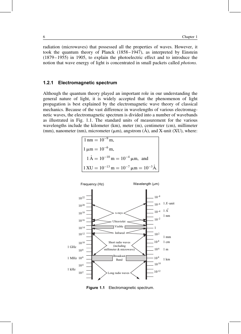
Although the quantum theory played an important role in our understanding the
general nature of light, it is widely accepted that the phenomenon of light
propagation is best explained by the electromagnetic wave theory of classical
mechanics. Because of the vast difference in wavelengths of various electromag-
netic waves, the electromagnetic spectrum is divided into a number of wavebands
as illustrated in Fig. 1.1. The standard units of measurement for the various
wavelengths include the kilometer (km), meter (m), centimeter (cm), millimeter
(mm), nanometer (nm), micrometer (mm), angstrom (A˚ ), and X-unit (XU), where:
1 nm ¼ 10
1 mm ¼ 10
1 �A ¼ 10
1 XU ¼ 10
�9 m,
�6 m,
�10 m ¼ 10
�13 m ¼ 10
�4 mm, and
�7 mm ¼ 10
�3 �A:
Frequency (Hz)
Wavelength (µm)
10 22
10 20
10 18
10 16
10 14
10 12
10 10
10 8
1 GHz
1 MHz
10 6
1 kHz
10 4
10 2
x-rays
Ultraviolet
Visible
Infrared
Short radio waves
(including
millimeter & microwave)
Broadcast
Band
Long radio waves
10 -8
10 -6
10 -4
10 -2
1
10 2
1 X- unit
o
1 A
1 nm
1 mm
10 4
1 cm
10 6
1 m
1 km
10 8
10 10
10 12
Figure 1.1 Electromagnetic spectrum.
�
Prologue
7
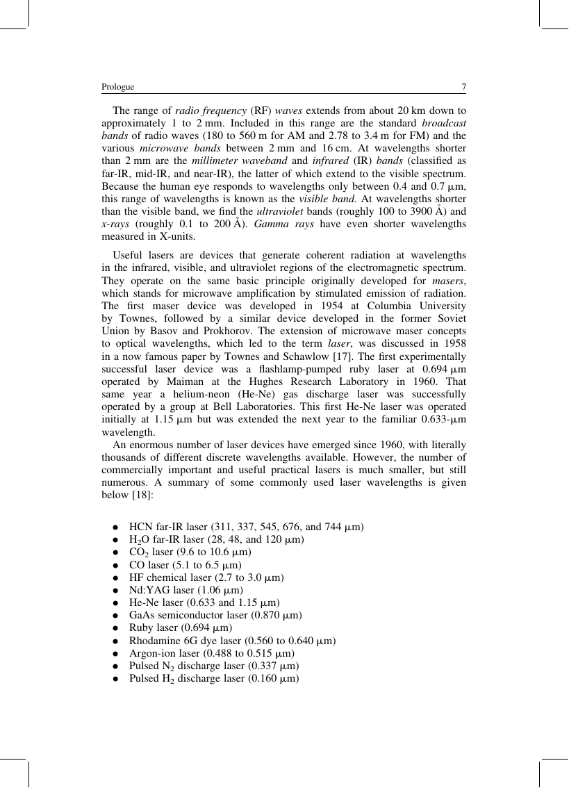
The range of radio frequency (RF) waves extends from about 20 km down to
approximately 1 to 2 mm. Included in this range are the standard broadcast
bands of radio waves (180 to 560 m for AM and 2.78 to 3.4 m for FM) and the
various microwave bands between 2 mm and 16 cm. At wavelengths shorter
than 2 mm are the millimeter waveband and infrared (IR) bands (classified as
far-IR, mid-IR, and near-IR), the latter of which extend to the visible spectrum.
Because the human eye responds to wavelengths only between 0.4 and 0.7 mm,
this range of wavelengths is known as the visible band. At wavelengths shorter
than the visible band, we find the ultraviolet bands (roughly 100 to 3900 A˚ ) and
x-rays (roughly 0.1 to 200 A˚ ). Gamma rays have even shorter wavelengths
measured in X-units.
Useful lasers are devices that generate coherent radiation at wavelengths
in the infrared, visible, and ultraviolet regions of the electromagnetic spectrum.
They operate on the same basic principle originally developed for masers,
which stands for microwave amplification by stimulated emission of radiation.
The first maser device was developed in 1954 at Columbia University
by Townes, followed by a similar device developed in the former Soviet
Union by Basov and Prokhorov. The extension of microwave maser concepts
to optical wavelengths, which led to the term laser, was discussed in 1958
in a now famous paper by Townes and Schawlow [17]. The first experimentally
laser device was a flashlamp-pumped ruby laser at 0.694 mm
successful
operated by Maiman at
the Hughes Research Laboratory in 1960. That
same year a helium-neon (He-Ne) gas discharge laser was successfully
operated by a group at Bell Laboratories. This first He-Ne laser was operated
initially at 1.15 mm but was extended the next year to the familiar 0.633-mm
wavelength.
An enormous number of laser devices have emerged since 1960, with literally
thousands of different discrete wavelengths available. However, the number of
commercially important and useful practical lasers is much smaller, but still
numerous. A summary of some commonly used laser wavelengths is given
below [18]:
. HCN far-IR laser (311, 337, 545, 676, and 744 mm)
. H2O far-IR laser (28, 48, and 120 mm)
. CO2 laser (9.6 to 10.6 mm)
. CO laser (5.1 to 6.5 mm)
. HF chemical laser (2.7 to 3.0 mm)
. Nd:YAG laser (1.06 mm)
. He-Ne laser (0.633 and 1.15 mm)
. GaAs semiconductor laser (0.870 mm)
. Ruby laser (0.694 mm)
. Rhodamine 6G dye laser (0.560 to 0.640 mm)
. Argon-ion laser (0.488 to 0.515 mm)
. Pulsed N2 discharge laser (0.337 mm)
. Pulsed H2 discharge laser (0.160 mm)
�
8
Chapter 1
1.3 Optical Wave Models
There are several basic geometries used to describe various optical/IR wave
models. Among these are the following, where propagation is assumed to be
along the z-axis:
. Plane wave—an unbounded wave with constant amplitude A0 and constant
phase w0, described in the plane of the transmitter (z ¼ 0) by
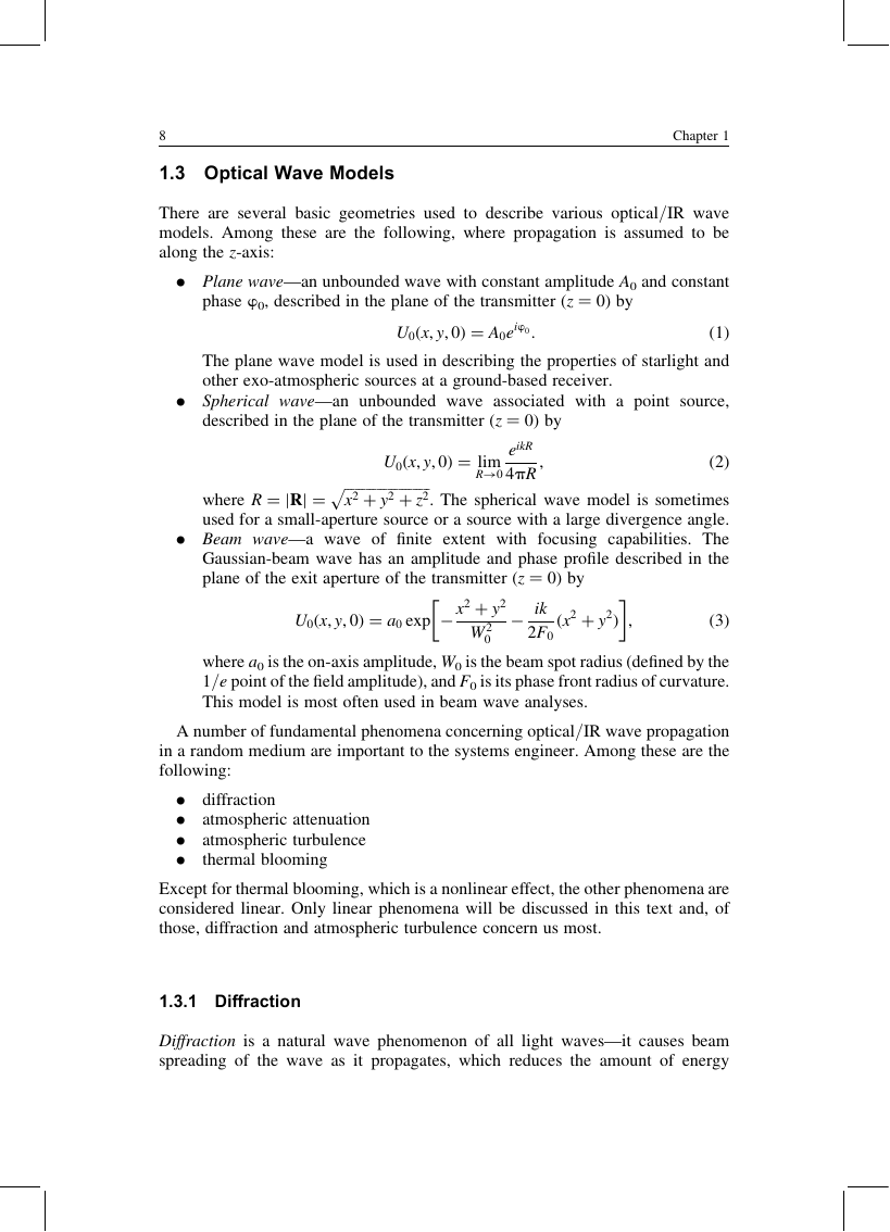
U0(x, y, 0) ¼ A0eiw0:
(1)
The plane wave model is used in describing the properties of starlight and
other exo-atmospheric sources at a ground-based receiver.
Spherical wave—an unbounded wave associated with a point source,
described in the plane of the transmitter (z ¼ 0) by
.
U0(x, y, 0) ¼ lim
R!0
p
ffiffiffiffiffiffiffiffiffiffiffiffiffiffiffiffiffiffiffiffiffiffiffiffi
x2 þ y2 þ z2
eikR
4pR
where R ¼ jRj ¼
. The spherical wave model is sometimes
used for a small-aperture source or a source with a large divergence angle.
. Beam wave—a wave of finite extent with focusing capabilities. The
Gaussian-beam wave has an amplitude and phase profile described in the
plane of the exit aperture of the transmitter (z ¼ 0) by
�
�
,
(2)
U0(x, y, 0) ¼ a0 exp � x2 þ y2
� ik
2F0
(x2 þ y2)
,
(3)
W 2
0
where a0 is the on-axis amplitude, W0 is the beam spot radius (defined by the
1/e point of the field amplitude), and F0 is its phase front radius of curvature.
This model is most often used in beam wave analyses.
A number of fundamental phenomena concerning optical/IR wave propagation
in a random medium are important to the systems engineer. Among these are the
following:
.
.
.
.
diffraction
atmospheric attenuation
atmospheric turbulence
thermal blooming
Except for thermal blooming, which is a nonlinear effect, the other phenomena are
considered linear. Only linear phenomena will be discussed in this text and, of
those, diffraction and atmospheric turbulence concern us most.
1.3.1 Diffraction
Diffraction is a natural wave phenomenon of all light waves—it causes beam
spreading of the wave as it propagates, which reduces the amount of energy
�
Prologue
9
within any given spot size inside the beam diameter. In addition, the phase front
radius of curvature of the propagating optical wave is also constantly increasing.
A laser beam is subject to further spreading when atmospheric turbulence is
present.
The amount of beam spreading due to pure diffraction depends on the wave-
length l of the optical wave, shape of the phase front (i.e., spherical, uniform,
etc.), and size of the emitting aperture. In our treatment we consider primarily
the Gaussian-beam wave, or its limiting case of a uniform amplitude plane
wave or spherical wave. The notion of “beam spot size” has an unambiguous phys-
ical meaning only for the simple Gaussian beam for which the irradiance (inten-
sity) has a Gaussian profile and produces a single spot in the observation plane.
The beam spot size along the propagation path has its minimum value at the
beam waist, and the amount of beam spreading at large distances from the waist
can be estimated by the beam divergence angle (see Fig. 1.2)
uB ffi l
pWB
,
z � pW 2
l
B
,
(4)
where WB is the beam radius at the waist. In Chap. 4 we will develop more
complete relations for diffractive beam spreading.
1.4 Atmospheric Effects
It is a common experience to notice the changing view of distant objects or a city
skyline from day to day as atmospheric conditions vary. These varying conditions
are caused by factors like rain, snow, sleet, fog, haze, pollution, etc., that can
greatly limit our ability to view distant objects. These same factors also affect
the transmission of electromagnetic radiation through the atmosphere, particularly
optical waves.
The three primary atmospheric phenomena that affect optical wave propagation
are absorption, scattering, and refractive-index fluctuations (i.e., optical turbu-
lence). Absorption and scattering by the constituent gases and particulates of the
atmosphere are wavelength dependent and give rise primarily to attenuation of
an optical wave. Index of refraction fluctuations lead to irradiance fluctuations,
Beam Waist = 2WB
θB
z
Figure 1.2 Far-field divergence angle.
�
10
Chapter 1
beam spreading, and loss of spatial coherence of the optical wave, among other
effects. Unfortunately, these detrimental effects have far-reaching consequences
on astronomical imaging, free-space optical communications, remote sensing,
laser radar, and other applications that require the transmission of optical waves
through the atmosphere.
1.4.1 Atmospheric structure with altitude
The atmosphere is a gaseous envelope that surrounds the Earth and extends to
several hundred kilometers above the surface. Over 98% of the atmosphere by
volume is comprised of the elements nitrogen and oxygen. The major constituents
of the atmosphere are water vapor, carbon dioxide, nitrous oxide, carbon monox-
ide, and ozone. Based mostly on temperature variations, the Earth’s atmosphere is
divided into four primary layers (see Fig. 1.3):
. Troposphere—extends up to 11 km and contains roughly 75% of the Earth’s
atmospheric mass. Maximum air temperature occurs near the surface of the
Earth, but decreases with altitude to 2558C. The tropopause is an isother-
mal layer extending 9 km above the troposphere where air temperature
remains constant at 2558C. The tropopause and troposphere together are
known as the lower atmosphere.
. Stratosphere—layer above the tropopause, which extends from 20 km up to
48 km altitude. The air temperature is roughly constant in the very lowest
e
d
u
t
i
t
l
A
Thermosphere
Mesopause
Mesosphere
Stratopause
Stratosphere
Tropopause
Troposphere
600 km
90 km
80 km
50 km
48 km
20 km
11 km
0 km
-100 -80
-60
-40
-20
0 20
Earth
Temperature°C
Figure 1.3 Diagram depicting various atmospheric layers and air temperature.
�


 2023年江西萍乡中考道德与法治真题及答案.doc
 2012年重庆南川中考生物真题及答案.doc
 2013年江西师范大学地理学综合及文艺理论基础考研真题.doc
 2020年四川甘孜小升初语文真题及答案I卷.doc
 2020年注册岩土工程师专业基础考试真题及答案.doc
 2023-2024学年福建省厦门市九年级上学期数学月考试题及答案.doc
 2021-2022学年辽宁省沈阳市大东区九年级上学期语文期末试题及答案.doc
 2022-2023学年北京东城区初三第一学期物理期末试卷及答案.doc
 2018上半年江西教师资格初中地理学科知识与教学能力真题及答案.doc
 2012年河北国家公务员申论考试真题及答案-省级.doc
 2020-2021学年江苏省扬州市江都区邵樊片九年级上学期数学第一次质量检测试题及答案.doc
 2022下半年黑龙江教师资格证中学综合素质真题及答案.doc