CiA Draft Standard 404
CANopen
Device Profile Measuring Devices and Closed-
Loop Controllers
Version 1.2
Date: 15. May 2002
© CAN in Automation (CiA)
�
CONTENTS
Measurement Devices and Closed Loop Controllers
CiA DS 404 V1.2
General information on licensing and patents
CAN in AUTOMATION (CiA) calls attention to the possibility that some of the elements of this CiA
specification may be subject of patent rights. CiA shall not be responsible for identifying any or all such
patent rights.
© CiA 2005-01-01
All rights reserved. Unless otherwise specified, no part of this publication may be reproduced or utilized in any form or by any
means, electronic or mechanical, including photocopying and microfilm, without permission in writing from CiA at the address
below.
CAN in Automation e. V.
Am Weichselgarten 26
DE - 91058 Erlangen, Germany
Tel.: +49-9131-69086-0
Fax: +49-9131-69086-79
Url: www.can-cia.org
Email: headquarters@can-cia.org
2
�
CONTENTS
Measurement Devices and Closed Loop Controllers
CiA DS 404 V1.2
CONTENTS
1
2
3
4
4.1
4.2
SCOPE..................................................................................................................9
REFERENCES.....................................................................................................10
DEFINITIONS AND ABBREVIATIONS..................................................................11
OPERATING PRINCIPLE.....................................................................................12
Introduction .................................................................................................12
General object dictionary layout....................................................................13
4.2.1
Digital input function block......................................................................15
4.2.2
Analogue input function block .................................................................15
4.2.3
Digital output function block....................................................................16
4.2.4
Analogue output function block ...............................................................17
4.2.5
Controller function block.........................................................................18
4.2.6
Alarm function block...............................................................................19
4.2.7
Device function block .............................................................................19
5
ERROR HANDLING.............................................................................................20
5.1
5.2
5.3
5.4
Principle......................................................................................................20
Error behaviour............................................................................................20
Error code meanings....................................................................................20
Additional error codes ..................................................................................21
6
PRE-DEFINITIONS ..............................................................................................22
6.1
6.2
6.3
Principle......................................................................................................22
Naming conventions ....................................................................................22
PDO Mapping..............................................................................................22
6.3.1
Object 1000h: Device type......................................................................22
6.3.2
Object 1001h: Error Register ..................................................................22
6.3.3
Object 1029h: Error Behaviour................................................................23
6.3.4
1st receive PDO parameters (Received Process Values) .........................24
6.3.5
1st transmit PDO parameters (Analogue Input)........................................25
6.3.6
2nd receive PDO parameters (Command Values for Controller)................25
6.3.7
2nd transmit PDO parameters (Effective Controller Output) ......................26
3
�
CONTENTS
Measurement Devices and Closed Loop Controllers
CiA DS 404 V1.2
6.3.8
3rd receive PDO parameters (alternate received process value) ..............26
6.3.9
3rd transmit PDO parameters (alarm)......................................................27
6.3.10
4th receive PDO parameters (Digital Output) ...........................................27
6.3.11
4th transmit PDO parameters (Digital Input).............................................28
6.3.12
5th receive PDO parameters (Control Bytes) ...........................................28
6.3.13
6th receive PDO parameters (Multiplexor PDO) .......................................29
7
OBJECT DICTIONARY ........................................................................................30
7.1
Survey object dictionary ...............................................................................31
7.1.1
Digital input function block......................................................................31
7.1.2
Analogue input function block .................................................................31
7.1.3
Digital output function block....................................................................33
7.1.4
Analogue output function block ...............................................................33
7.1.5
Controller function block.........................................................................34
7.1.6
Alarm function block...............................................................................36
7.1.7
Device function block .............................................................................37
7.2
Detailed object specification .........................................................................38
7.2.1
Object 6000h: DI Read state 8 Input Lines...............................................38
7.2.2
Object 6002h: DI Polarity 8 Input Lines....................................................39
7.2.3
Object 6020h: DI Read state 1 Input Lines...............................................40
7.2.4
Object 6030h: DI Polarity 1 Input Lines....................................................41
7.2.5
Object x100h: AI Input FV ......................................................................42
7.2.6
Object x103h: AI Interrupt delta input FV .................................................43
7.2.7
Object 6110h: AI Sensor type .................................................................44
7.2.8
Object 6111h: AI Autocalibration.............................................................45
7.2.9
Object 6112h: AI Operating mode ...........................................................47
7.2.10
Object 6114h: Al ADC sample rate..........................................................48
7.2.11
Object x120h: AI Input scaling 1 FV ........................................................49
7.2.12
Object x121h: AI Input scaling 1 PV ........................................................50
7.2.13
Object x122h: AI Input scaling 2 FV ........................................................51
7.2.14
Object x123h: AI Input scaling 2 PV ........................................................52
7.2.15
Object x124h: AI Input offset...................................................................53
4
�
CONTENTS
Measurement Devices and Closed Loop Controllers
CiA DS 404 V1.2
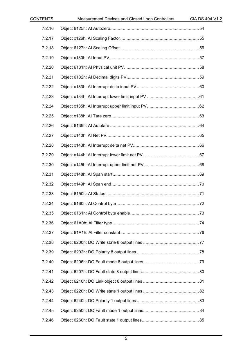
7.2.16
Object 6125h: AI Autozero......................................................................54
7.2.17
Object x126h: AI Scaling Factor..............................................................55
7.2.18
Object 6127h: AI Scaling Offset ..............................................................56
7.2.19
Object x130h: AI Input PV ......................................................................57
7.2.20
Object 6131h: AI Physical unit PV...........................................................58
7.2.21
Object 6132h: AI Decimal digits PV.........................................................59
7.2.22
Object x133h: AI Interrupt delta input PV.................................................60
7.2.23
Object x134h: AI Interrupt lower limit input PV .........................................61
7.2.24
Object x135h: AI Interrupt upper limit input PV.........................................62
7.2.25
Object x138h: AI Tare zero.....................................................................63
7.2.26
Object 6139h: AI Autotare ......................................................................64
7.2.27
Object x140h: AI Net PV.........................................................................65
7.2.28
Object x143h: AI Interrupt delta net PV....................................................66
7.2.29
Object x144h: AI Interrupt lower limit net PV ............................................67
7.2.30
Object x145h: AI Interrupt upper limit net PV ...........................................68
7.2.31
Object x148h: AI Span start....................................................................69
7.2.32
Object x149h: AI Span end.....................................................................70
7.2.33
Object 6150h: AI Status .........................................................................71
7.2.34
Object 6160h: AI Control byte.................................................................72
7.2.35
Object 6161h: AI Control byte enable ......................................................73
7.2.36
Object 61A0h: Al Filter type ....................................................................74
7.2.37
Object 61A1h: Al Filter constant..............................................................76
7.2.38
Object 6200h: DO Write state 8 output lines ............................................77
7.2.39
Object 6202h: DO Polarity 8 output lines .................................................78
7.2.40
Object 6206h: DO Fault mode 8 output lines............................................79
7.2.41
Object 6207h: DO Fault state 8 output lines.............................................80
7.2.42
Object 6210h: DO Link object 8 output lines ............................................81
7.2.43
Object 6220h: DO Write state 1 output lines ............................................82
7.2.44
Object 6240h: DO Polarity 1 output lines .................................................83
7.2.45
Object 6250h: DO Fault mode 1 output lines............................................84
7.2.46
Object 6260h: DO Fault state 1 output lines.............................................85
5
�
CONTENTS
Measurement Devices and Closed Loop Controllers
CiA DS 404 V1.2
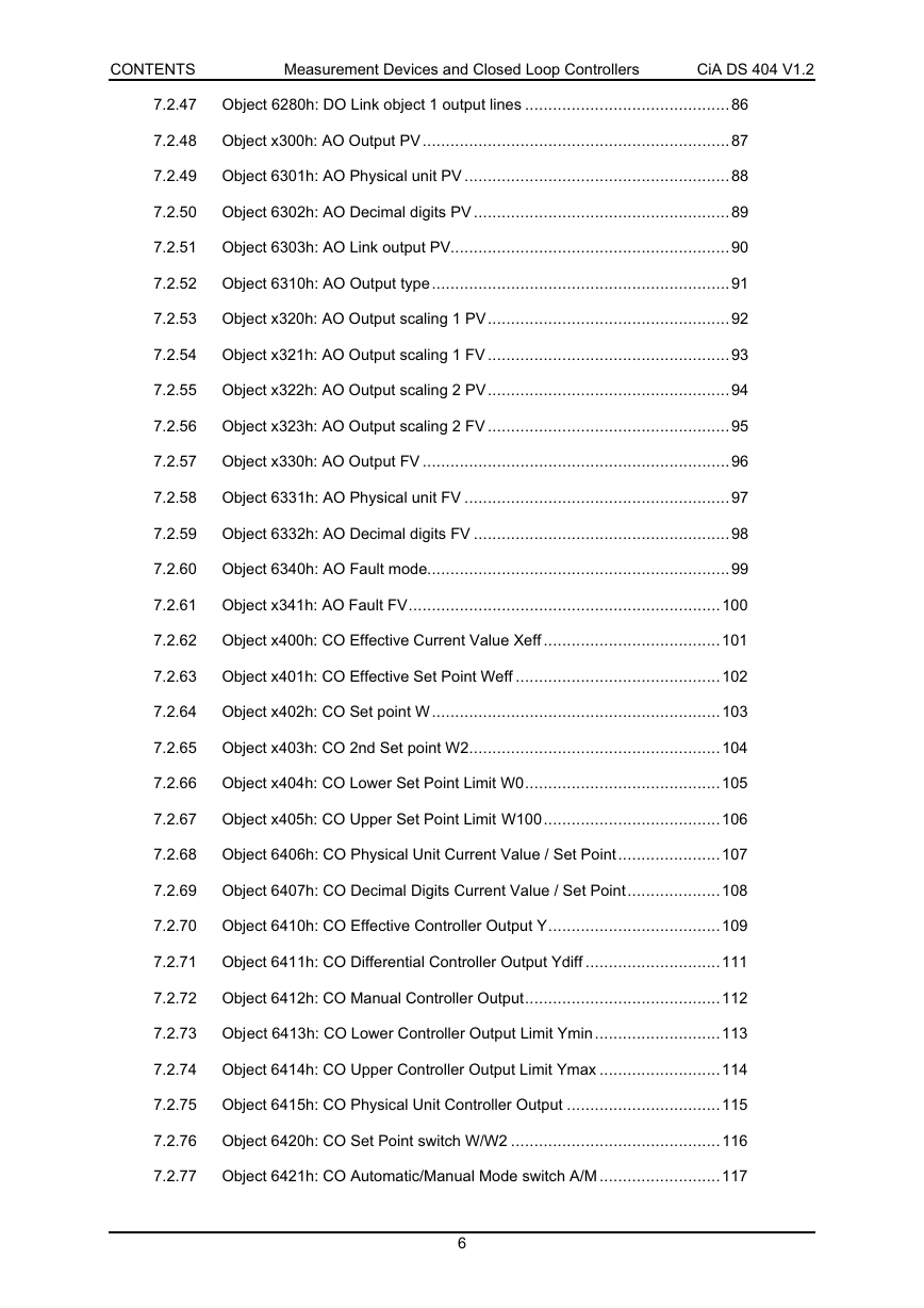
7.2.47
Object 6280h: DO Link object 1 output lines ............................................86
7.2.48
Object x300h: AO Output PV ..................................................................87
7.2.49
Object 6301h: AO Physical unit PV .........................................................88
7.2.50
Object 6302h: AO Decimal digits PV .......................................................89
7.2.51
Object 6303h: AO Link output PV............................................................90
7.2.52
Object 6310h: AO Output type ................................................................91
7.2.53
Object x320h: AO Output scaling 1 PV....................................................92
7.2.54
Object x321h: AO Output scaling 1 FV ....................................................93
7.2.55
Object x322h: AO Output scaling 2 PV....................................................94
7.2.56
Object x323h: AO Output scaling 2 FV ....................................................95
7.2.57
Object x330h: AO Output FV ..................................................................96
7.2.58
Object 6331h: AO Physical unit FV .........................................................97
7.2.59
Object 6332h: AO Decimal digits FV .......................................................98
7.2.60
Object 6340h: AO Fault mode.................................................................99
7.2.61
Object x341h: AO Fault FV...................................................................100
7.2.62
Object x400h: CO Effective Current Value Xeff ......................................101
7.2.63
Object x401h: CO Effective Set Point Weff ............................................102
7.2.64
Object x402h: CO Set point W ..............................................................103
7.2.65
Object x403h: CO 2nd Set point W2......................................................104
7.2.66
Object x404h: CO Lower Set Point Limit W0..........................................105
7.2.67
Object x405h: CO Upper Set Point Limit W100......................................106
7.2.68
Object 6406h: CO Physical Unit Current Value / Set Point......................107
7.2.69
Object 6407h: CO Decimal Digits Current Value / Set Point....................108
7.2.70
Object 6410h: CO Effective Controller Output Y.....................................109
7.2.71
Object 6411h: CO Differential Controller Output Ydiff .............................111
7.2.72
Object 6412h: CO Manual Controller Output..........................................112
7.2.73
Object 6413h: CO Lower Controller Output Limit Ymin ...........................113
7.2.74
Object 6414h: CO Upper Controller Output Limit Ymax ..........................114
7.2.75
Object 6415h: CO Physical Unit Controller Output .................................115
7.2.76
Object 6420h: CO Set Point switch W/W2 .............................................116
7.2.77
Object 6421h: CO Automatic/Manual Mode switch A/M ..........................117
6
�
CONTENTS
Measurement Devices and Closed Loop Controllers
CiA DS 404 V1.2
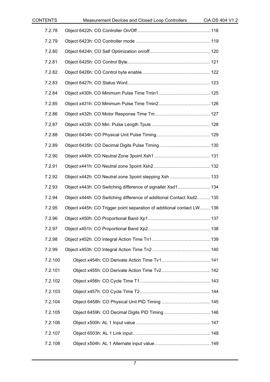
7.2.78
Object 6422h: CO Controller On/Off......................................................118
7.2.79
Object 6423h: CO Controller mode .......................................................119
7.2.80
Object 6424h: CO Self Optimization on/off.............................................120
7.2.81
Object 6425h: CO Control Byte.............................................................121
7.2.82
Object 6426h: CO Control byte enable ..................................................122
7.2.83
Object 6427h: CO Status Word.............................................................123
7.2.84
Object x430h: CO Minimum Pulse Time Tmin1......................................125
7.2.85
Object x431h: CO Minimum Pulse Time Tmin2......................................126
7.2.86
Object x432h: CO Motor Response Time Tm.........................................127
7.2.87
Object x433h: CO Min. Pulse Length Tpuls ...........................................128
7.2.88
Object 6434h: CO Physical Unit Pulse Timing........................................129
7.2.89
Object 6435h: CO Decimal Digits Pulse Timing......................................130
7.2.90
Object x440h: CO Neutral Zone 3point Xsh1 .........................................131
7.2.91
Object x441h: CO Neutral zone 3point Xsh2..........................................132
7.2.92
Object x442h: CO Neutral zone 3point stepping Xsh ..............................133
7.2.93
Object x443h: CO Switching difference of signaller Xsd1........................134
7.2.94
Object x444h: CO Switching difference of additional Contact Xsd2..........135
7.2.95
Object x445h: CO Trigger point separation of additional contact LW........136
7.2.96
Object x450h: CO Proportional Band Xp1..............................................137
7.2.97
Object x451h: CO Proportional Band Xp2..............................................138
7.2.98
Object x452h: CO Integral Action Time Tn1...........................................139
7.2.99
Object x453h: CO Integral Action Time Tn2...........................................140
7.2.100
Object x454h: CO Derivate Action Time Tv1....................................141
7.2.101
Object x455h: CO Derivate Action Time Tv2....................................142
7.2.102
Object x456h: CO Cycle Time T1....................................................143
7.2.103
Object x457h: CO Cycle Time T2....................................................144
7.2.104
Object 6458h: CO Physical Unit PID Timing ....................................145
7.2.105
Object 6459h: CO Decimal Digits PID Timing ..................................146
7.2.106
Object x500h: AL 1 Input value .......................................................147
7.2.107
Object 6503h: AL 1 Link input.........................................................148
7.2.108
Object x504h: AL 1 Alternate input value .........................................149
7
�
CONTENTS
Measurement Devices and Closed Loop Controllers
CiA DS 404 V1.2
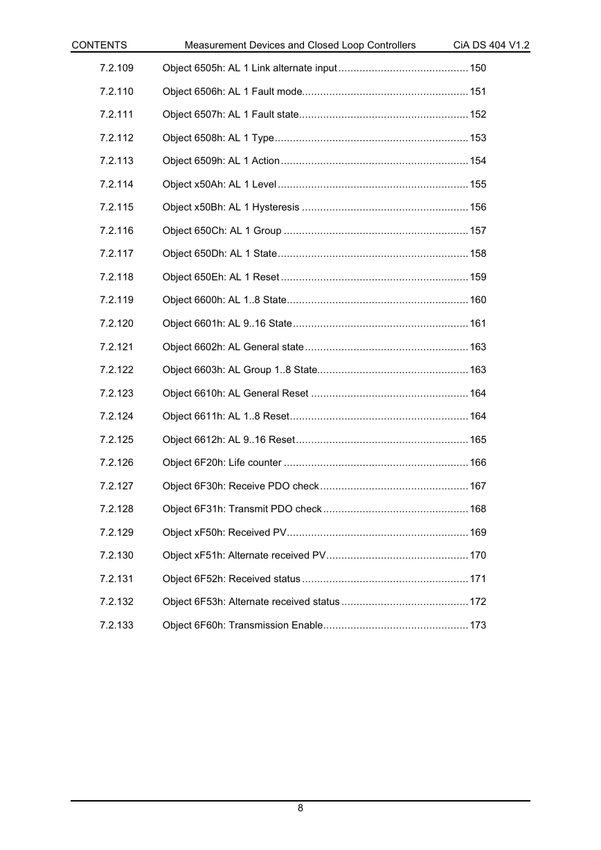
7.2.109
Object 6505h: AL 1 Link alternate input ...........................................150
7.2.110
Object 6506h: AL 1 Fault mode.......................................................151
7.2.111
Object 6507h: AL 1 Fault state........................................................152
7.2.112
Object 6508h: AL 1 Type................................................................153
7.2.113
Object 6509h: AL 1 Action..............................................................154
7.2.114
Object x50Ah: AL 1 Level ...............................................................155
7.2.115
Object x50Bh: AL 1 Hysteresis .......................................................156
7.2.116
Object 650Ch: AL 1 Group .............................................................157
7.2.117
Object 650Dh: AL 1 State...............................................................158
7.2.118
Object 650Eh: AL 1 Reset ..............................................................159
7.2.119
Object 6600h: AL 1..8 State............................................................160
7.2.120
Object 6601h: AL 9..16 State..........................................................161
7.2.121
Object 6602h: AL General state......................................................163
7.2.122
Object 6603h: AL Group 1..8 State..................................................163
7.2.123
Object 6610h: AL General Reset ....................................................164
7.2.124
Object 6611h: AL 1..8 Reset...........................................................164
7.2.125
Object 6612h: AL 9..16 Reset.........................................................165
7.2.126
Object 6F20h: Life counter .............................................................166
7.2.127
Object 6F30h: Receive PDO check.................................................167
7.2.128
Object 6F31h: Transmit PDO check ................................................168
7.2.129
Object xF50h: Received PV............................................................169
7.2.130
Object xF51h: Alternate received PV...............................................170
7.2.131
Object 6F52h: Received status .......................................................171
7.2.132
Object 6F53h: Alternate received status ..........................................172
7.2.133
Object 6F60h: Transmission Enable................................................173
8
�


 2023年江西萍乡中考道德与法治真题及答案.doc
 2012年重庆南川中考生物真题及答案.doc
 2013年江西师范大学地理学综合及文艺理论基础考研真题.doc
 2020年四川甘孜小升初语文真题及答案I卷.doc
 2020年注册岩土工程师专业基础考试真题及答案.doc
 2023-2024学年福建省厦门市九年级上学期数学月考试题及答案.doc
 2021-2022学年辽宁省沈阳市大东区九年级上学期语文期末试题及答案.doc
 2022-2023学年北京东城区初三第一学期物理期末试卷及答案.doc
 2018上半年江西教师资格初中地理学科知识与教学能力真题及答案.doc
 2012年河北国家公务员申论考试真题及答案-省级.doc
 2020-2021学年江苏省扬州市江都区邵樊片九年级上学期数学第一次质量检测试题及答案.doc
 2022下半年黑龙江教师资格证中学综合素质真题及答案.doc