Software Tools for Accurate Motor Sizing
Publish Date: Aug 03, 2012 | 0 Ratings |
out of 5
0.00
Overview
In the face of economic uncertainties and increasing environmental concerns, many businesses today are evaluating ways to make their operations more lean, efficient, and environmentally friendly.
Examining the electricity bill is a good place to start. With more than 50 percent of the worldwide total energy usage coming from motors, it is obvious that motion control applications have a huge
impact. Motors are everywhere – blowers, pumps, compressors, conveyors, machine tools, mixers, shredders, and more. To improve the efficiency and lower the operating costs of the electric
motors in your enterprise, you need to consider two factors: using high-efficiency motors and accurately sizing the motors for each task.
Table of Contents
High-Efficiency Motors
1.
Motor Sizing
2.
Motor-Sizing Tools
3.
Conclusion
4.
Additional Resources
5.
1. High-Efficiency Motors
The fundamental purpose of any electric motor is to convert electrical power into mechanical energy. A motor running at 50 percent efficiency is converting half of the electrical power into useful
mechanical work at the motor shaft, while the rest is wasted. Electricity costs make up 96 percent of the total life-cycle cost of a motor, while the original purchase price and maintenance costs
combined contribute only 4 percent. When older motors need service, consider purchasing a new high-efficiency model rather than refurbishing the old motor. According to the U.S. Department of
Energy (DOE), switching to a motor with a 4 to 6 percent higher efficiency rating can pay for itself in just two years if the motor is in operation for more than 4,000 hours a year.
2. Motor Sizing
The DOE estimates that 80 percent of all motors in the United States are oversized, causing businesses to pay a high price in wasted energy. Although modest oversizing compensates for rising
friction over the life of the machine, going too far decreases performance because of higher inertia, lower motor operating efficiency, and higher energy costs. This is even more important when the
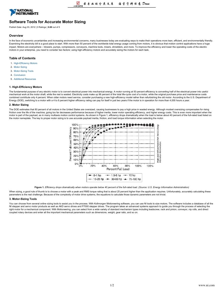
motor is part of the payload, as in many multiaxis motion control systems. As shown in Figure 1, efficiency drops dramatically when the load is below about 40 percent of the full-rated load listed on
the motor nameplate. The key to proper motor sizing is to use accurate payload inertia, friction, and load torque information when selecting the motor.
Figure 1. Efficiency drops dramatically when motors operate below 40 percent of the full-rated load. (Source: U.S. Energy Information Administration)
When sizing, a good rule of thumb is to choose a motor with a peak and RMS torque rating that is about 25 percent higher than the application requires. Unfortunately, accurately calculating these
parameters is the real challenge. Because of the complexity of motor drive systems, the equations to calculate those dynamic parameters are not trivial.
3. Motor-Sizing Tools
You can choose from several online sizing tools to assist you in the process. With Kollmorgen Motioneering software, you can use NI tools to size motors. The software includes a database of all the
NI stepper and servo motor products as well as AKD servo drives and P7000 stepper drives. The program takes an advanced systems approach to guide you through the process of selecting the
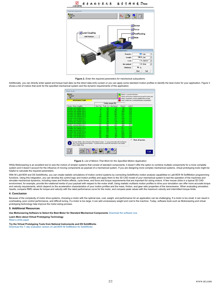
right motor for a mechanical component. With Motioneering, you can select from a wide variety of standard mechanism types including leadscrew, rack and pinion, conveyor, nip rolls, and direct
coupled rotary devices and enter all the important mechanical parameters such as dimensions, weight, gear ratio, and so on.
1/2
www.ni.com
�
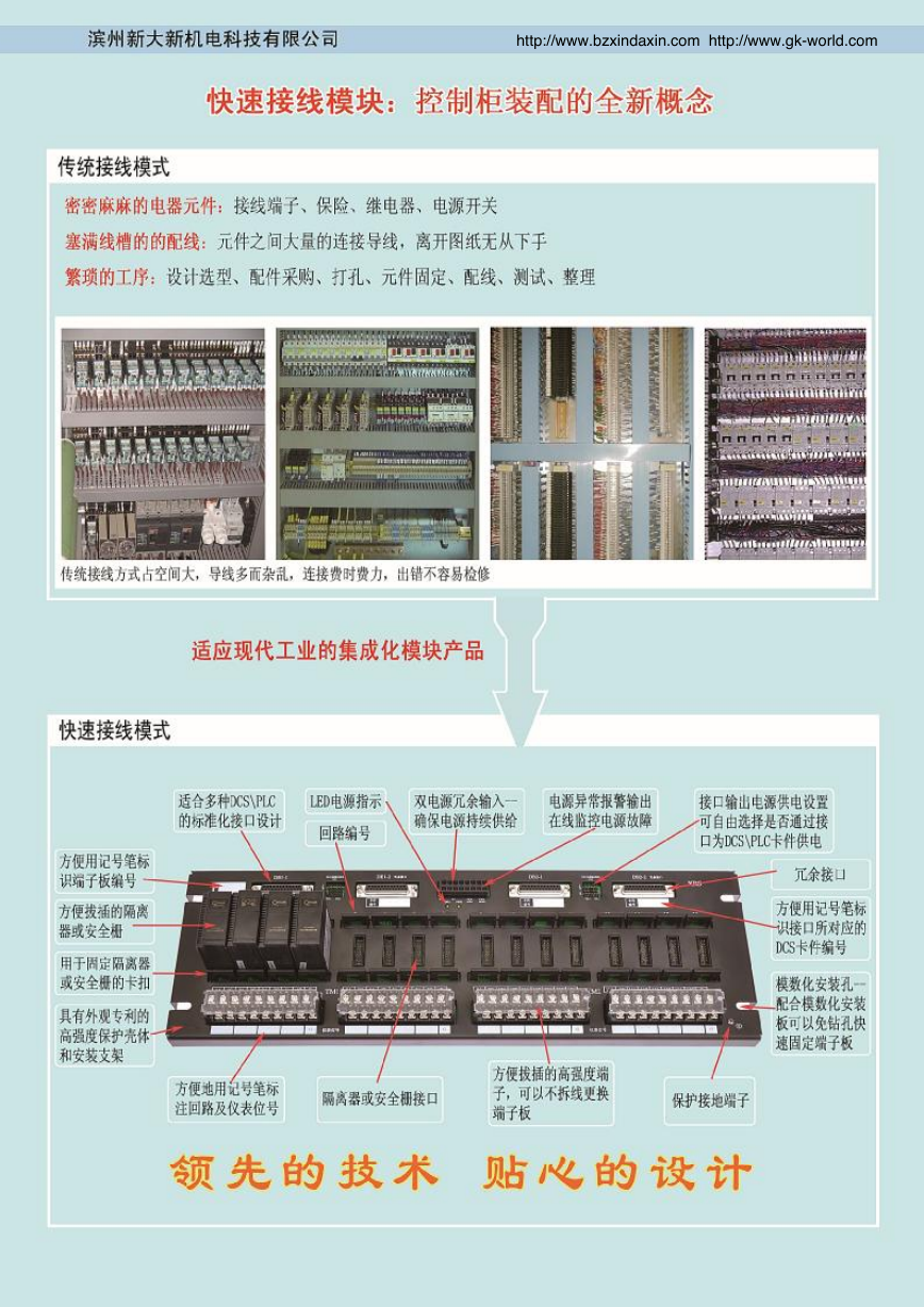
Additionally, you can directly enter speed and torque load data via the direct data entry screen or you can apply some standard motion profiles to identify the best motor for your application. Figure 3
shows a list of motors that work for the specified mechanical system and the dynamic requirements of this application.
Figure 2. Enter the required parameters for mechanical subsystems.
Figure 3. List of Motors That Work for the Specified Motion Application
While Motioneering is an excellent tool to size the motors of simpler systems that consist of standard components, it doesn’t offer the option to combine multiple components for a more complete
system and it doesn’t account for the influence of moving components as payload of a mechanical system. If you are designing more complex mechanical systems, virtual prototyping tools might be
helpful to calculate the required parameters.
With NI LabVIEW and DS SolidWorks, you can create realistic simulations of motion control systems by connecting SolidWorks motion analysis capabilities to LabVIEW NI SoftMotion programming
functions. Using this integration, you can develop the control logic and motion profiles and apply them to the 3D CAD model of your mechanical system to test the operation of the machines and
simulate mechanical dynamics, including mass and friction effects, cycle times, and force and torque requirements that are important for sizing motors. A few mouse clicks in a typical 3D CAD
environment, for example, provide the rotational inertia of your payload with respect to the motor shaft. Using realistic multiaxis motion profiles to drive your simulation can offer more accurate torque
and velocity requirements, which depend on the acceleration characteristics of your motion profiles and the mass, friction, and gear ratio properties of the transmission. When evaluating simulation
results, compare RMS values for torque and velocity with the rated performance curve for the motor, and compare peak values with the maximum velocity and intermittent torque limits.
4. Conclusion
Because of the complexity of motor drive systems, choosing a motor with the optimal size, cost, weight, and performance for an application can be challenging. If a motor is too small, it can result in
overheating, poor control performance, and difficult tuning. If a motor is too large, it can add unnecessary weight and cost to the machine. Today, software tools such as Motioneering and virtual
prototyping technology help improve the motor-sizing process.
5. Additional Resources
Use Motioneering Software to Select the Best Motor for Standard Mechanical Components Download the software now
Learn More about Virtual Prototyping Technology
Read a white paper
Try the Virtual Prototyping Tools from National Instruments and DS SolidWorks
Download the 7–day evaluation version of LabVIEW NI SoftMotion for SolidWorks
2/2
www.ni.com
�
Understanding Servo Tune
out of 5
Publish Date: Jul 09, 2012 | 102 Ratings |
4.22
Overview
Servo systems contain error-driven control loops. Servo tuning is an integral part of any motion system and directly impacts the accuracy and performance. A properly tuned system can provide
higher precision and more stability. This Developer Zone Tutorial will walk through the process to architect an effective set of parameters to best optimize your system for use with our SoftMotion
Software or PCI/PXI boards.
Table of Contents
1.
2.
3.
Part I: Servo Tune Fundamentals
Part II: Tuning Servo Motors
Part III: Advanced Tuning Techniques
1. Part I: Servo Tune Fundamentals
Introduction
Part I of the
control concepts. This section is dedicated to the basics of servo tuning refer to part II and part III for specific systems.
Understanding Servo Tune
document provides information necessary for getting started with tuning servo tune motors. It requires basic knowledge of servo motors, controls, and motion
Part I is divided into the following sections:
Getting Started: Accessing Servo Gain Tuning Panel
PID Control Loop Parameters
Step Response
Stability in the Time Domain
Analyzing the Step Response Plot
GETTING STARTED: ACCESSING SERVO GAIN TUNING
Both the PCI/PXI motion control boards and NI SoftMotion include a gain tuning panel. Depending on your system you will access this through Measurement & Automation Explorer (MAX) or the
LabVIEW project. Use the Gain Tuning Panel to determine the relative stability of a servo system and fine-tune the control loop gains. A system is considered stable if the actual position is finite when
the commanded position is finite. In other words, a system is stable if a commanded position results in the motor coming to rest at a single position. A system is considered unstable when any
commanded position typically results in an exponential increase in position error. In other words, a system is unstable when the attempts to achieve a position result in oscillations that never
dampen.
If your system is a 7340 or 7350 PCI/PXI Board follow these steps to access Servo Tune:
1.
2.
3.
4.
The following figure shows the Servo Tune Step Response interface.
Launch MAX.
Expand the
Expand
Expand
branch on the configuration tree.
PCI/PXI-73xx
Calibration
Devices and Interfaces
Step Response
tab.
Motion Controller.
, and click
Servo Tune
. Select the
1/9
www.ni.com
�
http://www.bzxindaxin.com http://www.gk-world.com
全球独家推出 全覆盖型省配线解决方案
�
http://www.bzxindaxin.com http://www.gk-world.com
�
http://www.bzxindaxin.com http://www.gk-world.com
�
http://www.bzxindaxin.com http://www.gk-world.com
�
�





 2023年江西萍乡中考道德与法治真题及答案.doc
 2012年重庆南川中考生物真题及答案.doc
 2013年江西师范大学地理学综合及文艺理论基础考研真题.doc
 2020年四川甘孜小升初语文真题及答案I卷.doc
 2020年注册岩土工程师专业基础考试真题及答案.doc
 2023-2024学年福建省厦门市九年级上学期数学月考试题及答案.doc
 2021-2022学年辽宁省沈阳市大东区九年级上学期语文期末试题及答案.doc
 2022-2023学年北京东城区初三第一学期物理期末试卷及答案.doc
 2018上半年江西教师资格初中地理学科知识与教学能力真题及答案.doc
 2012年河北国家公务员申论考试真题及答案-省级.doc
 2020-2021学年江苏省扬州市江都区邵樊片九年级上学期数学第一次质量检测试题及答案.doc
 2022下半年黑龙江教师资格证中学综合素质真题及答案.doc