T e c h e l l w
PRELIMINARY
LCD Video Processor with Built-in Decoder, Triple
ADCs, LVDS & TTL Inputs, MCU, OSD, TCON and LVDS
panel interface
TW8836
The TW8836 is a highly integrated LCD video processor
that incorporates many of the features required to
create a multi-purpose LCD display system into a single
package. This includes a high quality 2D comb
NTSC/PAL/SECAM video decoder, triple high speed RGB
ADCs, an LVDS and TTL digital input interface, high
quality scaler and de-interlacer, as well as a versitile
OSD, high performance MCU, and LVDS or TTL output
panel interface. The TW8836 can support input
resolutions up to 1080p and can drive LCD panels at
resolutions up 1366 x 768. The TW8836’s video
processing capability includes arbitrary H/V scaling,
panoramic scaling, image mirroring, image adjustment
and enhancement, black and white stretch, etc. The
feature set and versatility of this device makes it an
ideal solution for in-car LCD display applications, as well
as portable display applications such as Pico Projectors.
Applications
In-car display
Digital horizontal PLL and Advanced synchronization
processing for VCR playback and weak signal
performance
High quality horizontal and vertical filtered down
scaling with arbitrary scale down ratio
Up to 2CH differential or 4CH single ended CVBS input
Analog RGB Inputs
Triple high speed 10-bit ADCs with clamping and
programmable gain amplifier
SOG and H/V sync support for YPbPr or RGB input
Built-in line locked PLL with sync separator
Supports input resolution up to 1080p
Digital Inputs Support
Supports both BT656 and 601 video formats
Supports YCbCr/RGB 24-bit input (bi-directional) up to
1080p resolution
Single channel LVDS input up to 720p resolution
Pico Projector & Portable media player
Supports RGB 565 + BT 656 at the same time
Portable DVD and DVR players
Analog Video Decoder
TFT Panel Support
Built-in programmable timing controller
NTSC (M, 4.43) and PAL (B, D, G, H, I, M, N, N
Supports 3, 4, 6 or 8 bits per pixel up to 16.8 million
combination), PAL (60), SECAM with automatic format
detection
Three 10-bit ADCs and analog clamping circuit.
colors with built-in dithering engine
Supports digital panels (TTL) or single channel LVDS
panels up to WXGA (1366 x 768) resolution, 85MHz
Fully programmable static gain or automatic gain
Supports Serial (8-bit) RGB panel
control for the Y or CVBS channel
Programmable white peak control for the Y or CVBS
Font Based On Screen Display
channel
Software selectable analog inputs allows composite,
S-video, analog YPbPr or RGB
High quality adaptive 2D comb filter for both NTSC
and PAL inputs
PAL delay line for color phase error correction
Image enhancement with 2D dynamic peaking / CTI.
Digital sub-carrier PLL for accurate color decoding
Programmable hue, brightness, saturation, contrast,
sharpness
Selectable differential or single-ended CVBS input
Eight window font OSD with bordering / shadow
10KB programmable font RAM and 512 display RAM
1/2/3/4 bits/pixel
Supports variable width (12/16), height (2~32)
SPI Flash Based On Screen Display
9 bitmap based OSD windows in 2 layers through SPI
with alpha blending between layers
Supports 4/6/8 bits/pixel
Supports RLE decompression for two windows
1
FNXXXX
May 17, 2012
1-888-INTERSIL or 1-888-468-3774 | Copyright Intersil Americas Inc. 2012. All Rights Reserved
Intersil (and design) is a trademark owned by Intersil Corporation or one of its subsidiaries.
All other trademarks mentioned are the property of their respective owners.
�
Image Processing
Miscellaneous
High quality scaler with both up/down and panorama
Supports Fast Mode Plus I2C interface
TW8836
Up to 4 PWMs
GPIOs
1.8/3.3V internal operation
1.8V I/O support
Power-down mode
Single 27MHz crystal
128-pin LQFP with Exposed Thermal Pad and
172 ball TFBGA package
/ water-glass scaling support
Built-in 2D de-interlacing function
Programmable brightness, contrast, saturation, hue
and sharpness
Programmable color transient improvement control
Supports programmable cropping of input video and
graphics
Independent RGB gain and offset controls
DTV hue adjustment
Programmable 8-bit Gamma correction for each color
Black/White Stretch
Clock Generation
Spread spectrum profile based on triangular
modulation with center spread
Programmable modulation frequency and spread
width
Timing Controller (TCON)
Supports programmable interface signals for control
Column (source) driver/Row (gate) driver
MCU
Industry standard 8052 based
Code fetch from external SPI flash memory
256B code cache
2K XDATA memory
Supports power save mode with 32K internal clock
ISP (In System Programming) through I2C
Supports 24-bit addressing
BT.656 Output
Independent ITU-R 656 compatible YCbCr(4:2:2)
output format
Supports progressive ITU-R 656 output format for both
interlaced and progressive inputs
ITU-R 656 output generated from decoder, ARGB,
DRGB and post scaling path
Touch Screen Controller
Built-in 4-wire resistive touch screen
12–bit ADC
4 channel Auxiliary input
2
�
TW8836
Table of Contents
Analog Video Decoder ........................................................................... 1
Analog RGB Inputs................................................................................. 1
Digital Inputs Support ............................................................................ 1
TFT Panel Support .................................................................................. 1
Font Based On Screen Display ............................................................ 1
SPI Flash Based On Screen Display ................................................... 1
Image Processing ................................................................................... 2
Clock Generation .................................................................................... 2
Timing Controller (TCON) ..................................................................... 2
MCU ........................................................................................................... 2
BT.656 Output .......................................................................................... 2
Touch Screen Controller ....................................................................... 2
Miscellaneous .......................................................................................... 2
Table of Contents ............................................................................... 3
Ordering Information ........................................................................ 10
TW8836 Functional Block Diagram................................................. 10
Functional Description ..................................................................... 11
Overview ................................................................................................. 11
Analog Front-end .................................................................................. 11
Video Decoder ....................................................................................... 11
Sync Processor .................................................................................. 11
Horizontal Sync Processing .............................................................. 11
Vertical Sync Processing ................................................................... 11
Color Decoding ................................................................................... 12
Y/C Separation ................................................................................... 12
Color Demodulation ........................................................................... 12
Automatic Chroma Gain Control ....................................................... 12
Low Color Detection and Removal ................................................... 12
Automatic Standard Detection .......................................................... 12
Video Format Support ........................................................................ 13
Component Processing ..................................................................... 13
Luminance Processing ...................................................................... 13
The Hue and Saturation .................................................................... 13
Touch Screen Controller ..................................................................... 13
Digital Input Support ............................................................................ 13
LVDS Video Input Interface ............................................................... 14
Input Image Control .............................................................................. 16
Image Scaling ........................................................................................ 16
Image Enhancement Processing ...................................................... 16
Black/White Stretch ............................................................................ 16
TFT Panel Support ................................................................................ 16
Dithering .............................................................................................. 16
Gamma Table .................................................................................... 16
TCON .................................................................................................. 16
LVDS out put format........................................................................... 16
LVDS Color Mapping ......................................................................... 17
Font Based On Screen Display .......................................................... 18
On Chip OSD functions ..................................................................... 18
Basic Register Setting Flow Example for Built-in OSD Controller.. 19
OSD Window Start Location: Built-in OSD Controller ..................... 21
OSD_RAM Configuration .................................................................... 21
Alpha Blending for OSD Window ..................................................... 22
Alpha Blending Concept .................................................................... 22
SPI Flash On Screen Display.............................................................. 23
Pixel Order .......................................................................................... 26
RLC Data Format ............................................................................... 27
OSD Display Path .............................................................................. 28
Built-in Microcontroller ........................................................................ 30
TW8836 MCU Block Diagram ............................................................. 31
Microcontroller Interface ..................................................................... 31
Two Wire Serial Bus Interface ........................................................... 32
Pin Diagram ...................................................................................... 35
TW8836 128 pin LQFP (Top-View) ................................................ 35
Pin Descriptions ............................................................................... 37
Parametric Information..................................................................... 44
AC/DC Electrical Parameters.............................................................. 44
Package Outline Drawing ................................................................ 50
Q128.14x14: 128 Lead Low Plastic Quad Flatpack Package
(LQFP) 0.4mm pitch.............................................................................. 50
172-pin TFBGA ...................................................................................... 51
3
Filter Curves ..................................................................................... 52
Anti-alias Filter ..................................................................................... 52
Decimation Filter ................................................................................. 52
Chroma Band Pass Filter Curves ..................................................... 53
Luma Notch Filter Curve for NTSC and PAL .................................. 53
Chrominance Low-Pass Filter Curve ............................................... 54
TW8836 Register Summary ............................................................ 55
General ................................................................................................ 55
General ................................................................................................ 55
Input Control ........................................................................................ 55
DTV ..................................................................................................... 56
BT656 Encoder .................................................................................. 56
GPIO.................................................................................................... 56
MBIST (Memory Built-In Test)........................................................... 57
TSC (Touch Screen Control) ............................................................ 57
LOPOR ............................................................................................... 58
SSPLL ................................................................................................. 58
Decoder ............................................................................................... 59
ADC/LLPLL......................................................................................... 61
SCALER / TCON ............................................................................... 63
Image Adjustment .............................................................................. 64
Gamma & Dither ................................................................................ 64
FOSD .................................................................................................. 65
SPI OSD ............................................................................................. 69
SPI & MCU ......................................................................................... 73
MEASUREMENT .............................................................................. 74
LCDC : LVDS .................................................................................... 76
LVDS RX Configuration ..................................................................... 76
MCU Special Function Register ........................................................ 76
TW8836 Register Descriptions ........................................................ 78
0x000 – Product ID Code Register (ID)........................................... 78
0x001 – Product REVISON NUMBER Register ............................ 78
0x002 – IRQ ........................................................................................ 78
0x003 – IMASK .................................................................................. 78
0x004 – Status .................................................................................... 78
0x006 – SRST .................................................................................... 79
0x007 – OUTPUT CTRL I ................................................................. 79
0x008 – OUTPUT CTRL II ................................................................ 80
0x00F – INT0 WRITE PORT ............................................................ 80
0x01F – TEST .................................................................................... 80
INPUT CONTROL ............................................................................. 81
0x040 – INPUT Control I.................................................................... 81
0x041 – INPUT Control II................................................................... 81
0x042 – INPUT CROP_HI ................................................................ 81
0x043 – INPUT V CROP Position .................................................... 81
0x044 – INPUT V CROP Length LO ............................................... 82
0x045 – IINPUT H CROP Position LO ............................................ 82
0x046 – INPUT H CROP Length LO ............................................... 82
0x047 – BT656 Decoder Control I .................................................... 82
0x048 – BT656 Decoder Control II ................................................... 82
0x04B – VSYNC INPUT CONTROL ............................................... 82
0x050 – DTV Input Control ................................................................ 83
0x051 – DTV Input Control ................................................................ 83
0x052 – DTV Input Control ................................................................ 84
0x053 – DTV Input Format ................................................................ 84
0x054 – DTV Field Detection Region ............................................... 85
0x056 – DTV Vsync Delay ................................................................ 85
0x057 – Sequential RGB ................................................................... 85
0x05F – Test Pattern Generator Control Register.......................... 86
0x060 – ENFP2 .................................................................................. 86
0x066 – BT656 Encode Control ....................................................... 86
0x067 – BT656 Encode Control ....................................................... 86
0x068 – BT656 Encode Position_HI ................................................ 87
0x069 – BT656 Encode CROP Length_HI ..................................... 87
0x06A – BT656 ENCODE V CROP Position ................................. 87
0x06B – BT656 ENCODE V CROP Length LO ............................. 87
0x06C – BT656 ENCODE H CROP Position LO .......................... 87
0x06D – BT656 ENCODE H CROP Length LO ............................ 87
0x06E – Vsync PuLSE WIDTH ........................................................ 88
0x06F – HSYNC PULSE WIDTH .................................................... 88
0x080 – GPIO0_EN ........................................................................... 89
0x081 – GPIO1_EN ........................................................................... 89
0x082 – GPIO2_EN ........................................................................... 89
�
TW8836
0x083 – GPIO3_EN ........................................................................... 89
0x084 – GPIO4_EN ........................................................................... 89
0x085 – GPIO5_EN ........................................................................... 89
0x086 – GPIO6_EN ........................................................................... 89
0x088 – GPIO0_OE .......................................................................... 89
0x089 – GPIO1_OE .......................................................................... 90
0x08A – GPIO2_OE .......................................................................... 90
0x08B – GPIO3_OE .......................................................................... 90
0x08C – GPIO4_OE .......................................................................... 90
0x08D – GPIO5_OE .......................................................................... 90
0x08E – GPIO6_OE .......................................................................... 90
0x090 – GPIO0_OD .......................................................................... 90
0x091 – GPIO1_OD .......................................................................... 90
0x092 – GPIO2_OD .......................................................................... 91
0x093 – GPIO3_OD .......................................................................... 91
0x094 – GPIO4_OD .......................................................................... 91
0x095 – GPIO5_OD .......................................................................... 91
0x096 – GPIO6_OD .......................................................................... 91
0x098 – GPIO0_ID ............................................................................ 91
0x099 – GPIO1_ID ............................................................................ 91
0x09A – GPIO2_ID ............................................................................ 91
0x09B – GPIO3_ID ............................................................................ 92
0x09C – GPIO4_ID ............................................................................ 92
0x09D – GPIO5_ID ............................................................................ 92
0x09E – GPIO6_ID ............................................................................ 92
0x0A0 – MBIST Control ..................................................................... 93
0x0A1 – MBIST I ................................................................................ 93
0x0A2 – MBIST II ............................................................................... 93
0x0A3 – MBIST III .............................................................................. 93
0x0A4 – MBIST IV ............................................................................. 93
0x0B0 – Touch Screen Control I ....................................................... 94
0x0B1 – Touch Screen Control II ...................................................... 94
0x0B2 – TSC ADC Data Output_HI ................................................. 94
0x0B3 – TSC ADC Data Output_LO ............................................... 94
0x0B4 – TSC ADC Sample and Clock ............................................ 95
0x0D4 – LOPOR Registers............................................................... 96
0x0D6 – TCLK AND PWM CNTL .................................................... 96
0x0D7 – FPWM3_LO ........................................................................ 96
0x0D8 – DPWM3 ............................................................................... 96
0x0D9 – FPWM4_LO ........................................................................ 96
0x0DA – DPWM4 .............................................................................. 96
0x0DB – FPWM_HI ........................................................................... 97
0x0DC – FPWM1_LO ....................................................................... 97
0x0DD – DPWM1 .............................................................................. 97
0x0DE – FPWM2_LO ....................................................................... 97
0x0DF – DPWM2 ............................................................................... 97
0x0F6 – CLOCK_DIV ........................................................................ 98
0x0F7 – SSPLL .................................................................................. 98
0x0F8 – SSPLL Control Registers ................................................... 98
0x0F9 – SSPLL Frequency Control Registers ................................ 98
0x0FA – SSPLL Frequency Control Registers................................ 98
0x0FB – SSPLL Modulation Frequency Control Registers............ 98
0x0FC – SSPLL ................................................................................. 99
0x0FD – SSPLL Analog Control Registers ...................................... 99
Decoder ............................................................................................. 100
0x101 – Chip Status Register (CSTATUS) ................................... 100
0x102 – Input Format (INFORM) .................................................... 100
0x104 – HSYNC Delay Control ...................................................... 101
0x105 – Output Control Register II .............................................. 101
0x106 – Analog Control Register (ACNTL) ................................... 102
0x107 – Cropping Register, High (CROP_HI) .............................. 102
0x108 – Vertical Delay Register, Low (VDELAY_LO) .................. 102
0x109 – Vertical Active Register, Low (VACTIVE_LO) ................ 102
0x10A – Horizontal Delay Register, Low (HDELAY_LO) ............ 103
0x10B – Horizontal Active Register, Low (HACTIVE_LO) ........... 103
0x10C – Control Register I (CNTRL1) ........................................... 103
0x10D – CC/WSS Control............................................................... 103
0x110 – BRIGHTNESS Control Register (BRIGHT) ................... 104
0x111 – CONTRAST Control Register (CONTRAST) ................ 104
0x112 – SHARPNESS Control Register I (SHARPNESS) ......... 104
0x113 – Chroma (U) Gain Register (SAT_U) ............................... 104
0x114 – Chroma (V) Gain Register (SAT_V) ................................ 104
0x115 – Hue Control Register (HUE) ............................................. 105
4
0x117 – Vertical Peaking Control I .................................................. 105
0x118 – Coring Control Register (CORING) ................................. 105
0x11A – CC/EDS Status Register (CC_STATUS) ....................... 105
0x11B – CC/EDS Data Register (CC_DATA) .............................. 106
0x11C – Standard Selection (SDT) ................................................ 106
0x11D – Standard Recognition (SDTR) ........................................ 106
0x11E – Component Video Format (CVFMT) .............................. 107
0x120 – Clamping Gain (CLMPG) ................................................. 107
0x121 – Individual AGC Gain (IAGC) ............................................. 107
0x122 – AGC Gain (AGCGAIN) ..................................................... 107
0x123 – White Peak Threshold (PEAKWT) .................................. 107
0x125– Sync Amplitude (SYNCT) .................................................. 108
0x126 – Sync Miss Count Register (MISSCNT) ........................... 108
0x127 – Clamp Position Register (PCLAMP) ............................... 108
0x128 – Vertical Control I ................................................................. 108
0x129 – Vertical Control II ................................................................ 108
0x12A – Color Killer Level Control .................................................. 109
0x12B – Comb Filter Control ........................................................... 109
0x12C – Luma Delay and HFilter Control ...................................... 109
0x12D – Miscellaneous Control Register I (MISC1) ..................... 109
0x12E – Miscellaneous Control Register II (MISC2) ..................... 110
0x12F – Miscellaneous Control III (MISC3) ................................... 110
0x131 – Chip STATUS II (CSTATUS2) ......................................... 111
0x132 – H Monitor (HFREF) ........................................................... 111
0x133 – CLAMP MODE(CLMD) .................................................... 111
0x134 – ID Detection Control (NSEN/SSEN/PSEN/WKTH) ....... 111
0x135 – Clamp Control (CLCNTL) ................................................. 112
0x136 – DE-INTERLACER CONTROL............................................. 112
0x137 – DE-INTERLACER H DELAY CONTROL ............................ 112
0x138 – DE-INTERLACER SYNC GENERATION ........................... 112
0x140 – WSS0 ................................................................................. 112
0x141 – WSS1 ................................................................................. 113
0x142 – WSS2 ................................................................................. 113
ADC/LLPLL Configuration Registers.............................................. 114
0x1C0 – LLPLL Input Control Register .......................................... 114
0x1C1 – LLPLL Input Detection Register....................................... 114
0x1C2 – LLPLL Control Register .................................................... 115
0x1C3 – LLPLL Divider High Register ........................................... 115
0x1C4 – LLPLL Divider Low Register ............................................ 115
0x1C5 – LLPLL Clock Phase Register .......................................... 115
0x1C6 – LLPLL Loop Control Register .......................................... 116
0x1C7 – LLPLL VCO Control Register .......................................... 116
0x1C8 – LLPLL VCO Control Register .......................................... 116
0x1C9 – LLPLL Pre Coast Register ............................................... 116
0x1CA – LLPLL Post Coast Register ............................................. 116
0x1CB – SOG Threshold Register ................................................. 117
0x1CC – Scaler Sync Selection Register....................................... 117
0x1CD – PLL Initialization Register ................................................. 117
0x1D0 – Clamp Gain Control Register ........................................... 118
0x1D1 – Y Channel Gain Adjust Register...................................... 118
0x1D2 – C Channel Gain Adjust Register ..................................... 118
0x1D3 – V Channel Gain Adjust Register...................................... 118
0x1D4 – Clamp Mode Control Register ......................................... 118
0x1D5 – Clamp Start Position Register .......................................... 119
0x1D6 – Clamp Stop Position Register .......................................... 119
0x1D7 – Clamp Master Location Register ..................................... 119
0x1D8 – ADC TEST Register ......................................................... 119
0x1D9 – Y Clamp Reference Register ........................................... 119
0x1DA – C Clamp Reference Register .......................................... 119
0x1DB – V Clamp Reference Register .......................................... 119
0x1DC ............................................................................................... 120
0x1E0 – LLPLL Control Register .................................................... 120
0x1E1 – LLPLL Control Register .................................................... 120
0x1E2 – ADC Control I .................................................................... 121
0x1E3 – ADC Control II ................................................................... 121
0x1E4 – ADC Control III .................................................................. 121
0x1E5 – ADC Control IV .................................................................. 122
0x1E6 – ADC Control V ................................................................... 122
0x1E7 – ADC Control VI .................................................................. 122
0x1E8 – ADC Control VII ................................................................ 123
0x1E9 – CLOCK CONTROL ............................................................. 123
0x1EA – CLOCK CONTROL II .......................................................... 123
0x1F6 – DIFFERENTIAL CLAMP CONTROL I ................................ 124
�
TW8836
0x1F7 – DIFFERENTIAL CLAMP CONTROL II ............................... 124
0x1F8 – DIFFERENTIAL CLAMP CONTROL III ............................. 124
0x1F9 – DIFFERENTIAL CLAMP CONTROL IV ............................. 125
0x1FA – DIFFERENTIAL CLAMP CONTROL V .............................. 125
SCALER ........................................................................................... 126
0x201 – General Scaler Control ...................................................... 126
0x202– Scaling Offset Control......................................................... 126
0x203– XSCALE_LO ...................................................................... 126
0x204– XSCALE_HI ........................................................................ 126
0x205– YSCALE_LO ...................................................................... 126
0x206– YSCALE_HI ........................................................................ 127
0x207– PXSCALE ........................................................................... 127
0x208– PXINC ................................................................................. 127
0x209– HDSCALE_LO ................................................................... 127
0x20A– HDSCALE_HI .................................................................... 127
0x20B– HDELAY2 ........................................................................... 127
0x20C– HACTIVE2_LO .................................................................. 128
0x20D– LNTT_HI ............................................................................. 128
0x20E– HPADJ_HI .......................................................................... 128
0x20F– HPADJ_LO ......................................................................... 128
0x210– HA_POS_LO ...................................................................... 128
0x211– HA_LEN_LO ...................................................................... 129
0x212– HA_LEN_HI ........................................................................ 129
0x213– HS_POS ............................................................................. 129
0x214– HS_LEN .............................................................................. 129
0x215– VA_POS.............................................................................. 129
0x216– VA_LEN_LO ....................................................................... 129
0x217– VA_LEN_HI ........................................................................ 129
0x218– VS_LEN_POS.................................................................... 130
0x219– LNTT_LO ............................................................................ 130
0x21A– DM_TOP ............................................................................ 130
0x21B– DM_BOT ............................................................................ 130
0x21C– PANEL_FRUN .................................................................. 130
0x21D– HTOTAL_LO ..................................................................... 130
0x21E– BLANK ................................................................................ 131
0x220– VA_VS_POS ....................................................................... 131
0x221– HA_HS_POS ....................................................................... 131
TCON ................................................................................................ 132
0x240– CSP Control ........................................................................ 132
0x241– CLP Position ....................................................................... 132
0x242– CLP Width ........................................................................... 132
0x243– RCK Control HI ................................................................... 132
0x244– RCK Position LO ................................................................ 132
0x245– RCK Width LO .................................................................... 132
0x246– ROE Control HI ................................................................... 133
0x247– ROE Position LO ................................................................ 133
0x248– ROE Width LO .................................................................... 133
0x249– RSP Control ........................................................................ 133
0x24A– RSP Position Control ......................................................... 133
0x24B– CPL Position Control ......................................................... 134
0x24C– CPL Position Control LO ................................................... 134
0x24D– TCON Control I .................................................................. 134
0x24E– TCON Control II ................................................................. 135
IMAGE ENHANCEMENT .............................................................. 136
0x280 – Image Adjustment Register .............................................. 136
0x281 – Image Adjustment Register .............................................. 136
0x282 – Image Adjustment Register .............................................. 136
0x283 – Image Adjustment Register .............................................. 136
0x284 – Image Adjustment Register .............................................. 136
0x285 – Image Adjustment Register .............................................. 136
0x286 – Image Adjustment Register .............................................. 136
0x287 – Image Adjustment Register .............................................. 137
0x288 – Image Adjustment Register .............................................. 137
0x289 – Image Adjustment Register .............................................. 137
0x28A – Image Adjustment Register.............................................. 137
0x28B – Image Adjustment Register.............................................. 137
0x28C – Image Adjustment Register ............................................. 137
0x2B0 – Image Adjustment Register.............................................. 138
0x2B1 – Image Adjustment Register.............................................. 138
0x2B2 – Image Adjustment Register.............................................. 138
0x2B6 – Image Adjustment Register.............................................. 138
0x2B7 – Image Adjustment Register.............................................. 138
0x2BE – Image Adjustment Register ............................................. 138
5
0x2BF – Test Pattern Generator Register ..................................... 139
0x2E0 – LCDC Gamma Control Register ..................................... 140
0x2E1 – Gamma Table Address Port Register............................. 140
0x2E3 – Gamma Table Data Port Register ................................... 140
0x2E4 – Dither Option Register ...................................................... 141
Dither Output Selection and Calculations ....................................... 141
0x2F0 – RGB Level Readout Register .......................................... 142
0x2F1 – RGB Level Readout Register .......................................... 142
0x2F2 – RGB Level Readout Register .......................................... 142
0x2F3 – RGB Level Readout Register .......................................... 142
0x2F4 – RGB Level Readout Register .......................................... 142
0x2F5 – RGB Level Readout Register .......................................... 142
0x2F8 – 8-bit Panel Interface Register ........................................... 143
0x2F9 – 8-bit Panel Interface Register ........................................... 143
FOSD ................................................................................................ 144
0x300 – Font OSD Control Register............................................... 144
0x301 – Status Register .................................................................. 144
0x302 – Test Register ...................................................................... 144
0x303 – Font OSD Control Register............................................... 144
0x304 – Font OSD Control Register............................................... 145
0x305 – Font OSD Control Register............................................... 145
0x306 – OSD RAM Address Register ........................................... 145
0x307 – OSD RAM Data Port Hi Register ..................................... 145
0x308 – OSD RAM Data Port Lo Register .................................... 145
0x309 – Font RAM Address Register ............................................ 146
0x30A – Font RAM Data Port ......................................................... 146
0x30B – Multi-Color Font Start Position Register .......................... 146
0x30C – Font OSD Control Register .............................................. 146
0x30D – Character Color Look-up table data port High Byte
Register ............................................................................................. 146
0x30E – Character Color Look-up table data port Low Byte
Register ............................................................................................. 146
0x310 – OSD Window1 Control Register ...................................... 147
0x311 – OSD Window1 Control Register ...................................... 147
0x312 – OSD Window1 Control Register ...................................... 147
0x313 – OSD Window1 Control Register ...................................... 147
0x314 – OSD Window1 Control Register ...................................... 147
0x315 – OSD Window1 Control Register ...................................... 147
0x316 – OSD Window1 Control Register ..................................... 148
0x317 – OSD Window1 Control Register ...................................... 148
0x318 – OSD Window1 Control Register ...................................... 148
0x319 – OSD Window1 Control Register ...................................... 148
0x31A – OSD Window1 Control Register ..................................... 148
0x31B – OSD Window1 Control Register ..................................... 148
0x31C – OSD Window1 Control Register ..................................... 149
0x31D – OSD Window1 Control Register .................................... 149
0x31E – OSD Window1 Control Register ..................................... 149
0x31F – OSD Window1 Control Register ...................................... 149
0x320 – OSD Window2 Control Register ...................................... 149
0x321 – OSD Window2 Control Register ...................................... 149
0x322 – OSD Window2 Control Register ...................................... 150
0x323 – OSD Window2 Control Register ...................................... 150
0x324 – OSD Window2 Control Register ...................................... 150
0x325 – OSD Window2 Control Register ...................................... 150
0x326 – OSD Window2 Control Register ...................................... 150
0x327 – OSD Window2 Control Register ...................................... 150
0x328 – OSD Window2 Control Register ...................................... 151
0x329 – OSD Window2 Control Register ...................................... 151
0x32A – OSD Window2 Control Register ..................................... 151
0x32B – OSD Window2 Control Register ..................................... 151
0x32C – OSD Window2 Control Register ..................................... 151
0x32D – OSD Window2 Control Register ..................................... 151
0x32E – OSD Window2 Control Register ..................................... 152
0x32F – OSD Window2 Control Register ...................................... 152
0x330 – OSD Window3 Control Register ...................................... 152
0x331 – OSD Window3 Control Register ...................................... 152
0x332 – OSD Window3 Control Register ...................................... 152
0x333 – OSD Window3 Control Register ...................................... 152
0x334 – OSD Window3 Control Register ...................................... 153
0x335 – OSD Window3 Control Register ...................................... 153
0x336 – OSD Window3 Control Register ...................................... 153
0x337 – OSD Window3 Control Register ...................................... 153
0x338 – OSD Window3 Control Register ...................................... 153
�
TW8836
0x339 – OSD Window3 Control Register ...................................... 153
0x33A – OSD Window3 Control Register ..................................... 154
0x33B – OSD Window3 Control Register ..................................... 154
0x33C – OSD Window3 Control Register ..................................... 154
0x33D – OSD Window3 Control Register ..................................... 154
0x33E – OSD Window3 Control Register ..................................... 154
0x33F – OSD Window3 Control Register ...................................... 154
0x340 – OSD Window4 Control Register ...................................... 155
0x341 – OSD Window4 Control Register ...................................... 155
0x342 – OSD Window4 Control Register ...................................... 155
0x343 – OSD Window4 Control Register ...................................... 155
0x344 – OSD Window4 Control Register ...................................... 155
0x345 – OSD Window4 Control Register ...................................... 155
0x346 – OSD Window4 Control Register ...................................... 156
0x347 – OSD Window4 Control Register ...................................... 156
0x348 – OSD Window4 Control Register ...................................... 156
0x349 – OSD Window4 Control Register ...................................... 156
0x34A – OSD Window4 Control Register ..................................... 156
0x34B – OSD Window4 Control Register ..................................... 156
0x34C – OSD Window4 Control Register ..................................... 157
0x34D – OSD Window4 Control Register ..................................... 157
0x34E – OSD Window4 Control Register ..................................... 157
0x34F – OSD Window4 Control Register ...................................... 157
0x350 – OSD Window5 Control Register ................................... 157
0x351 – OSD Window5 Control Register ................................... 157
0x352 – OSD Window5 Control Register ................................... 158
0x353 – OSD Window5 Control Register ................................... 158
0x354 – OSD Window5 Control Register ................................... 158
0x345 – OSD Window4 Control Register ................................... 158
0x356 – OSD Window5 Control Register ................................... 158
0x357 – OSD Window5 Control Register ................................... 158
0x358 – OSD Window5 Control Register ................................... 159
0x359 – OSD Window5 Control Register ................................... 159
0x35A – OSD Window5 Control Register ................................... 159
0x35B – OSD Window5 Control Register ................................... 159
0x35C – OSD Window5 Control Register ................................... 159
0x35D – OSD Window5 Control Register ................................... 160
0x35E – OSD Window5 Control Register ................................... 160
0x35F – OSD Window5 Control Register .................................... 160
0x360 – OSD Window6 Control Register ................................... 160
0x361 – OSD Window6 Control Register ................................... 160
0x362 – OSD Window6 Control Register ................................... 160
0x363 – OSD Window6 Control Register ................................... 161
0x364 – OSD Window6 Control Register ................................... 161
0x365 – OSD Window6 Control Register ................................... 161
0x366 – OSD Window6 Control Register ................................... 161
0x367 – OSD Window6 Control Register ................................... 161
0x368 – OSD Window6 Control Register ................................... 161
0x369 – OSD Window6 Control Register ................................... 162
0x36A – OSD Window6 Control Register ................................... 162
0x36B – OSD Window6 Control Register ................................... 162
0x36C – OSD Window6 Control Register ................................... 162
0x36D – OSD Window6 Control Register ................................... 162
0x36E – OSD Window6 Control Register ................................... 162
0x36F – OSD Window6 Control Register .................................... 163
0x370 – OSD Window7 Control Register ................................... 163
0x371 – OSD Window7 Control Register ................................... 163
0x372 – OSD Window7 Control Register ................................... 163
0x373 – OSD Window7 Control Register ................................... 163
0x374 – OSD Window7 Control Register ................................... 163
0x375 – OSD Window7 Control Register ................................... 164
0x376 – OSD Window7 Control Register ................................... 164
0x377 – OSD Window7 Control Register ................................... 164
0x378 – OSD Window7 Control Register ................................... 164
0x379 – OSD Window7 Control Register ................................... 164
0x37A – OSD Window7 Control Register ................................... 164
0x37B – OSD Window7 Control Register ................................... 165
0x37C – OSD Window7 Control Register ................................... 165
0x37D – OSD Window7 Control Register ................................... 165
0x37E – OSD Window7 Control Register ................................... 165
0x37F – OSD Window7 Control Register .................................... 165
0x380 – OSD Window8 Control Register ................................... 166
0x381 – OSD Window8 Control Register ................................... 166
6
0x382 – OSD Window8 Control Register ................................... 166
0x383 – OSD Window8 Control Register ................................... 166
0x384 – OSD Window8 Control Register ................................... 166
0x385 – OSD Window8 Control Register ................................... 166
0x386 – OSD Window8 Control Register ................................... 167
0x387 – OSD Window8 Control Register ................................... 167
0x388 – OSD Window8 Control Register ................................... 167
0x389 – OSD Window8 Control Register ................................... 167
0x38A – OSD Window8 Control Register ................................... 167
0x38B – OSD Window8 Control Register ................................... 167
0x38C – OSD Window8 Control Register ................................... 168
0x38D – OSD Window8 Control Register ................................... 168
0x38E – OSD Window8 Control Register ................................... 168
0x38F – OSD Window8 Control Register .................................... 168
0x390 – Font OSD Control Register .............................................. 169
0x391 – Font OSD Control Register .............................................. 169
0x392 – Font OSD Control Register .............................................. 169
0x393 – Multi-Color Font Start Position Register ........................... 169
0x394 – Multi-Color Font Start Position Register ........................... 169
SPI OSD ........................................................................................... 170
0x400 – SPIOSD Control Register ................................................. 170
0x404 ~ 0x407 – SPIOSD RLC Register ...................................... 170
0x404 – SPIOSD RLC Control ....................................................... 170
0x405 – SPIOSD RLC Configuration ............................................ 170
0x406 – SPIOSD RLC Window Select .......................................... 171
0x407 – SPIOSD RLC_B Configuration ....................................... 171
0x40E ~ 0x40F – SPIOSD TIME Adjust Register......................... 171
0x40E High Byte ............................................................................... 171
0x40F High Byte ............................................................................... 171
0x410 – 8-Bit SPIOSD Look Up Table Access Control Register 172
0x411 – 8 Bit SPIOSD Look Up Table Address [7:0] Register .... 172
0x412 – 8 Bit SPIOSD Look Up Table Data Port [7:0] Register .. 172
0x420 – SPIOSD Window 0 Enable Register ............................... 173
0x421 ~ 0x423 – SPIOSD Window 0 Horizontal/Vertical Start
Registers ........................................................................................... 173
0x421 – Horizontal/Vertical High Byte Register ............................. 173
0x422 – Horizontal Low Byte Register ........................................... 173
0x423 – Vertical Low Byte Register ................................................ 173
0x424~0x0426 – SPIOSD Window 0 Horizontal/Vertical Length
Registers ........................................................................................... 174
0x0424 – Horizontal/Vertical High Byte Register ........................... 174
0x425 – Horizontal Low Byte Register ........................................... 174
0x426 – Vertical Low Byte Register ................................................ 174
0x427 – 0x429 SPIOSD Window 0 Buffer Memory Starting
Address [23:0] Register ................................................................... 174
0x427 – High Byte Register ............................................................. 174
0x428 – Mid byte Register ............................................................... 174
0x429 – Low Byte Register ............................................................. 174
0x42A~0x42C – SPIOSD Window 0 Buffer Horizontal/Vertical
Length [11:0] Registers .................................................................... 175
0x42A – Horizontal/Vertical High Byte Register ............................ 175
0x42B – Horizontal Low Byte Register ........................................... 175
0x42C – Vertical Low Byte Register ............................................... 175
0x42D~0x42F – SPIOSD Window 0 Image Horizontal/Vertical Start
Registers ........................................................................................... 175
0x42D – Horizontal/Vertical High Byte Register ............................ 175
0x42E – Low byte Register ............................................................. 175
0x42F – Low Byte Register ............................................................. 175
0x430 – SPIOSD Window 0 Global Alpha Value [6:0] Register .. 176
0x431 – SPIOSD Window 0 LUT Pointer Offset Register ........... 176
0x432~0x435 – SPIOSD Window 0 Loop Control Registers ...... 176
0x432 – Looping Horizontal Frame Number Register .................. 176
0x433 – Looping Vertical Frame Number Register ...................... 176
0x434 – Frame Duration Register .................................................. 176
0x435 – SPIOSD Window 0 Loop Enable Register ..................... 177
0x436 – SPIOSD Window 0 Fill Color Register ............................ 177
0x440 – SPIOSD Window 1 Enable Register ............................... 177
0x441~ 0x443 – SPIOSD Window 1 Horizontal/Vertical Start
Registers ........................................................................................... 177
0x441 – Horizontal/Vertical High Byte Register ............................. 177
0x442 – Horizontal Low Byte Register ........................................... 178
0x443 – Vertical Low Byte Register ................................................ 178
�
TW8836
0x444~0x446 – SPIOSD Window 1 Horizontal/Vertical Length
Registers ........................................................................................... 178
0x444 – Horizontal/Vertical High Byte Register ............................. 178
0x445 – Horizontal Low Byte Register ........................................... 178
0x446 – Vertical Low Byte Register ................................................ 178
0x447~0x044A – SPIOSD Window 1 Buffer Memory Starting
Address [23:0] Registers.................................................................. 178
0x0447 – High Byte Register .......................................................... 178
0x448 – Mid Byte Register .............................................................. 179
0x449 – Low Byte Register ............................................................. 179
0x44A – Low Byte Bit Register........................................................ 179
0x44A~0x44B – SPIOSD Window 1 Buffer Horizontal Length [11:0]
Registers ........................................................................................... 179
0x44A – High Byte Register ............................................................ 179
0x44B – Low Byte Register ............................................................. 179
0x44C – SPIOSD Window 1 Global Alpha Value [6:0] Register . 179
0x44D – SPIOSD Window 1 LUT Pointer Offset Register........... 180
0x44E – SPIOSD Window 1 Fill Color Register ............................ 180
0x450 – SPIOSD Window 2 Enable Register ............................... 180
0x451~ 0x453 – SPIOSD Window 2 Horizontal/Vertical Start
Registers ........................................................................................... 180
0x451 – Horizontal/Vertical High Byte Register ............................. 180
0x452 – Horizontal Low Byte Register ........................................... 181
0x453 – Vertical Low Byte Register ................................................ 181
0x454~0x456 – SPIOSD Window 2 Horizontal/Vertical Length
Registers ........................................................................................... 181
0x454 – Horizontal/ Vertical High Byte Register ............................ 181
0x455 – Horizontal Low Byte Register ........................................... 181
0x456 – Vertical Low Byte Register ................................................ 181
0x457~0x045A – SPIOSD Window 2 Buffer Memory Starting
Address [23:0] Registers.................................................................. 181
0x0457 – High Byte Register .......................................................... 181
0x458 – Mid Byte Register .............................................................. 182
0x459 – Low Byte Register ............................................................. 182
0x45A – Low Byte Register ............................................................. 182
0x45A~0x45B – SPIOSD Window 2 Buffer Horizontal Length [11:0]
Registers ........................................................................................... 182
0x45A – High Byte Register ............................................................ 182
0x45B – Low Byte Register ............................................................. 182
0x45C – SPIOSD Window 2 Global Alpha Value [6:0] Register . 182
0x45D – SPIOSD Window 2 LUT Pointer Offset Register........... 183
0x45E – SPIOSD Window 2 Fill Color Register ............................ 183
0x460 – SPIOSD Window 3 Enable Register ............................... 183
0x461~ 0x463 – SPIOSD Window 3 Horizontal/Vertical Start
Registers ........................................................................................... 183
0x461 – Horizontal/Vertical High Byte Register ............................. 183
0x462 – Horizontal Low Byte Register ........................................... 184
0x463 – Vertical Low Byte Register ................................................ 184
0x464~0x466 – SPIOSD Window 3 Horizontal/Vertical Length
Registers ........................................................................................... 184
0x464 – Horizontal/ Vertical High Byte Register ............................ 184
0x465 – Horizontal Low Byte Register ........................................... 184
0x466 – Vertical Low Byte Register ................................................ 184
0x467~0x046A – SPIOSD Window 3 Buffer Memory Starting
Address [23:0] Registers.................................................................. 184
0x0467 – High Byte Register .......................................................... 184
0x468 – Mid Byte Register .............................................................. 185
0x469 – Low Byte Register ............................................................. 185
0x46A – Low Byte Bit Register........................................................ 185
0x46A~0x46B – SPIOSD Window 3 Buffer Horizontal Length [11:0]
Registers ........................................................................................... 185
0x46A – High Byte Register ............................................................ 185
0x46B – Low Byte Register ............................................................. 185
0x46C – SPIOSD Window 3 Global Alpha Value [6:0] Register . 185
0x46D – SPIOSD Window 3 LUT Pointer Offset Register........... 186
0x46E – SPIOSD Window 3 Fill Color Register ............................ 186
0x470 – SPIOSD Window 4 Enable Register ............................... 186
0x471~ 0x473 – SPIOSD Window 4 Horizontal/Vertical Start
Registers ........................................................................................... 186
0x471 – Horizontal/Vertical High Byte Register ............................. 186
0x472 – Horizontal Low Byte Register ........................................... 187
0x473 – Vertical Low Byte Register ................................................ 187
7
0x474~0x476 – SPIOSD Window 4 Horizontal/Vertical Length
Registers ........................................................................................... 187
0x474 – Horizontal/ Vertical High Byte Register ............................ 187
0x475 – Horizontal Low Byte Register ........................................... 187
0x476 – Vertical Low Byte Register ................................................ 187
0x477~0x0479 – SPIOSD Window 4 Buffer Memory Starting
Address [23:0] Registers.................................................................. 187
0x0477 – High Byte Register .......................................................... 187
0x478 – Mid Byte Register .............................................................. 188
0x479 – Low Byte Register ............................................................. 188
0x47A – Low Byte Bit Register........................................................ 188
0x47A~0x47B – SPIOSD Window 4 Buffer Horizontal Length [11:0]
Registers ........................................................................................... 188
0x47A – High Byte Register ............................................................ 188
0x47B – Low Byte Register ............................................................. 188
0x47C – SPIOSD Window 4 Global Alpha Value [6:0] Register . 188
0x47D – SPIOSD Window 4 LUT Pointer Offset Register........... 189
0x47E – SPIOSD Window 4 Fill Color Register ............................ 189
0x480 – SPIOSD Window 5 Enable Register ............................... 189
0x481~ 0x483 – SPIOSD Window 5 Horizontal/Vertical Start
Registers ........................................................................................... 189
0x481 – Horizontal/Vertical High Byte Register ............................. 189
0x482 – Horizontal Low Byte Register ........................................... 189
0x483 – Vertical Low Byte Register ................................................ 190
0x484~0x486 – SPIOSD Window 5 Horizontal/Vertical Length
Registers ........................................................................................... 190
0x484 – Horizontal/ Vertical High Byte Register ............................ 190
0x485 – Horizontal Low Byte Register ........................................... 190
0x486 – Vertical Low Byte Register ................................................ 190
0x487~0x048A – SPIOSD Window 5 Buffer Memory Starting
Address [23:0] Registers.................................................................. 190
0x0487 – High Byte Register .......................................................... 190
0x488 – Mid Byte Register .............................................................. 190
0x489 – Low Byte Register ............................................................. 191
0x48A – Low Byte Bit Register........................................................ 191
0x48A~0x48B – SPIOSD Window 5 Buffer Horizontal Length [11:0]
Registers ........................................................................................... 191
0x48A – High Byte Register ............................................................ 191
0x48B – Low Byte Register ............................................................. 191
0x48C – SPIOSD Window 5 Global Alpha Value [6:0] Register . 191
0x48D – SPIOSD Window 5 LUT Pointer Offset Register........... 191
0x48E – SPIOSD Window 5 Fill Color Register ............................ 192
0x490 – SPIOSD Window 6 Enable Register ............................... 192
0x491~ 0x493 – SPIOSD Window 6 Horizontal/Vertical Start
Registers ........................................................................................... 192
0x491 – Horizontal/Vertical High Byte Register ............................. 192
0x492 – Horizontal Low Byte Register ........................................... 192
0x493 – Vertical Low Byte Register ................................................ 192
0x494~0x496 – SPIOSD Window 6 Horizontal/Vertical Length
Registers ........................................................................................... 193
0x494 – Horizontal/ Vertical High Byte Register ............................ 193
0x495 – Horizontal Low Byte Register ........................................... 193
0x496 – Vertical Low Byte Register ................................................ 193
0x497~0x049A – SPIOSD Window 6 Buffer Memory Starting
Address [23:0] Registers.................................................................. 193
0x0497 – High Byte Register .......................................................... 193
0x498 – Mid Byte Register .............................................................. 193
0x499 – Low Byte Register ............................................................. 193
0x49A – Low Byte Bit Register........................................................ 193
0x49A~0x49B – SPIOSD Window 6 Buffer Horizontal Length [11:0]
Registers ........................................................................................... 194
0x49A – High Byte Register ............................................................ 194
0x49B – Low Byte Register ............................................................. 194
0x49C – SPIOSD Window 6 Global Alpha Value [6:0] Register . 194
0x49D – SPIOSD Window 6 LUT Pointer Offset Register........... 194
0x49E – SPIOSD Window 6 Fill Color Register ............................ 194
0x4A0 – SPIOSD Window 7 Enable Register .............................. 195
0x4A1~ 0x4A3 – SPIOSD Window 7 Horizontal/Vertical Start
Registers ........................................................................................... 195
0x4A1 – Horizontal/Vertical High Byte Register ............................ 195
0x4A2 – Horizontal Low Byte Register ........................................... 195
0x4A3 – Vertical Low Byte Register ............................................... 195
�
TW8836
0x4A4~0x4A6 – SPIOSD Window 7 Horizontal/Vertical Length
Registers ........................................................................................... 196
0x4A4 – Horizontal/ Vertical High Byte Register ........................... 196
0x4A5 – Horizontal Low Byte Register ........................................... 196
0x4A6 – Vertical Low Byte Register ............................................... 196
0x4A7~0x04AA – SPIOSD Window 7 Buffer Memory Starting
Address [23:0] Registers.................................................................. 196
0x04A7 – High Byte Register .......................................................... 196
0x4A8 – Mid Byte Register .............................................................. 196
0x4A9 – Low Byte Register ............................................................. 196
0x4AA – Low Byte Bit Register ....................................................... 196
0x4AA~0x4AB – SPIOSD Window 7 Buffer Horizontal Length
[11:0] Registers ................................................................................. 197
0x4AA – High Byte Register ............................................................ 197
0x4AB – Low Byte Register ............................................................ 197
0x4AC – SPIOSD Window 7 Global Alpha Value [6:0] Register . 197
0x4AD – SPIOSD Window 7 LUT Pointer Offset Register .......... 197
0x4AE – SPIOSD Window 7 Fill Color Register ........................... 197
0x4B0 – SPIOSD Window 8 Enable Register .............................. 198
0x4B1~ 0x4B3 – SPIOSD Window 8 Horizontal/Vertical Start
Registers ........................................................................................... 198
0x4B1 – Horizontal/Vertical High Byte Register ............................ 198
0x4B2 – Horizontal Low Byte Register ........................................... 198
0x4B3 – Vertical Low Byte Register ............................................... 198
0x4B4~0x4B6 – SPIOSD Window 8 Horizontal/Vertical Length
Registers ........................................................................................... 199
0x4B4 – Horizontal/ Vertical High Byte Register ........................... 199
0x4B5 – Horizontal Low Byte Register ........................................... 199
0x4B6 – Vertical Low Byte Register ............................................... 199
0x4B7~0x04B9 – SPIOSD Window 8 Buffer Memory Starting
Address [23:0] Registers.................................................................. 199
0x04B7 – High Byte Register .......................................................... 199
0x4B8 – Mid Byte Register .............................................................. 199
0x4B9 – Low Byte Register ............................................................. 199
0x4BA~0x4BB – SPIOSD Window 8 Buffer Horizontal Length
[11:0] Registers ................................................................................. 200
0x4BA – High Byte Register ............................................................ 200
0x4BB – Low Byte Register ............................................................ 200
0x4BC – SPIOSD Window 8 Global Alpha Value [6:0] Register . 200
0x4BD – SPIOSD Window 8 LUT Pointer Offset Register .......... 200
0x4BE – SPIOSD Window 8 Fill Color Register ........................... 200
SPI & MCU ....................................................................................... 201
0x4C0 – SPI Flash Mode Control Register .................................... 201
0x4C1 -- SPI Flash Mode Control Register ................................... 201
0x4C2 – Mode Control Register ..................................................... 201
0x4C3 – DMA Control Register ...................................................... 201
0x4C4 – Flash Busy Control Register ............................................ 201
0x4C5 – Wait Control Register........................................................ 202
0x4C6 – DMA Page Register ......................................................... 202
0x4C7 – DMA Index Register ......................................................... 202
0x4C8 – DMA Length Mid Byte Register ....................................... 202
0x4C9 – DMA Length Low Byte Register ...................................... 202
0x4CA – DMA Command Buffer1 Register .................................. 202
0x4CB – DMA Command Buffer2 Register .................................. 202
0x4CC – DMA Command Buffer3 Register .................................. 202
0x4CD – DMA Command Buffer4 Register .................................. 202
0x4CE – DMA Command Buffer5 Register .................................. 203
0x4CF ................................................................................................ 203
0x4D0 – DMA Read/Write Buffer1 Register .................................. 203
0x4D1 – DMA Read/Write Buffer2 Register .................................. 203
0x4D2 – DMA Read/Write Buffer3 Register .................................. 203
0x4D3 – DMA Read/Write Buffer4 Register .................................. 203
0x4D4 – DMA Read/Write Buffer5 Register .................................. 203
0x4D5 – DMA Read/Write Buffer6 Register .................................. 203
0x4D6 – DMA Read/Write Buffer7 Register .................................. 203
0x4D7 – DMA Read/Write Buffer8 Register .................................. 204
0x4D8 – SPI Flash Status Command Register............................. 204
0x4D9 – SPI Flash Busy Control Register ..................................... 204
0x4DA – DMA Length High Byte Register..................................... 204
0x4DB – I2C to XMEM DMA Address High Byte Register ........ 204
0x4DC – I2C to XMEM DMA Address Low Byte Register ......... 204
0x4DD – I2C to XMEM DMA Data Port Register ........................ 204
0x4DE – SPI Flash Dummy Cycle Control Register .................. 205
8
0x4DF – SPI DMA Write Count Control Register ....................... 205
0x4E0 – PCLK Control Register ..................................................... 205
0x4E1 – SPI CLK Control Register ................................................ 205
0x4E2 – Timer0 Divider High Byte Register .................................. 205
0x4E3 – Timer0 Divider Low Byte Register ................................... 205
0x4E4 – Timer1 Divider High Byte Register .................................. 206
0x4E5 – Timer1 Divider Low Byte Register ................................... 206
0x4E6 – Timer2 Divider High Byte Register .................................. 206
0x4E7 – Timer2 Divider Low Byte Register ................................... 206
0x4E8 – Timer3 Divider High Byte Register .................................. 206
0x4E9 – Timer3 Divider Low Byte Register ................................... 206
0x4EA – Timer4 Divider High Byte Register .................................. 206
0x4EB – Timer4 Divider Low Byte Register .................................. 206
0x4F0 – I2C DMA SPI Flash Mode Control Register ................. 207
0x4F1 – I2C DMA SPI Flash Mode Control Register ................. 207
0x4F2 – I2C DMA Write Count Control Register ....................... 207
0x4F3 – I2C DMA Control Register .............................................. 207
0x4F4 – I2C DMA Flash Busy Control Register ......................... 207
0x4F5 – I2C DMA Length High Byte Register ............................ 208
0x4F6 – I2C DMA Page Register .................................................. 208
0x4F7 – I2C DMA Index Register ................................................. 208
0x4F8 – I2C DMA Length Mid Byte Register .............................. 208
0x4F9 – I2C DMA Length Low Byte Register ............................. 208
0x4FA – I2C DMA Command Buffer1 Register ......................... 208
0x4FB – I2C DMA Command Buffer2 Register ......................... 208
0x4FC – I2C DMA Command Buffer3 Register.......................... 208
0x4FD – I2C DMA Command Buffer4 Register ......................... 209
0x4FE – I2C DMA Command Buffer5 Register .......................... 209
Input Measurement .......................................................................... 209
0x500 ~ 0x501 Measurement Window Horizontal Start [10:0]
0x500 – High Byte Register ............................................................. 209
0x501 – Low Byte Register ............................................................. 209
0x502 ~ 0x503 Measurement Window Horizontal Length [11:0]
0x502 – High Byte Register ............................................................. 209
0x503 – Low Byte Register ............................................................. 209
0x504 ~ 0x505 Measurement Window Vertical Start [10:0] 0x504
– High Byte Register ........................................................................ 210
0x505 – Low Byte Register ............................................................. 210
0x506 ~ 0x507 Measurement Window Vertical Length [10:0]
0x506 – High Byte Register ............................................................. 210
0x507 – Low Byte Register ............................................................. 210
0x508 – Measurement Input Selection, Measurement Start
Register ............................................................................................. 210
0x509 – Measurement Option, Input Change Detection Register211
0x50A – Measurement Option Register ....................................... 211
0x50B – Measurement Option Register ....................................... 211
0x50C – Period Error Detection ................................................... 211
0x510 ~ 0x513 Phase_G Registers 0x510 – Byte 3 Register ..... 212
0x511 – Byte 2 Register .................................................................. 212
0x512 – Byte 1 Register .................................................................. 212
0x513 – Byte 0 Register .................................................................. 212
0x514 ~ 0x517 Phase_B Registers 0x514 – Byte 3 Register...... 212
0x515 – Byte 2 Register .................................................................. 212
0x516 – Byte 1 Register .................................................................. 212
0x517 – Byte 0 Register .................................................................. 212
0x518 ~ 0x51B Phase_R Registers 0x518 – Byte 3 Register ..... 213
0x519 – Byte 2 Register .................................................................. 213
0x51A – Byte 1 Register .................................................................. 213
0x51B – Byte 0 Register .................................................................. 213
0x51C – Minimum_G Register ....................................................... 213
0x51D – Minimum_B Register ....................................................... 213
0x51E – Minimum_R Register ........................................................ 213
0x51F – Maximum_G Register ...................................................... 213
0x520 – Maximum_B Register ....................................................... 214
0x521 – Maximum_R Register ....................................................... 214
0x522 ~ 0x523 Vertical Period Registers 0x522 – High Byte
Register ............................................................................................. 214
0x523 – Low Byte Register ............................................................. 214
0x524 ~ 0x525 Horizontal Period Registers 0x524 – High Byte
Register ............................................................................................. 214
0x525 – Low Byte Register ............................................................. 214
0x526 ~ 0x527 Hsync Rise to Fall Registers 0x526 – High Byte
Register ............................................................................................. 214
�
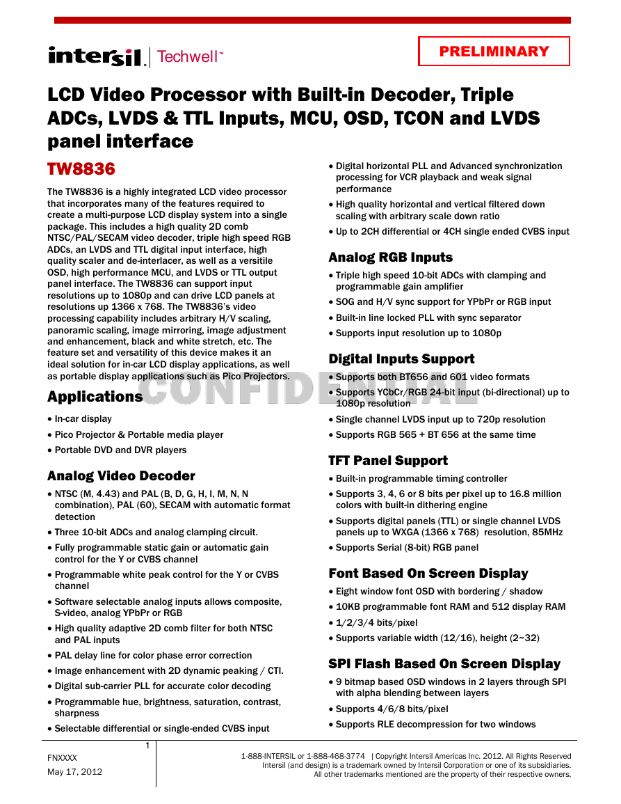

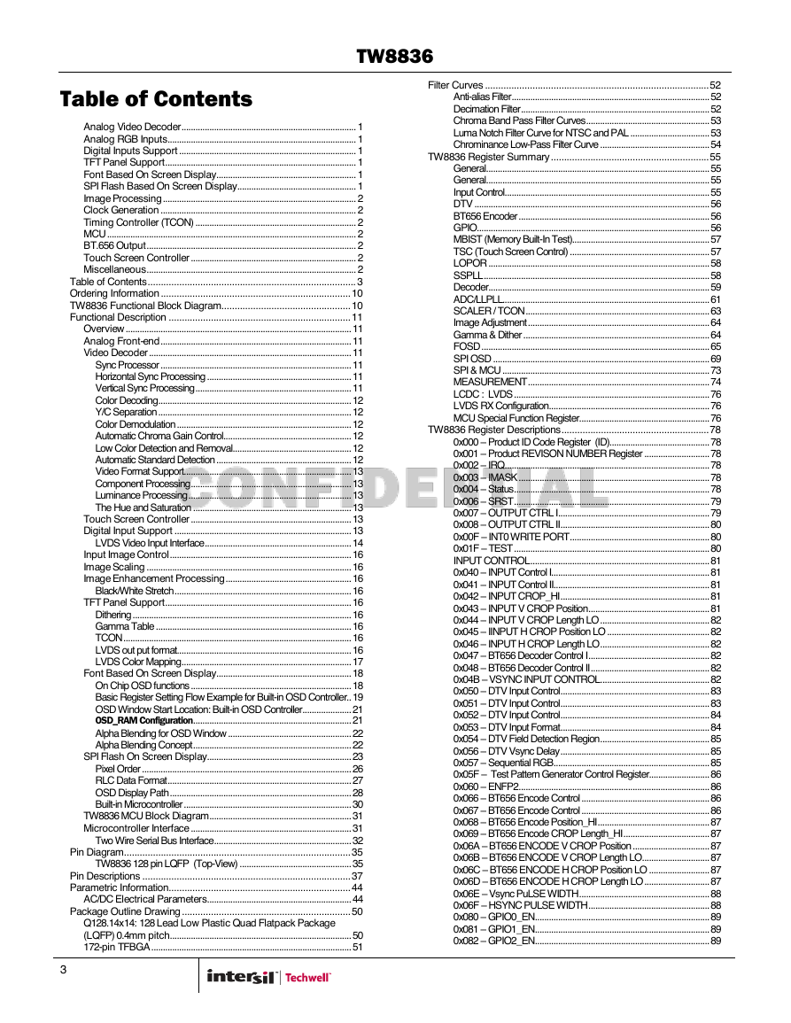
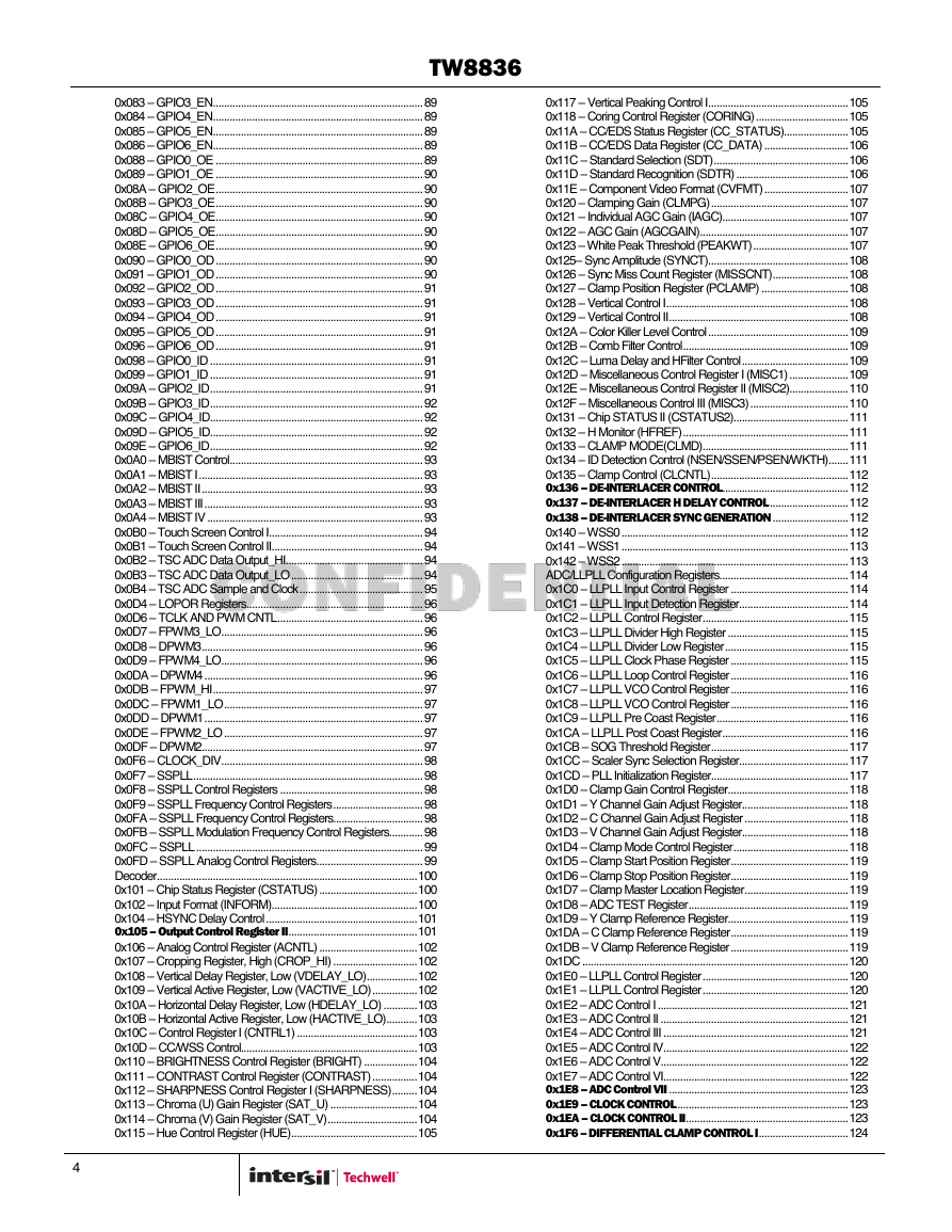
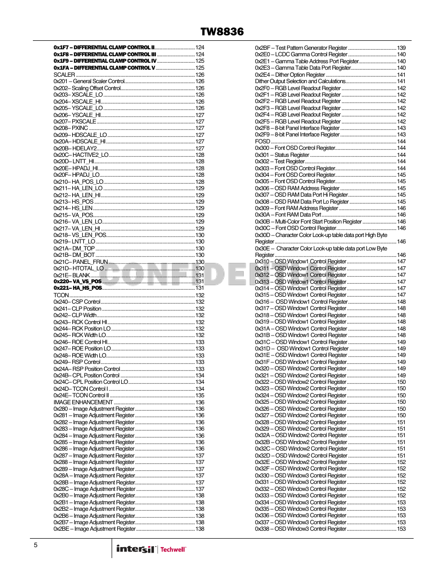
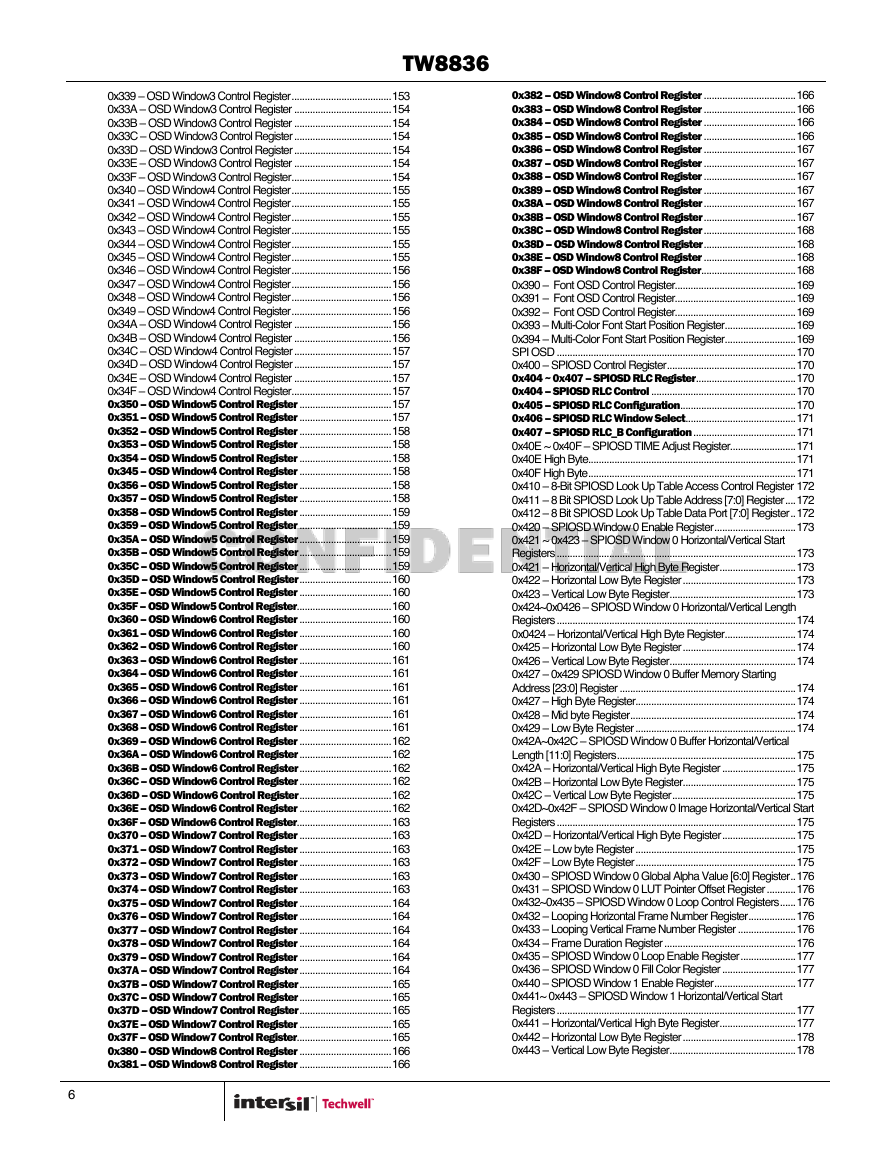
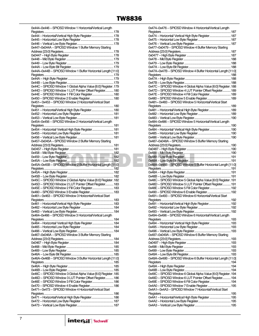
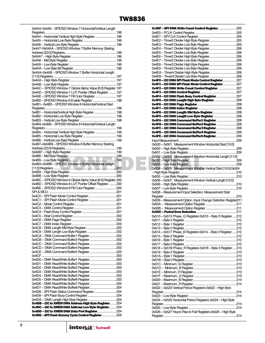


 2023年江西萍乡中考道德与法治真题及答案.doc
 2012年重庆南川中考生物真题及答案.doc
 2013年江西师范大学地理学综合及文艺理论基础考研真题.doc
 2020年四川甘孜小升初语文真题及答案I卷.doc
 2020年注册岩土工程师专业基础考试真题及答案.doc
 2023-2024学年福建省厦门市九年级上学期数学月考试题及答案.doc
 2021-2022学年辽宁省沈阳市大东区九年级上学期语文期末试题及答案.doc
 2022-2023学年北京东城区初三第一学期物理期末试卷及答案.doc
 2018上半年江西教师资格初中地理学科知识与教学能力真题及答案.doc
 2012年河北国家公务员申论考试真题及答案-省级.doc
 2020-2021学年江苏省扬州市江都区邵樊片九年级上学期数学第一次质量检测试题及答案.doc
 2022下半年黑龙江教师资格证中学综合素质真题及答案.doc