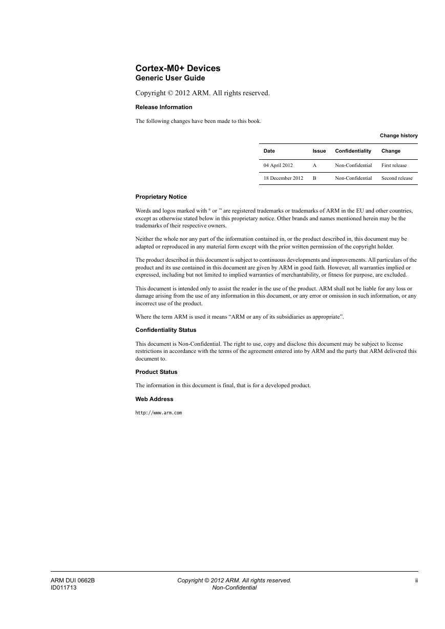
Cortex-M0+ Devices Generic User Guide
Contents
Preface
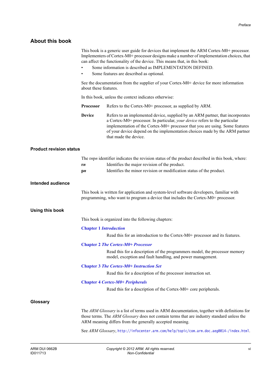
About this book
Product revision status
Intended audience
Using this book
Glossary
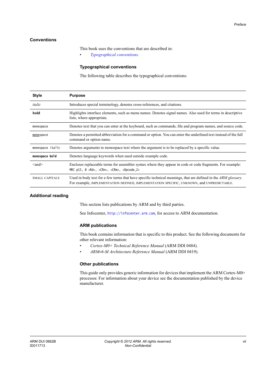
Conventions
Additional reading
Feedback
Feedback on this product
Feedback on content
1: Introduction
1.1 About the Cortex-M0+ processor and core peripherals
1.1.1 System-level interface
1.1.2 Optional integrated configurable debug
1.1.3 Cortex-M0+ processor features summary
1.1.4 Cortex-M0+ core peripherals
2: The Cortex-M0+ Processor
2.1 Programmers model
2.1.1 Processor modes and privilege levels for software execution
2.1.2 Stacks
2.1.3 Core registers
2.1.4 Exceptions and interrupts
2.1.5 Data types
2.1.6 The Cortex Microcontroller Software Interface Standard
2.2 Memory model
2.2.1 Memory regions, types and attributes
2.2.2 Memory system ordering of memory accesses
2.2.3 Behavior of memory accesses
2.2.4 Software ordering of memory accesses
2.2.5 Memory endianness
2.3 Exception model
2.3.1 Exception states
2.3.2 Exception types
2.3.3 Exception handlers
2.3.4 Vector table
2.3.5 Exception priorities
2.3.6 Exception entry and return
2.4 Fault handling
2.4.1 Lockup
2.5 Power management
2.5.1 Entering sleep mode
2.5.2 Wakeup from sleep mode
2.5.3 The optional Wakeup Interrupt Controller
2.5.4 The external event input
2.5.5 Power management programming hints
3: The Cortex-M0+ Instruction Set
3.1 Instruction set summary
3.2 Intrinsic functions
3.3 About the instruction descriptions
3.3.1 Operands
3.3.2 Restrictions when using PC or SP
3.3.3 Shift operations
3.3.4 Address alignment
3.3.5 PC-relative expressions
3.3.6 Conditional execution
3.4 Memory access instructions
3.4.1 ADR
3.4.2 LDR and STR, immediate offset
3.4.3 LDR and STR, register offset
3.4.4 LDR, PC-relative
3.4.5 LDM and STM
3.4.6 PUSH and POP
3.5 General data processing instructions
3.5.1 ADC, ADD, RSB, SBC, and SUB
3.5.2 AND, ORR, EOR, and BIC
3.5.3 ASR, LSL, LSR, and ROR
3.5.4 CMP and CMN
3.5.5 MOV and MVN
3.5.6 MULS
3.5.7 REV, REV16, and REVSH
3.5.8 SXT and UXT
3.5.9 TST
3.6 Branch and control instructions
3.6.1 B, BL, BX, and BLX
3.7 Miscellaneous instructions
3.7.1 BKPT
3.7.2 CPS
3.7.3 DMB
3.7.4 DSB
3.7.5 ISB
3.7.6 MRS
3.7.7 MSR
3.7.8 NOP
3.7.9 SEV
3.7.10 SVC
3.7.11 WFE
3.7.12 WFI
4: Cortex-M0+ Peripherals
4.1 About the Cortex-M0+ peripherals
4.2 Nested Vectored Interrupt Controller
4.2.1 Interrupt Set-Enable Register
4.2.2 Interrupt Clear-Enable Register
4.2.3 Interrupt Set-Pending Register
4.2.4 Interrupt Clear-Pending Register
4.2.5 Interrupt Priority Registers
4.2.6 Level-sensitive and pulse interrupts
4.2.7 NVIC usage hints and tips
4.3 System Control Block
4.3.1 CMSIS mapping of the Cortex-M0+ SCB registers
4.3.2 CPUID Register
4.3.3 Interrupt Control and State Register
4.3.4 Vector Table Offset Register
4.3.5 Application Interrupt and Reset Control Register
4.3.6 System Control Register
4.3.7 Configuration and Control Register
4.3.8 System Handler Priority Registers
4.3.9 SCB usage hints and tips
4.4 System timer, SysTick
4.4.1 SysTick Control and Status Register
4.4.2 SysTick Reload Value Register
4.4.3 SysTick Current Value Register
4.4.4 SysTick Calibration Value Register
4.4.5 SysTick usage hints and tips
4.5 Memory Protection Unit
4.5.1 MPU Type Register
4.5.2 MPU Control Register
4.5.3 MPU Region Number Register
4.5.4 MPU Region Base Address Register
4.5.5 MPU Region Attribute and Size Register
4.5.6 MPU access permission attributes
4.5.7 MPU access permission faults
4.5.8 Updating an MPU region
4.5.9 MPU usage hints and tips
4.6 Single-cycle I/O Port
A: Revisions




 2023年江西萍乡中考道德与法治真题及答案.doc
 2012年重庆南川中考生物真题及答案.doc
 2013年江西师范大学地理学综合及文艺理论基础考研真题.doc
 2020年四川甘孜小升初语文真题及答案I卷.doc
 2020年注册岩土工程师专业基础考试真题及答案.doc
 2023-2024学年福建省厦门市九年级上学期数学月考试题及答案.doc
 2021-2022学年辽宁省沈阳市大东区九年级上学期语文期末试题及答案.doc
 2022-2023学年北京东城区初三第一学期物理期末试卷及答案.doc
 2018上半年江西教师资格初中地理学科知识与教学能力真题及答案.doc
 2012年河北国家公务员申论考试真题及答案-省级.doc
 2020-2021学年江苏省扬州市江都区邵樊片九年级上学期数学第一次质量检测试题及答案.doc
 2022下半年黑龙江教师资格证中学综合素质真题及答案.doc