Foreword
1 Scope
2 References
3 Definitions and abbreviations
3.1 Definitions
3.2 Abbreviations
4 Architecture model and concepts
4.1 General concepts
4.2 Architecture reference model
4.2.1 Non-roaming architecture
4.2.2 Roaming architecture
4.2.3 Reference points
4.2.4 Warning System architecture
4.3 High level functions
4.3.1 General
4.3.2 Network access control functions
4.3.2.1 General
4.3.2.2 Network/Access network selection
4.3.2.3 Authentication and authorisation function
4.3.2.4 Admission control function
4.3.2.5 Policy and Charging Enforcement Function
4.3.2.6 Lawful Interception
4.3.3 Packet routeing and transfer functions
4.3.3.1 General
4.3.3.2 IP header compression function
4.3.3.3 Packet screening function
4.3.4 Security functions
4.3.4.1 Ciphering function
4.3.4.2 Integrity protection function
4.3.5 Mobility management functions
4.3.5.1 General
4.3.5.2 Reachability Management for UE in ECM-IDLE state
4.3.5.3 Tracking Area list management
4.3.5.4 Inter-eNodeB mobility anchor function
4.3.5.5 Inter-3GPP mobility anchor function
4.3.5.6 Idle mode signalling reduction function
4.3.5.7 Mobility Restrictions
4.3.6 Radio Resource Management functions
4.3.7 Network management functions
4.3.7.1 General
4.3.7.2 Load balancing between MMEs
4.3.7.3 Load re-balancing between MMEs
4.3.7.4 MME control of overload
4.3.8 Selection functions
4.3.8.1 PDN GW selection function (3GPP accesses)
4.3.8.2 Serving GW selection function
4.3.8.3 MME selection function
4.3.8.4 SGSN selection function
4.3.8.5 Selection of PCRF
4.3.9 IP network related functions
4.3.9.1 Domain Name Service function
4.3.9.2 DHCP function
4.3.10 Functionality for Connection of eNodeBs to Multiple MMEs
4.3.11 E-UTRAN Sharing Function
4.4 Network elements
4.4.1 E-UTRAN
4.4.2 MME
4.4.3 Gateway
4.4.3.1 General
4.4.3.2 Serving GW
4.4.3.3 PDN GW
4.4.4 SGSN
4.4.5 GERAN
4.4.6 UTRAN
4.4.7 PCRF
4.4.7.1 General
4.4.7.2 Home PCRF (H-PCRF)
4.4.7.3 Visited PCRF (V-PCRF)
4.4.8 PDN GW's associated AAA Server
4.5 Void
4.6 EPS Mobility Management and Connection Management states
4.6.1 General
4.6.2 Definition of main EPS Mobility Management states
4.6.2.1 EMM-DEREGISTERED
4.6.2.2 EMM-REGISTERED
4.6.3 Definition of EPS Connection Management states
4.6.3.1 ECM-IDLE
4.6.3.2 ECM-CONNECTED
4.6.4 State transition and functions
4.7 Overall QoS concept
4.7.1 PDN connectivity service
4.7.2 The EPS bearer
4.7.2.1 The EPS bearer in general
4.7.2.2 The EPS bearer with GTP-based S5/S8
4.7.2.3 The EPS bearer with PMIP-based S5/S8
4.7.3 Bearer level QoS parameters
4.7.4 Support for Application / Service Layer Rate Adaptation
4.7.5 Application of PCC in the Evolved Packet System
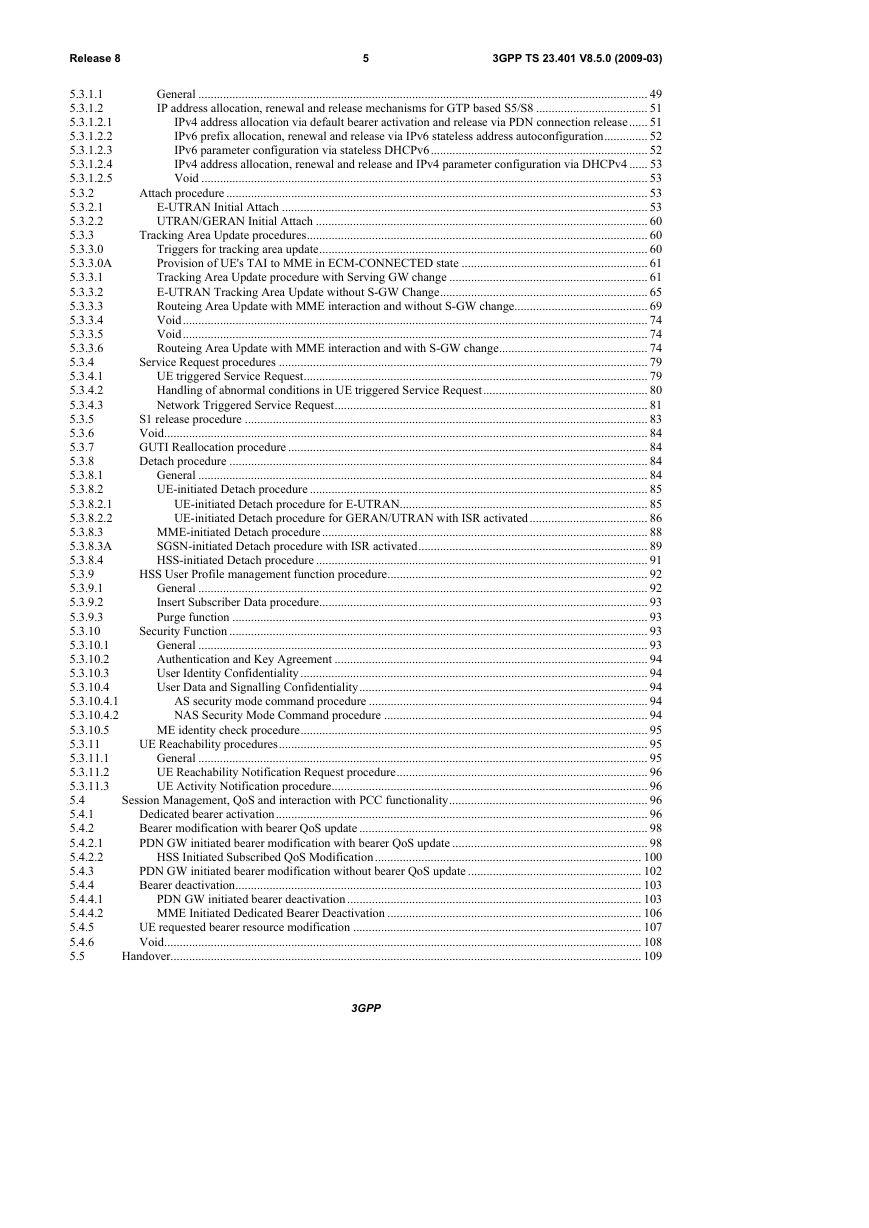
5 Functional description and information flows
5.1 Control and user planes
5.1.1 Control Plane
5.1.1.1 General
5.1.1.2 eNodeB - MME
5.1.1.3 UE - MME
5.1.1.4 SGSN - MME
5.1.1.5 SGSN - SGW
5.1.1.6 SGW - PGW
5.1.1.7 MME - MME
5.1.1.8 MME - SGW
5.1.1.9 MME - HSS
5.1.1.10 MME - EIR
5.1.1.11 CBC - eNodeB
5.1.2 User Plane
5.1.2.1 UE - PGW user plane with E-UTRAN
5.1.2.2 eNodeB - SGW
5.1.2.3 UE - PDN GW user plane with 2G access via the S4 interface
5.1.2.4 UE - PDN GW user plane with 3G access via the S12 interface
5.1.2.5 UE - PDN GW user plane with 3G access via the S4 interface
5.2 Identities
5.2.1 EPS bearer identity
5.2.2 Globally Unique Temporary UE Identity
5.2.3 Tracking Area Identity (TAI)
5.2.4 eNodeB S1-AP UE Identity (eNB S1-AP UE ID)
5.2.5 MME S1-AP UE Identity (MME S1-AP UE ID)
5.3 Authentication, security and location management
5.3.1 IP address allocation
5.3.1.1 General
5.3.1.2 IP address allocation, renewal and release mechanisms for GTP based S5/S8
5.3.1.2.1 IPv4 address allocation via default bearer activation and release via PDN connection release
5.3.1.2.2 IPv6 prefix allocation, renewal and release via IPv6 stateless address autoconfiguration
5.3.1.2.3 IPv6 parameter configuration via stateless DHCPv6
5.3.1.2.4 IPv4 address allocation, renewal and release and IPv4 parameter configuration via DHCPv4
5.3.1.2.5 Void
5.3.2 Attach procedure
5.3.2.1 E-UTRAN Initial Attach
5.3.2.2 UTRAN/GERAN Initial Attach
5.3.3 Tracking Area Update procedures
5.3.3.0 Triggers for tracking area update
5.3.3.0A Provision of UE's TAI to MME in ECM-CONNECTED state
5.3.3.1 Tracking Area Update procedure with Serving GW change
5.3.3.2 E-UTRAN Tracking Area Update without SGW Change
5.3.3.3 Routeing Area Update with MME interaction and without SGW change
5.3.3.4 Void
5.3.3.5 Void
5.3.3.6 Routeing Area Update with MME interaction and with SGW change
5.3.4 Service Request procedures
5.3.4.1 UE triggered Service Request
5.3.4.2 Handling of abnormal conditions in UE triggered Service Request
5.3.4.3 Network Triggered Service Request
5.3.5 S1 release procedure
5.3.6 Void
5.3.7 GUTI Reallocation procedure
5.3.8 Detach procedure
5.3.8.1 General
5.3.8.2 UE-initiated Detach procedure
5.3.8.2.1 UE-initiated Detach procedure for E-UTRAN
5.3.8.2.2 UE-initiated Detach procedure for GERAN/UTRAN with ISR activated
5.3.8.3 MME-initiated Detach procedure
5.3.8.3A SGSN-initiated Detach procedure with ISR activated
5.3.8.4 HSS-initiated Detach procedure
5.3.9 HSS User Profile management function procedure
5.3.9.1 General
5.3.9.2 Insert Subscriber Data procedure
5.3.9.3 Purge function
5.3.10 Security Function
5.3.10.1 General
5.3.10.2 Authentication and Key Agreement
5.3.10.3 User Identity Confidentiality
5.3.10.4 User Data and Signalling Confidentiality
5.3.10.4.1 AS security mode command procedure
5.3.10.4.2 NAS Security Mode Command procedure
5.3.10.5 ME identity check procedure
5.3.11 UE Reachability procedures
5.3.11.1 General
5.3.11.2 UE Reachability Notification Request procedure
5.3.11.3 UE Activity Notification procedure
5.4 Session Management, QoS and interaction with PCC functionality
5.4.1 Dedicated bearer activation
5.4.2 Bearer modification with bearer QoS update
5.4.2.1 PDN GW initiated bearer modification with bearer QoS update
5.4.2.2 HSS Initiated Subscribed QoS Modification
5.4.3 PDN GW initiated bearer modification without bearer QoS update
5.4.4 Bearer deactivation
5.4.4.1 PDN GW initiated bearer deactivation
5.4.4.2 MME Initiated Dedicated Bearer Deactivation
5.4.5 UE requested bearer resource modification
5.4.6 Void
5.5 Handover
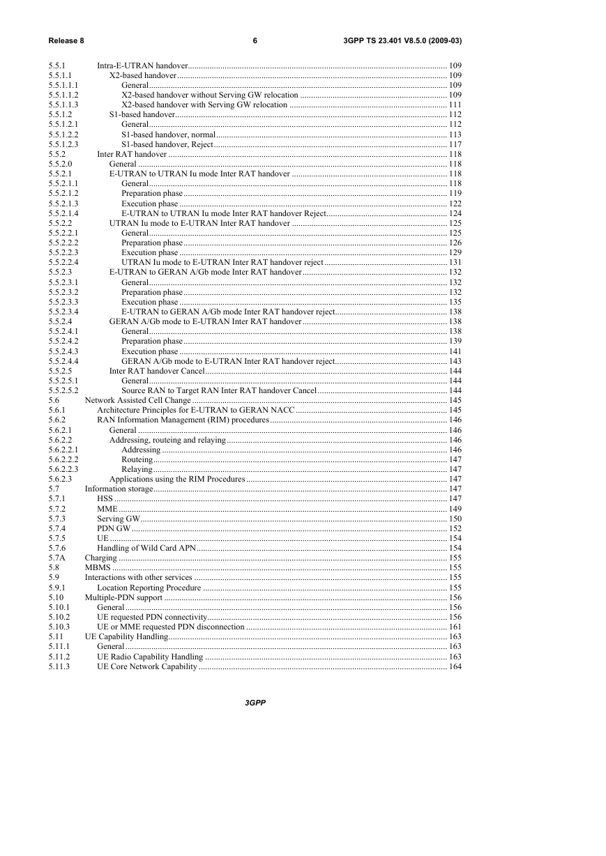
5.5.1 Intra-E-UTRAN handover
5.5.1.1 X2-based handover
5.5.1.1.1 General
5.5.1.1.2 X2-based handover without Serving GW relocation
5.5.1.1.3 X2-based handover with Serving GW relocation
5.5.1.2 S1-based handover
5.5.1.2.1 General
5.5.1.2.2 S1-based handover, normal
5.5.1.2.3 S1-based handover, Reject
5.5.2 Inter RAT handover
5.5.2.0 General
5.5.2.1 E-UTRAN to UTRAN Iu mode Inter RAT handover
5.5.2.1.1 General
5.5.2.1.2 Preparation phase
5.5.2.1.3 Execution phase
5.5.2.1.4 E-UTRAN to UTRAN Iu mode Inter RAT handover Reject
5.5.2.2 UTRAN Iu mode to E-UTRAN Inter RAT handover
5.5.2.2.1 General
5.5.2.2.2 Preparation phase
5.5.2.2.3 Execution phase
5.5.2.2.4 UTRAN Iu mode to E-UTRAN Inter RAT handover reject
5.5.2.3 E-UTRAN to GERAN A/Gb mode Inter RAT handover
5.5.2.3.1 General
5.5.2.3.2 Preparation phase
5.5.2.3.3 Execution phase
5.5.2.3.4 E-UTRAN to GERAN A/Gb mode Inter RAT handover reject
5.5.2.4 GERAN A/Gb mode to E-UTRAN Inter RAT handover
5.5.2.4.1 General
5.5.2.4.2 Preparation phase
5.5.2.4.3 Execution phase
5.5.2.4.4 GERAN A/Gb mode to E-UTRAN Inter RAT handover reject
5.5.2.5 Inter RAT handover Cancel
5.5.2.5.1 General
5.5.2.5.2 Source RAN to Target RAN Inter RAT handover Cancel
5.6 Network Assisted Cell Change
5.6.1 Architecture Principles for E-UTRAN to GERAN NACC
5.6.2 RAN Information Management (RIM) procedures
5.6.2.1 General
5.6.2.2 Addressing, routeing and relaying
5.6.2.2.1 Addressing
5.6.2.2.2 Routeing
5.6.2.2.3 Relaying
5.6.2.3 Applications using the RIM Procedures
5.7 Information storage
5.7.1 HSS
5.7.2 MME
5.7.3 Serving GW
5.7.4 PDN GW
5.7.5 UE
5.7.6 Handling of Wild Card APN
5.7A Charging
5.8 MBMS
5.9 Interactions with other services
5.9.1 Location Reporting Procedure
5.10 Multiple-PDN support
5.10.1 General
5.10.2 UE requested PDN connectivity
5.10.3 UE or MME requested PDN disconnection
5.11 UE Capability Handling
5.11.1 General
5.11.2 UE Radio Capability Handling
5.11.3 UE Core Network Capability
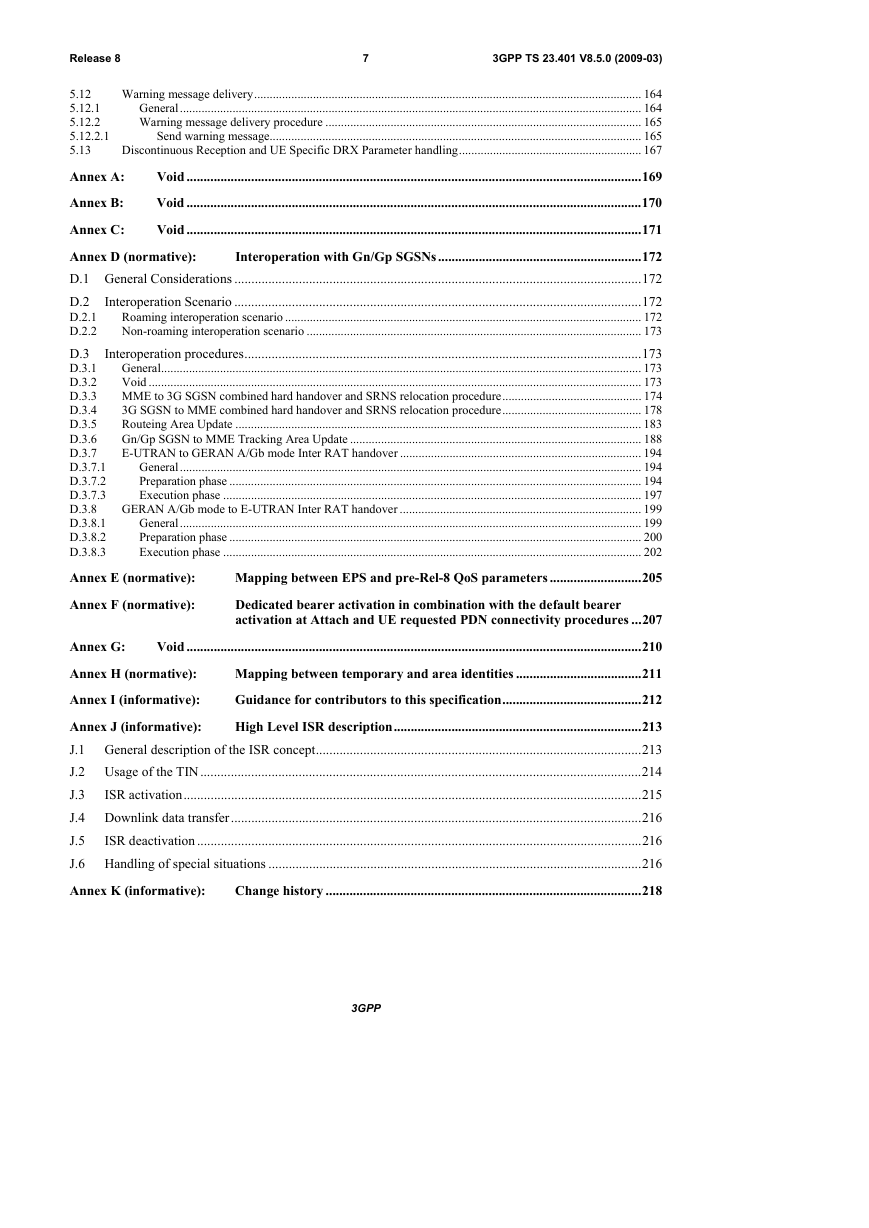
5.12 Warning message delivery
5.12.1 General
5.12.2 Warning message delivery procedure
5.12.2.1 Send warning message
5.13 Discontinuous Reception and UE Specific DRX Parameter handling
Annex A:Void
Annex B:Void
Annex C:Void
Annex D (normative):Interoperation with Gn/Gp SGSNs
D.1 General Considerations
D.2 Interoperation Scenario
D.2.1 Roaming interoperation scenario
D.2.2 Non-roaming interoperation scenario
D.3 Interoperation procedures
D.3.1 General
D.3.2 Void
D.3.3 MME to 3G SGSN combined hard handover and SRNS relocation procedure
D.3.4 3G SGSN to MME combined hard handover and SRNS relocation procedure
D.3.5 Routeing Area Update
D.3.6 Gn/Gp SGSN to MME Tracking Area Update
D.3.7 E-UTRAN to GERAN A/Gb mode Inter RAT handover
D.3.7.1 General
D.3.7.2 Preparation phase
D.3.7.3 Execution phase
D.3.8 GERAN A/Gb mode to E-UTRAN Inter RAT handover
D.3.8.1 General
D.3.8.2 Preparation phase
D.3.8.3 Execution phase
Annex E (normative):Mapping between EPS and pre-Rel-8 QoS parameters
Annex F (normative):Dedicated bearer activation in combination with the default bearer activation at Attach and UE requested PDN connectivity procedures
Annex G:Void
Annex H (normative):Mapping between temporary and area identities
Annex I (informative):Guidance for contributors to this specification
Annex J (informative):High Level ISR description
J.1 General description of the ISR concept
J.2 Usage of the TIN
J.3 ISR activation
J.4 Downlink data transfer
J.5 ISR deactivation
J.6 Handling of special situations
Annex K (informative):Change history


 2023年江西萍乡中考道德与法治真题及答案.doc
 2012年重庆南川中考生物真题及答案.doc
 2013年江西师范大学地理学综合及文艺理论基础考研真题.doc
 2020年四川甘孜小升初语文真题及答案I卷.doc
 2020年注册岩土工程师专业基础考试真题及答案.doc
 2023-2024学年福建省厦门市九年级上学期数学月考试题及答案.doc
 2021-2022学年辽宁省沈阳市大东区九年级上学期语文期末试题及答案.doc
 2022-2023学年北京东城区初三第一学期物理期末试卷及答案.doc
 2018上半年江西教师资格初中地理学科知识与教学能力真题及答案.doc
 2012年河北国家公务员申论考试真题及答案-省级.doc
 2020-2021学年江苏省扬州市江都区邵樊片九年级上学期数学第一次质量检测试题及答案.doc
 2022下半年黑龙江教师资格证中学综合素质真题及答案.doc