logo资料库

瑞萨MCU的汇编指令手册.pdf

第1页 / 共306页
第2页 / 共306页
第3页 / 共306页
第4页 / 共306页
第5页 / 共306页
第6页 / 共306页
第7页 / 共306页
第8页 / 共306页
资料共306页,剩余部分请下载后查看
Keep safety first in your circuit designs!
Notes regarding these materials
Using This Manual
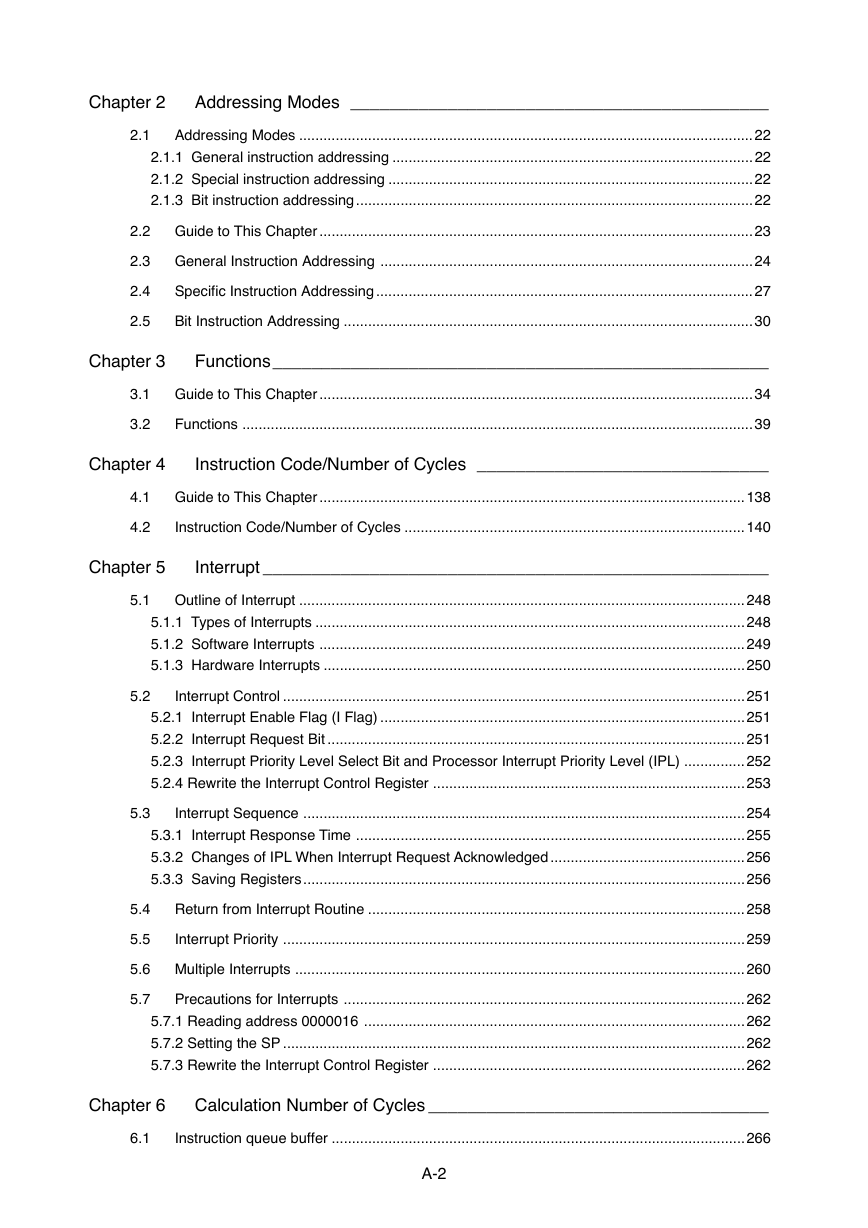
Table of Contents
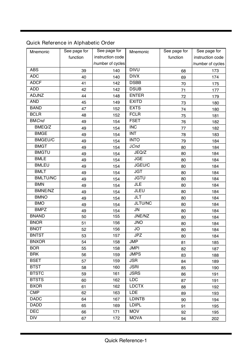
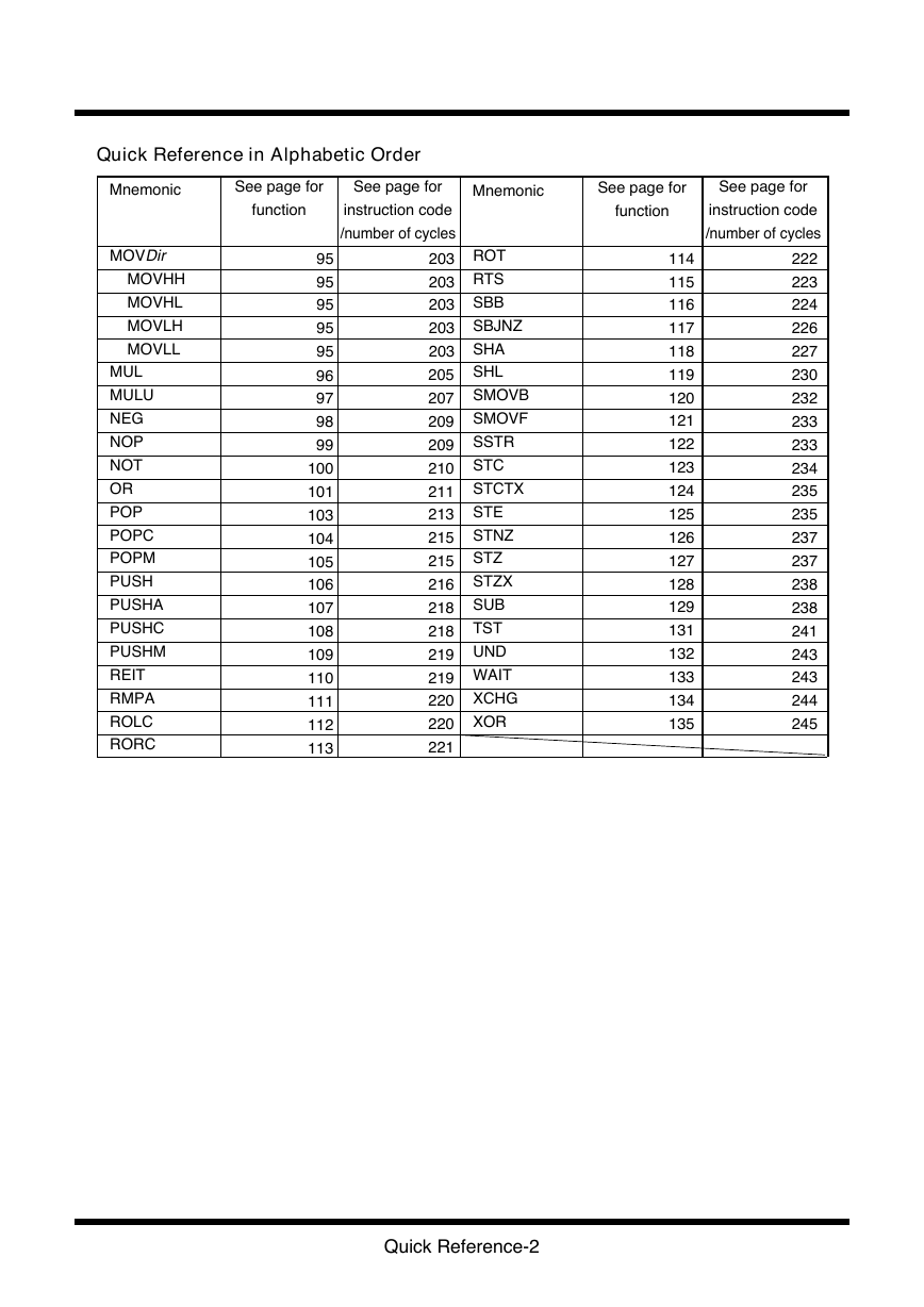
Quick Reference in Alphabetic Order
Quick Reference by Function
Quick Reference by Addressing (general instruction addressing)
Quick Reference by Addressing (special instruction addressing)
Quick Reference by Addressing (bit instruction addressing)
Chapter 1 Overview
1.1 Features of M16C/60,M16C/20,M16C/Tiny series
1.1.1 Features of M16C/60,M16C/20,M16C/Tiny series
1.1.2 Speed performance
1.2 Address Space
1.3 Register Configuration
1.3.1 Data registers (R0, R0H, R0L, R1, R1H, R1L, R2, and R3)
1.3.2 Address registers (A0 and A1)
1.3.3 Frame base register (FB)
1.3.4 Program counter (PC)
1.3.5 Interrupt table register (INTB)
1.3.6 User stack pointer (USP) and interrupt stack pointer (ISP)
1.3.7 Static base register (SB)
1.3.8 Flag register (FLG)
1.4 Flag Register (FLG)
1.4.1 Bit 0: Carry flag (C flag)
1.4.2 Bit 1: Debug flag (D flag)
1.4.3 Bit 2: Zero flag (Z flag)
1.4.4 Bit 3: Sign flag (S flag)
1.4.5 Bit 4: Register bank select flag (B flag)
1.4.6 Bit 5: Overflow flag (O flag)
1.4.7 Bit 6: Interrupt enable flag (I flag)
1.4.8 Bit 7: Stack pointer select flag (U flag)
1.4.9 Bits 8-11: Reserved area
1.4.10 Bits 12-14: Processor interrupt priority level (IPL)
1.4.11 Bit 15: Reserved area
1.5 Register Bank
1.6 Internal State after Reset is Cleared
1.7 Data Types
1.7.1 Integer
1.7.2 Decimal
1.7.3 Bits
1.7.4 String
1.8 Data Arrangement
1.8.1 Data Arrangement in Register
1.8.2 Data Arrangement in Memory
1.9 Instruction Format
1.9.1 Generic format (:G)
1.9.2 Quick format (:Q)
1.9.3 Short format (:S)
1.9.4 Zero format (:Z)
1.10 Vector Table
1.10.1 Fixed Vector Table
1.10.2 Variable Vector Table
Chapter 2 Addressing Modes
2.1 Addressing Modes
2.1.1 General instruction addressing
2.1.2 Special instruction addressing
2.1.3 Bit instruction addressing
2.2 Guide to This Chapter
2.3 General Instruction Addressing
2.4 Special Instruction Addressing
2.5 Bit Instruction Addressing
Chapter 3 Functions
3.1 Guide to This Chapter
3.2 Functions
Chapter 4 Instruction Code/Number of Cycles
4.1 Guide to This Chapter
4.2 Instruction Code/Number of Cycles
Chapter 5 Interrupt
5.1 Outline of Interrupt
5.1.1 Types of Interrupts
5.1.2 Software Interrupts
5.1.3 Hardware Interrupts
5.2 Interrupt Control
5.2.1 Interrupt Enable Flag (I Flag)
5.2.2 Interrupt Request Bit
5.2.3 Interrupt Priority Level Select Bit and Processor Interrupt Priority Level (IPL)
5.2.4 Rewrite the Interrupt Control Register
5.3 Interrupt Sequence
5.3.1 Interrupt Response Time
5.3.2 Changes of IPL When Interrupt Request Acknowledged
5.3.3 Saving Registers
5.4 Return from Interrupt Routine
5.5 Interrupt Priority
5.6 Multiple Interrupts
5.7 Precautions for Interrupts
5.7.1 Reading address 0000016
5.7.2 Setting the SP
5.7.3 Rewrite the Interrupt Control Register
Chapter 6 Calculation Number of Cycles
6.1 Instruction queue buffer
Q & A
Glossary
Table of symbols
Index
REVISION HISTORY
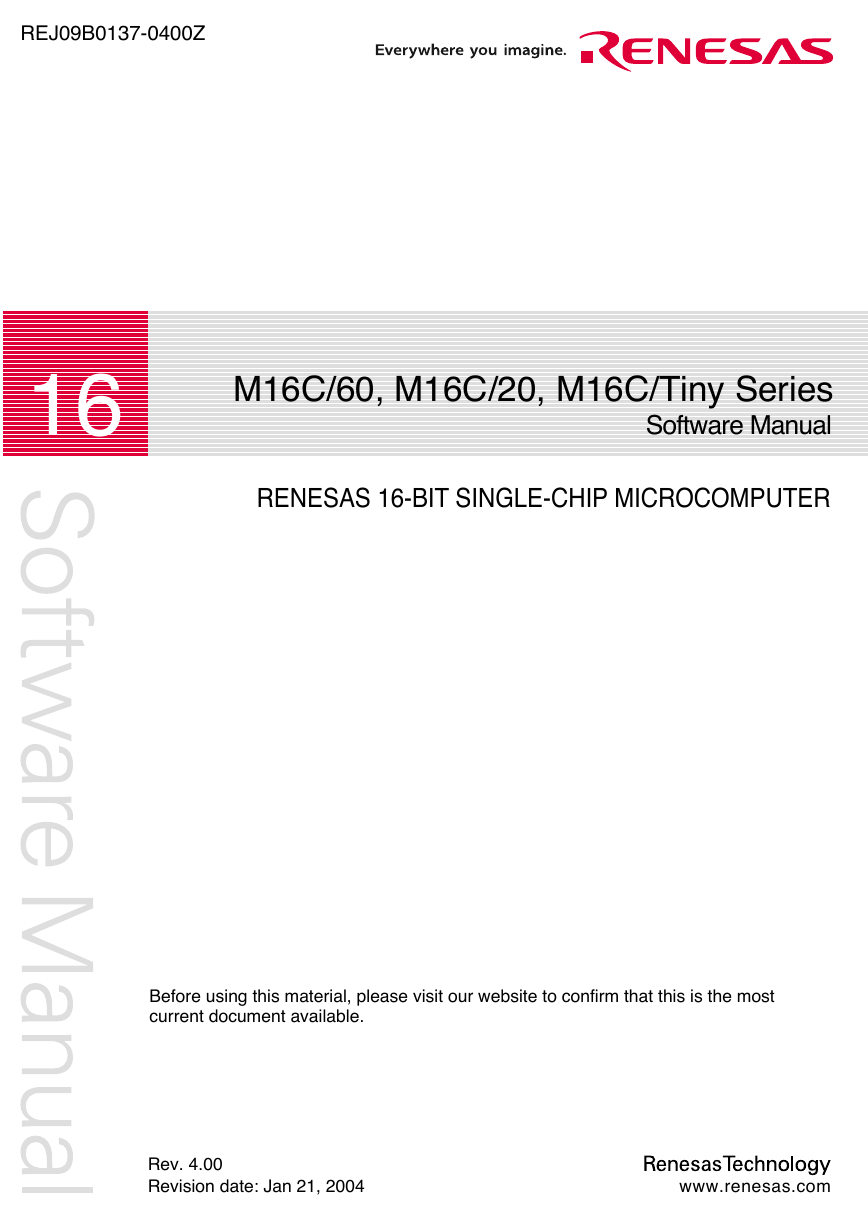
REJ09B0137-0400Z 16 M16C/60, M16C/20, M16C/Tiny Series Software Manual RENESAS 16-BIT SINGLE-CHIP MICROCOMPUTER Before using this material, please visit our website to confirm that this is the most current document available. Rev. 4.00 Revision date: Jan 21, 2004 www.renesas.com
Keep safety first in your circuit designs! 1. Renesas Technology Corporation puts the maximum effort into making semiconductor prod- ucts better and more reliable, but there is always the possibility that trouble may occur with them. Trouble with semiconductors may lead to personal injury, fire or property damage. Remember to give due consideration to safety when making your circuit designs, with ap- propriate measures such as (i) placement of substitutive, auxiliary circuits, (ii) use of non- flammable material or (iii) prevention against any malfunction or mishap. Notes regarding these materials 1. These materials are intended as a reference to assist our customers in the selection of the Renesas Technology Corporation product best suited to the customer's application; they do not convey any license under any intellectual property rights, or any other rights, belonging to Renesas Technology Corporation or a third party. 2. Renesas Technology Corporation assumes no responsibility for any damage, or infringe- ment of any third-party's rights, originating in the use of any product data, diagrams, charts, programs, algorithms, or circuit application examples contained in these materials. 3. All information contained in these materials, including product data, diagrams, charts, pro- grams and algorithms represents information on products at the time of publication of these materials, and are subject to change by Renesas Technology Corporation without notice due to product improvements or other reasons. It is therefore recommended that custom- ers contact Renesas Technology Corporation or an authorized Renesas Technology Cor- poration product distributor for the latest product information before purchasing a product listed herein. The information described here may contain technical inaccuracies or typographical errors. Renesas Technology Corporation assumes no responsibility for any damage, liability, or other loss rising from these inaccuracies or errors. Please also pay attention to information published by Renesas Technology Corporation by various means, including the Renesas Technology Corporation Semiconductor home page (http://www.renesas.com). 4. When using any or all of the information contained in these materials, including product data, diagrams, charts, programs, and algorithms, please be sure to evaluate all informa- tion as a total system before making a final decision on the applicability of the information and products. Renesas Technology Corporation assumes no responsibility for any dam- age, liability or other loss resulting from the information contained herein. 5. Renesas Technology Corporation semiconductors are not designed or manufactured for use in a device or system that is used under circumstances in which human life is poten- tially at stake. Please contact Renesas Technology Corporation or an authorized Renesas Technology Corporation product distributor when considering the use of a product con- tained herein for any specific purposes, such as apparatus or systems for transportation, vehicular, medical, aerospace, nuclear, or undersea repeater use. 6. The prior written approval of Renesas Technology Corporation is necessary to reprint or reproduce in whole or in part these materials. 7. If these products or technologies are subject to the Japanese export control restrictions, they must be exported under a license from the Japanese government and cannot be im- ported into a country other than the approved destination. Any diversion or reexport contrary to the export control laws and regulations of Japan and/ or the country of destination is prohibited. 8. Please contact Renesas Technology Corporation for further details on these materials or the products contained therein.
Using This Manual This manual is written for the M16C/60, M16C/20, M16C/Tiny series software. This manual can be used for all types of microcomputers having the M16C/60 series CPU core. The reader of this manual is expected to have the basic knowledge of electric and logic circuits and microcomputers. This manual consists of five chapters. The following lists the chapters and sections to be referred to when you want to know details on some specific subject. • To understand the outline of the M16C/60, M16C/20, M16C/Tiny series and its features ................................................................................................................Chapter 1, “Overview” • To understand the operation of each addressing mode .................. Chapter 2, “Addressing Modes” • To understand instruction functions (Syntax, operation, function, selectable src/dest (label), flag changes, description example, related instructions).............................................................................. Chapter 3, “Functions” • To understand instruction code and cycles ......... Chapter 4, “Instruction Code/Number of Cycles” This manual also contains quick references immediately after the Table of Contents. These quick references will help you quickly find the pages for the functions or instruction code/ number of cycles you want to know. • To find pages from mnemonic .................................. Quick Reference in Alphabetic Order • To find pages from function and mnemonic ......................... Quick Reference by Function • To find pages from mnemonic and addressing ................ Quick Reference by Addressing A table of symbols, a glossary, and an index are appended at the end of this manual.
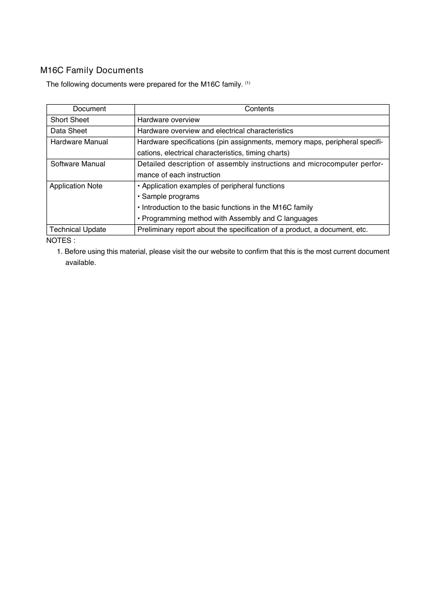
M16C Family Documents The following documents were prepared for the M16C family. (1) Document Short Sheet Data Sheet Hardware Manual Software Manual Application Note Technical Update NOTES : Contents Hardware overview Hardware overview and electrical characteristics Hardware specifications (pin assignments, memory maps, peripheral specifi- cations, electrical characteristics, timing charts) Detailed description of assembly instructions and microcomputer perfor- mance of each instruction • Application examples of peripheral functions • Sample programs • Introduction to the basic functions in the M16C family • Programming method with Assembly and C languages Preliminary report about the specification of a product, a document, etc. 1. Before using this material, please visit the our website to confirm that this is the most current document available.
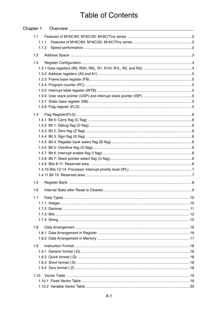
Table of Contents Chapter 1 Overview ___________________________________________________ 1.1 Features of M16C/60, M16C/20, M16C/Tiny series ............................................................... 2 1.1.1 Features of M16C/60, M16C/20, M16C/Tiny series ......................................................... 2 1.1.2 Speed performance ..........................................................................................................2 1.2 Address Space ....................................................................................................................... 3 1.3 Register Configuration ............................................................................................................ 4 1.3.1 Data registers (R0, R0H, R0L, R1, R1H, R1L, R2, and R3) ................................................4 1.3.2 Address registers (A0 and A1) ............................................................................................ 5 1.3.3 Frame base register (FB).................................................................................................... 5 1.3.4 Program counter (PC)......................................................................................................... 5 1.3.5 Interrupt table register (INTB) ............................................................................................. 5 1.3.6 User stack pointer (USP) and interrupt stack pointer (ISP) ................................................5 1.3.7 Static base register (SB) ..................................................................................................... 5 1.3.8 Flag register (FLG) ............................................................................................................. 5 1.4 Flag Register(FLG) .................................................................................................................6 1.4.1 Bit 0: Carry flag (C flag) ...................................................................................................... 6 1.4.2 Bit 1: Debug flag (D flag) .................................................................................................... 6 1.4.3 Bit 2: Zero flag (Z flag) ........................................................................................................ 6 1.4.4 Bit 3: Sign flag (S flag) ........................................................................................................ 6 1.4.5 Bit 4: Register bank select flag (B flag)...............................................................................6 1.4.6 Bit 5: Overflow flag (O flag)................................................................................................. 6 1.4.7 Bit 6: Interrupt enable flag (I flag) .......................................................................................6 1.4.8 Bit 7: Stack pointer select flag (U flag)................................................................................6 1.4.9 Bits 8-11: Reserved area .................................................................................................... 6 1.4.10 Bits 12-14: Processor interrupt priority level (IPL) ............................................................. 7 1.4.11 Bit 15: Reserved area ........................................................................................................ 7 1.5 Register Bank ......................................................................................................................... 8 1.6 Internal State after Reset is Cleared .......................................................................................9 1.7 Data Types ........................................................................................................................... 10 1.7.1 Integer............................................................................................................................... 10 1.7.2 Decimal ............................................................................................................................. 11 1.7.3 Bits .................................................................................................................................... 12 1.7.4 String ................................................................................................................................ 15 1.8 Data Arrangement ................................................................................................................ 16 1.8.1 Data Arrangement in Register .......................................................................................... 16 1.8.2 Data Arrangement in Memory ........................................................................................... 17 1.9 Instruction Format ................................................................................................................. 18 1.9.1 Generic format (:G) ........................................................................................................... 18 1.9.2 Quick format (:Q) .............................................................................................................. 18 1.9.3 Short format (:S) ............................................................................................................... 18 1.9.4 Zero format (:Z)................................................................................................................. 18 1.10 Vector Table ......................................................................................................................... 19 1.10.1 Fixed Vector Table .......................................................................................................... 19 1.10.2 Variable Vector Table ...................................................................................................... 20 A-1
Chapter 2 Addressing Modes ___________________________________________ 2.1 Addressing Modes ................................................................................................................22 2.1.1 General instruction addressing .........................................................................................22 2.1.2 Special instruction addressing ..........................................................................................22 2.1.3 Bit instruction addressing ..................................................................................................22 2.2 Guide to This Chapter ...........................................................................................................23 2.3 General Instruction Addressing ............................................................................................24 2.4 Specific Instruction Addressing ............................................................................................. 27 2.5 Bit Instruction Addressing .....................................................................................................30 Chapter 3 Functions___________________________________________________ 3.1 Guide to This Chapter ...........................................................................................................34 3.2 Functions ..............................................................................................................................39 Chapter 4 Instruction Code/Number of Cycles ______________________________ 4.1 Guide to This Chapter .........................................................................................................138 4.2 Instruction Code/Number of Cycles ....................................................................................140 Chapter 5 Interrupt ____________________________________________________ 5.1 Outline of Interrupt ..............................................................................................................248 5.1.1 Types of Interrupts ..........................................................................................................248 5.1.2 Software Interrupts .........................................................................................................249 5.1.3 Hardware Interrupts ........................................................................................................250 5.2 Interrupt Control ..................................................................................................................251 5.2.1 Interrupt Enable Flag (I Flag) ..........................................................................................251 5.2.2 Interrupt Request Bit .......................................................................................................251 5.2.3 Interrupt Priority Level Select Bit and Processor Interrupt Priority Level (IPL) ...............252 5.2.4 Rewrite the Interrupt Control Register .............................................................................253 5.3 Interrupt Sequence .............................................................................................................254 5.3.1 Interrupt Response Time ................................................................................................255 5.3.2 Changes of IPL When Interrupt Request Acknowledged ................................................256 5.3.3 Saving Registers.............................................................................................................256 5.4 Return from Interrupt Routine .............................................................................................258 5.5 Interrupt Priority ..................................................................................................................259 5.6 Multiple Interrupts ...............................................................................................................260 5.7 Precautions for Interrupts ...................................................................................................262 5.7.1 Reading address 0000016 ..............................................................................................262 5.7.2 Setting the SP ..................................................................................................................262 5.7.3 Rewrite the Interrupt Control Register .............................................................................262 Chapter 6 Calculation Number of Cycles ___________________________________ 6.1 Instruction queue buffer ......................................................................................................266 A-2
Quick Reference in Alphabetic Order Mnemonic See page for See page for Mnemonic See page for See page for function instruction code /number of cycles function instruction code /number of cycles ABS ADC ADCF ADD ADJNZ AND BAND BCLR BMCnd BMEQ/Z BMGE BMGEU/C BMGT BMGTU BMLE BMLEU BMLT BMLTU/NC BMN BMNE/NZ BMNO BMO BMPZ BNAND BNOR BNOT BNTST BNXOR BOR BRK BSET BTST BTSTC BTSTS BXOR CMP DADC DADD DEC DIV 39 40 41 42 44 45 47 48 49 49 49 49 49 49 49 49 49 49 49 49 49 49 49 50 51 52 53 54 55 56 57 58 59 60 61 62 64 65 66 67 140 140 142 142 148 149 152 152 154 154 154 154 154 154 154 154 154 154 154 154 154 154 154 155 156 156 157 158 158 159 159 160 161 162 162 163 167 169 171 172 DIVU DIVX DSBB DSUB ENTER EXITD EXTS FCLR FSET INC INT INTO JCnd JEQ/Z JGE JGEU/C JGT JGTU JLE JLEU JLT JLTU/NC JN JNE/NZ JNO JO JPZ JMP JMPI JMPS JSR JSRI JSRS LDC LDCTX LDE LDINTB LDIPL MOV MOVA Quick Reference-1 68 69 70 71 72 73 74 75 76 77 78 79 80 80 80 80 80 80 80 80 80 80 80 80 80 80 80 81 82 83 84 85 86 87 88 89 90 91 92 94 173 174 175 177 179 180 180 181 182 182 183 184 184 184 184 184 184 184 184 184 184 184 184 184 184 184 184 185 187 188 189 190 191 191 192 193 194 195 195 202
Quick Reference in Alphabetic Order Mnemonic See page for See page for Mnemonic See page for See page for MOVDir MOVHH MOVHL MOVLH MOVLL MUL MULU NEG NOP NOT OR POP POPC POPM PUSH PUSHA PUSHC PUSHM REIT RMPA ROLC RORC function instruction code /number of cycles 203 203 203 203 203 205 207 209 209 210 211 213 215 215 216 218 218 219 219 220 220 221 95 95 95 95 95 96 97 98 99 100 101 103 104 105 106 107 108 109 110 111 112 113 ROT RTS SBB SBJNZ SHA SHL SMOVB SMOVF SSTR STC STCTX STE STNZ STZ STZX SUB TST UND WAIT XCHG XOR function 114 115 116 117 118 119 120 121 122 123 124 125 126 127 128 129 131 132 133 134 135 instruction code /number of cycles 222 223 224 226 227 230 232 233 233 234 235 235 237 237 238 238 241 243 243 244 245 Quick Reference-2
分享到:
收藏