FM2018-380 Datasheet
FM2018-380
Datasheet v1.0
October 2008
DS v1.0, 24Oct08
1
�
FM2018-380 Datasheet
THIS DOCUMENT CONTAINS INFORMATION ON A PREPRODUCTION PRODUCT. SPECIFICATIONS AND PREPRODUCTION
INFORMATION HEREIN ARE SUBJECT TO CHANGE WITHOUT NOTICE.
FORTÉMEDIA, INC. PRODUCTS ARE INTENDED FOR NEITHER LIFE SAVING NOR LIFE SUSTAINING APPLICATIONS AND
FORTÉMEDIA, INC. THUS, ASSUMES NO LIABILITY IN SUCH USAGES. FORTÉMEDIA, INC. PRDUCTS MAY ONLY BE USED IN
LIFE-SUPPORT DEVICES OR SYSTEMS WITH THE EXPRESS WRITTEN APPROVAL OF FORTÉMEDIA, INC., IF A FAILURE OF
SUCH COMPONENTS CAN REASONABLY BE EXPECTED TO CAUSE THE FAILURE OF THAT LIFE-SUPPORT DEVICE OR SYSTEM,
OR TO AFFECT THE SAFETY OR EFFECTIVENESS OF THAT DEVICE OR SYSTEM. LIFE SUPPORT DEVICES OR SYSTEMS ARE
INTENDED TO BE IMPLANTED IN THE HUMAN BODY, OR TO SUPPORT AND/OR MAINTAIN AND SUSTAIN AND/OR PROTECT
HUMAN LIFE. IF THEY FAIL, IT IS REASONABLE TO ASSUME THAT THE HEALTH OF THE USER OR OTHER PERSONS MAY BE
ENDANGERED.
WE HEREIN DISCLAIM ANY AND ALL WARRANTIES, INCLUDING BUT NOT LIMITED TO WARRANTIES OF NON-INFRINGEMENT,
REGARDING CIRCUITS, DESCRIPTIONS AND CHARTS STATED HEREIN.
Fortémedia, SAM, Fortémedia and SAM logos are trademarks of Fortémedia,, Inc.
All other trademarks belong to their respective companies.
Copyright © 2006-2008 Fortémedia all rights reserved.
DS v1.0, 24Oct08
2
�
FM2018-380 Datasheet
CONTENTS
1.
2.
5.1.
1.1.
1.2.
1.3.
1.4.
1.5.
1.6.
INTRODUCTION.......................................................................................................................................6
OVERVIEW ...........................................................................................................................................6
HARDWARE FEATURES.........................................................................................................................7
22-PIN CSP PACKAGE PIN CONFIGURATION.........................................................................................8
48-PIN QFN PACKAGE PIN CONFIGURATION........................................................................................8
INTERNAL HARDWARE BLOCK DIAGRAM ............................................................................................9
SYSTEM BLOCK DIAGRAM WITH FM2018-380.....................................................................................9
FUNCTIONAL DESCRIPTION .............................................................................................................10
SHI (SERIAL HOST INTERFACE) MODE...............................................................................................10
2.1.
EEPROM MODE................................................................................................................................12
2.2.
ADC (ANALOG TO DIGITAL CONVERTERS AND ANALOG INPUTS) .....................................................13
2.3.
DAC (DIGITAL TO ANALOG CONVERTER) AND ANALOG OUTPUT .....................................................14
2.4.
POWER SUPPLY ..................................................................................................................................14
2.5.
CLOCK SOURCE..................................................................................................................................14
2.6.
RESET AND WARM RESET ..................................................................................................................15
2.7.
2.8.
POWER DOWN MODE .........................................................................................................................15
ANALOG COMMUNICATION MODE......................................................................................................16
2.9.
2.10. NORMAL OPERATION MODE WITH 1 OR 2 MICROPHONES, AND WITH OR WITHOUT BEAM-FORMING
FUNCTION. ........................................................................................................................................................16
ELECTRICAL AND TIMING SPECIFICATION................................................................................17
POWER, DC, AND AC CHARACTERISTICS...........................................................................................17
TIMING CHARACTERISTICS.................................................................................................................19
VOICE PROCESSOR DSP PERFORMANCE DETAILS ..............................................................................21
OPERATIONAL STATE TRANSITION DIAGRAM ....................................................................................22
PIN DEFINITION.....................................................................................................................................23
PACKAGE.................................................................................................................................................25
PACKAGE DIMENSION – 22-PIN CSP PACKAGE...................................................................................25
6. ORDERING AND STORING INFORMATION ...................................................................................28
7. AUDIO MEASUREMENT SYSTEM .....................................................................................................29
AEC MEASUREMENT CONDITION ......................................................................................................29
STATIONARY NOISE SUPPRESSION CONDITION ..................................................................................29
8. REFERENCES AUDIO MEASUREMENT SYSTEM .........................................................................30
TERMINOLOGY ...................................................................................................................................30
RELATED DOCUMENTS.......................................................................................................................30
3.1.
3.2.
3.3.
3.4.
7.1.
7.2.
8.1.
8.2.
3.
4.
5.
DS v1.0, 24Oct08
3
�
FM2018-380 Datasheet
FIGURES
Figure 1: 22-pin CSP Pin Configuration..........................................................................................8
Figure 2: 48-pin QFN Pin Configuration.........................................................................................8
Figure 3: FM2018-380 Hardware Block Diagram ............................................................................9
Figure 4: System Application Block Diagram ..................................................................................9
Figure 5: SHI Command Protocol with Start(S), Restart(Sr) and Stop(P) ........................................10
Figure 6: SHI Command sequence with “Sync” word and command entry byte...............................11
Figure 7: Command and parameter raw files stored in EEPROM ....................................................12
Figure 8: Analog Input Block Diagram.........................................................................................13
Figure 9: Analog Output Block Diagram ......................................................................................14
Figure 10: Crystal with Internal Clock Generator and External Clock Source reference circuit ...........15
Figure 11: Cold Reset Timing Chart ............................................................................................20
Figure 12: External Hardware Power Reset Timing Chart ..............................................................20
Figure 13: External Power-Down Timing Chart.............................................................................21
Figure 14: Operation State Transition Diagram ............................................................................22
Figure 15: CSP Package Dimensions ...........................................................................................25
Figure 16: QFN Package Dimensions...........................................................................................27
Figure 17: Echo Cancellation Test Setup .....................................................................................29
Figure 18: Noise Suppression Test Setup ....................................................................................29
TABLES
Table 1: SHI /EEPROM Command Entry Name.............................................................................11
Table 2: SHI /EEPROM Serial Command Entry Byte Descriptions (1)..............................................11
Table 3: SHI /EEPROM Serial Command Entry Byte Descriptions (2)..............................................11
Table 4: Electric Power Characteristics........................................................................................17
Table 5: DC Characteristics ........................................................................................................17
Table 6: AC Characteristics (Room Temperature and PGA gain is 0 dB)..........................................18
Table 7: Timing Characteristics ..................................................................................................19
Table 8: DSP performance details...............................................................................................21
Table 9: Pin Definition ...............................................................................................................23
Table 10. Package Dimension.....................................................................................................27
Table 11: Available Package Type and Temperature Range ..........................................................28
Table 12: Operational Temperature Range and Storage Temperature Range..................................28
Table 13: Terminology ..............................................................................................................30
Table 14: Related Reference Documents.....................................................................................30
DS v1.0, 24Oct08
4
�
Revision Description
V0.9
V1.0
Initial
1st Release
FM2018-380 Datasheet
Revision History
Date
2008/Sep/4th
2008/Oct/24
DS v1.0, 24Oct08
5
�
FM2018-380 Datasheet
Introduction
1.
Fortemedia’s FM2018-380 is an echo canceller and noise suppressor designed with very small foot print and
low power consumption for mobile phone. With Small Array Microphone technology, FM2018-380 delivers
superior echo cancellation and non-stationary noise suppression with 2 omni-directional microphones. The
unique short-cone beam-forming feature suppresses extreme ambient noise while reserving the voice quality to
enhance the intelligibility. A specialized non-linear echo cancellation deployed with SAM enables small devices
with integrated speakerphone and microphones in a single piece performing excellent full duplex.
Combining its low power consumption, small package size, and short distance between microphones, FM2018-
380 is ideal for battery operated devices such as mobile phones.
1.1. Overview
FM2018-380 features up to 60dB echo cancellation, up to 20dB of non-stationary noise suppression, and up to
12dB stationary noise suppression with beam-forming.FM2018-380 is a DSP based single chip solution
integrated with Codec, ROM, RAM, and Serial Host Interface. It significantly simplifies the system design with
analog only voice interface. To further lower the power consumption, FM2018-380 uses customized hardware
accelerators to reduce the required MIPS in order to achieve 25mW of power consumption.
FM2018-380 also offers two package types, QFN (48pin) and CSP (22 pin), to meet various design
requirements. The CSP is with only 3.93×2.04 mm² to allow designs with limited board space such as mobile
phone or small modules.
DS v1.0, 24Oct08
6
�
1.2. Hardware Features
• Highly integrated single-chip solution :
FM2018-380 Datasheet
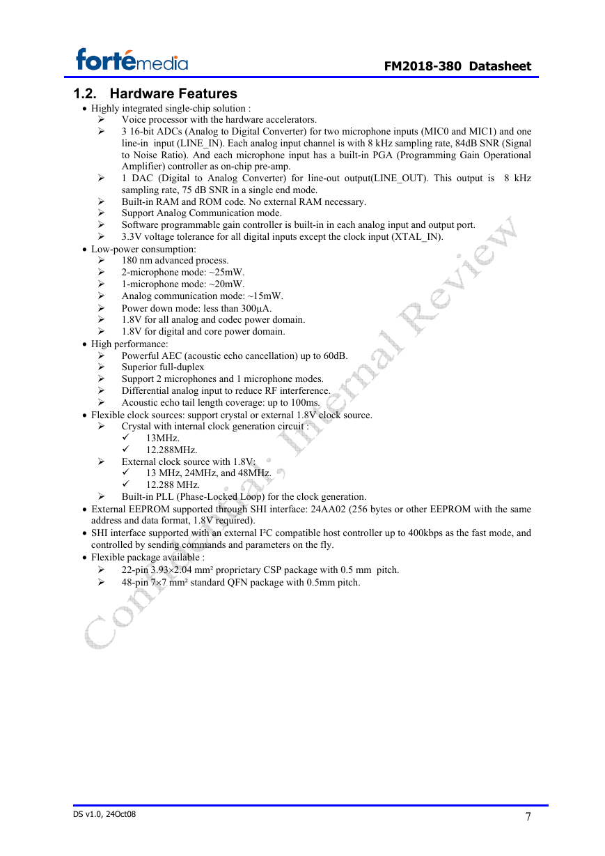
Voice processor with the hardware accelerators.
3 16-bit ADCs (Analog to Digital Converter) for two microphone inputs (MIC0 and MIC1) and one
line-in input (LINE_IN). Each analog input channel is with 8 kHz sampling rate, 84dB SNR (Signal
to Noise Ratio). And each microphone input has a built-in PGA (Programming Gain Operational
Amplifier) controller as on-chip pre-amp.
1 DAC (Digital to Analog Converter) for line-out output(LINE_OUT). This output is 8 kHz
sampling rate, 75 dB SNR in a single end mode.
Built-in RAM and ROM code. No external RAM necessary.
Support Analog Communication mode.
Software programmable gain controller is built-in in each analog input and output port.
3.3V voltage tolerance for all digital inputs except the clock input (XTAL_IN).
• Low-power consumption:
180 nm advanced process.
2-microphone mode: ~25mW.
1-microphone mode: ~20mW.
Analog communication mode: ~15mW.
Power down mode: less than 300μA.
1.8V for all analog and codec power domain.
1.8V for digital and core power domain.
• High performance:
Powerful AEC (acoustic echo cancellation) up to 60dB.
Superior full-duplex
Support 2 microphones and 1 microphone modes.
Differential analog input to reduce RF interference.
Acoustic echo tail length coverage: up to 100ms.
• Flexible clock sources: support crystal or external 1.8V clock source.
Crystal with internal clock generation circuit :
13MHz.
12.288MHz.
External clock source with 1.8V:
13 MHz, 24MHz, and 48MHz.
12.288 MHz.
Built-in PLL (Phase-Locked Loop) for the clock generation.
• External EEPROM supported through SHI interface: 24AA02 (256 bytes or other EEPROM with the same
address and data format, 1.8V required).
• SHI interface supported with an external I²C compatible host controller up to 400kbps as the fast mode, and
controlled by sending commands and parameters on the fly.
• Flexible package available :
22-pin 3.93×2.04 mm² proprietary CSP package with 0.5 mm pitch.
48-pin 7×7 mm² standard QFN package with 0.5mm pitch.
DS v1.0, 24Oct08
7
�
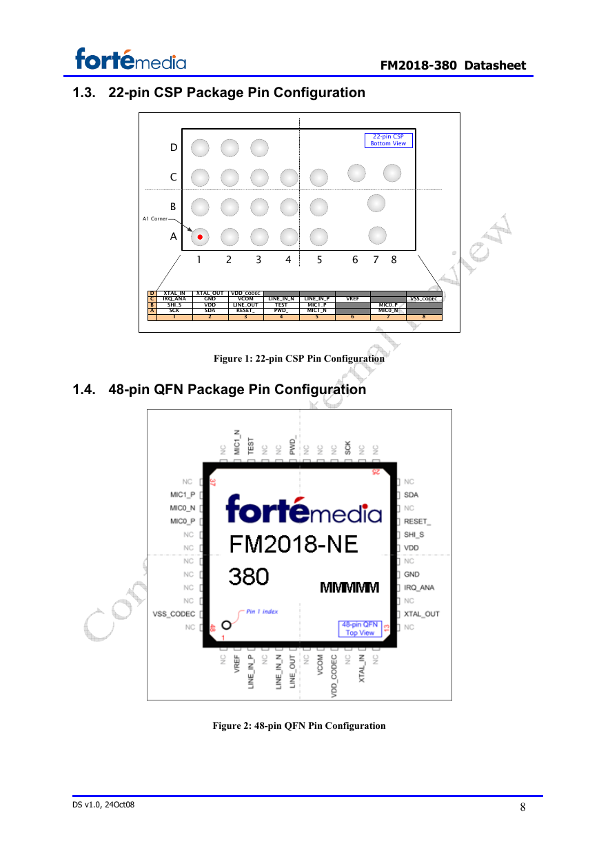
1.3. 22-pin CSP Package Pin Configuration
FM2018-380 Datasheet
22-pin CSP
Bottom View
D
C
B
A
A1 Corner
1
2
3
4
5
6
7 8
D
C
B
A
XTAL_IN
IRQ_ANA
SHI_S
SCK
1
XTAL_OUT
VDD_CODEC
GND
VDD
SDA
2
VCOM
LINE_OUT
RESET_
3
LINE_IN_N
LINE_IN_P
VREF
VSS_CODEC
TEST
PWD_
4
MIC1_P
MIC1_N
5
MIC0_P
MIC0_N
7
6
8
Figure 1: 22-pin CSP Pin Configuration
1.4. 48-pin QFN Package Pin Configuration
Figure 2: 48-pin QFN Pin Configuration
DS v1.0, 24Oct08
8
�



 2023年江西萍乡中考道德与法治真题及答案.doc
 2012年重庆南川中考生物真题及答案.doc
 2013年江西师范大学地理学综合及文艺理论基础考研真题.doc
 2020年四川甘孜小升初语文真题及答案I卷.doc
 2020年注册岩土工程师专业基础考试真题及答案.doc
 2023-2024学年福建省厦门市九年级上学期数学月考试题及答案.doc
 2021-2022学年辽宁省沈阳市大东区九年级上学期语文期末试题及答案.doc
 2022-2023学年北京东城区初三第一学期物理期末试卷及答案.doc
 2018上半年江西教师资格初中地理学科知识与教学能力真题及答案.doc
 2012年河北国家公务员申论考试真题及答案-省级.doc
 2020-2021学年江苏省扬州市江都区邵樊片九年级上学期数学第一次质量检测试题及答案.doc
 2022下半年黑龙江教师资格证中学综合素质真题及答案.doc