Workshop 6
Crack Growth in a Three-point Bend Specimen
using XFEM
Introduction
In this workshop we consider crack growth in the three-point bend specimen studied in
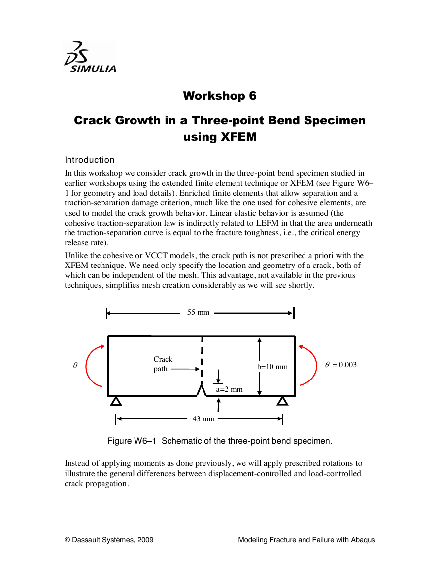
earlier workshops using the extended finite element technique or XFEM (see Figure W6–
1 for geometry and load details). Enriched finite elements that allow separation and a
traction-separation damage criterion, much like the one used for cohesive elements, are
used to model the crack growth behavior. Linear elastic behavior is assumed (the
cohesive traction-separation law is indirectly related to LEFM in that the area underneath
the traction-separation curve is equal to the fracture toughness, i.e., the critical energy
release rate).
Unlike the cohesive or VCCT models, the crack path is not prescribed a priori with the
XFEM technique. We need only specify the location and geometry of a crack, both of
which can be independent of the mesh. This advantage, not available in the previous
techniques, simplifies mesh creation considerably as we will see shortly.
55 mm
Crack
path
b=10 mm
= 0.003
a=2 mm
43 mm
Figure W6–1 Schematic of the three-point bend specimen.
Instead of applying moments as done previously, we will apply prescribed rotations to
illustrate the general differences between displacement-controlled and load-controlled
crack propagation.
© Dassault Systèmes, 2009
Modeling Fracture and Failure with Abaqus
�
Preliminaries
W6.2
1. Enter the working directory for this workshop: ../fracture/bending
2. Open the model database file created earlier (three-point-bend.cae).
We will slightly modify the geometry of the plate and create a separate part to specify the
crack location. Then we will study the crack growth in response to an applied rotation.
The load at which the crack begins to grow will be compared with the ones obtained from
the cohesive and the VCCT models.
Before continuing, copy the model named unfocused to one named xfem. If you did not
complete the exercises with the unfocused mesh in Workshop 1, simply copy any of your
models from Workshop 1 to the new name given above. In the new model, follow the
instructions given in Workshop 1 for deleting the circular partition before proceeding.
The instructions that follow apply to the xfem model.
Editing the geometry
We will first delete the partition on the face that represented the crack in the original
model. In the Model Tree, expand the part named plate for the model named xfem. In the
Features container, click MB3 on the Partition face-1 feature and select Delete from
the menu that appears.
Deleting obsolete attributes
The deletion of the face partition in the previous step deleted the mesh seam and the
sharp crack that existed in the original model. Thus, any model attributes associated with
these must also be deleted.
1. In the Model Tree, expand the Engineering Features container underneath the
Assembly. Expand the Cracks container and click MB3 on Crack-1. In the
menu that appears, select Delete.
2. In the Model Tree, expand the History Output Requests container. Delete the
output requests associated with the sharp crack (H-Output-2 and H-Output-3).
Creating an XFEM crack
To specify the location and geometry of an XFEM crack that is independent of the mesh,
we need a geometric feature in the assembly that can be selected in Abaqus/CAE.
Instead of creating a partition as we did before, we will now create a separate wire part
and instance it in the assembly. This part will represent the crack.
1. In the Model Tree, open the container corresponding to the model named xfem
and double-click Parts to create a deformable 2D wire-based part named crack
with an approximate size of 20.
2. Using the Create lines: Connected tool
sketch a 2mm long vertical line
starting from the origin going upwards. Click Done to exit the sketcher.
3. Open the Assembly container in the Model Tree and double-click Instances to
create a dependent instance of the part named crack. The instance will appear
superimposed on the plate’s left vertical edge.
© Dassault Systèmes, 2009
Modeling Fracture and Failure with Abaqus
�
4. From the main menu bar in the in the Assembly module, select
W6.3
Instance→Translate. Select the crack instance in the viewport and click Done.
5. Enter (0.0,0.0) and (27.5,0.0) as the start and the end points for the
translation vector, respectively. This will move the part to the desired location.
Confirm the current location by clicking OK in the prompt area.
We can now proceed to create an XFEM crack feature.
1. Switch to the Interaction module.
2. From the main menu bar, select Special →Crack→Create.
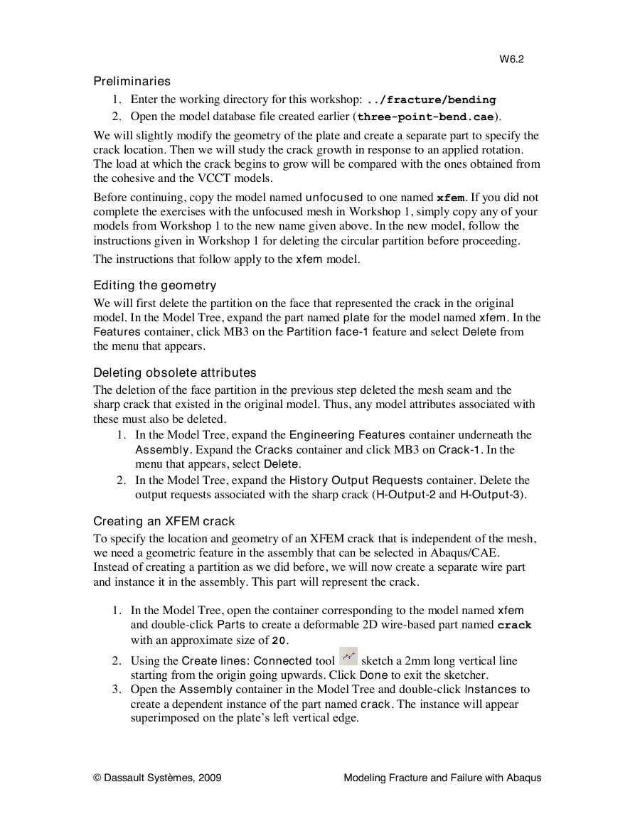
3. In the dialog box that appears, select XFEM as the type as shown in Figure W6–2,
and click Continue.
Figure W6–2 Create Crack dialog box.
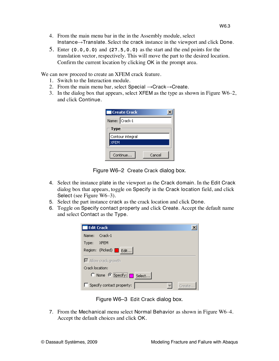
4. Select the instance plate in the viewport as the Crack domain. In the Edit Crack
dialog box that appears, toggle on Specify in the Crack location field, and click
Select (see Figure W6–3).
5. Select the part instance crack as the crack location and click Done.
6. Toggle on Specify contact property and click Create. Accept the default name
and select Contact as the Type.
Figure W6–3 Edit Crack dialog box.
7. From the Mechanical menu select Normal Behavior as shown in Figure W6–4.
Accept the default choices and click OK.
© Dassault Systèmes, 2009
Modeling Fracture and Failure with Abaqus
�
W6.4
Figure W6–4 Edit Contact Property dialog box.
8. Click OK in the Edit Crack dialog box. This completes the definition of the
XFEM crack.
This method of specifying the crack location and geometry is very useful in cases where
the crack geometry is complex. One can easily create a separate part and instance it in the
assembly without having to create numerous partitions in the existing part, which would
introduce difficulties in creating the mesh.
Edit Material Properties
We must include damage initiation and damage evolution criteria to model failure.
1. In the Model Tree, double-click steel in the Materials container to edit the
material properties.
2. Define damage initiation using the Maxps criterion (Mechanical→Damage for
Traction Separation Laws→Maxps Damage). Enter 100 in the data field.
Note: We used 175 for the Quads criterion in the cohesive models. One can arrive
at this value based on a simple calibration study. Usually, we know KIc or Jc from
experiments. For a given geometry, a study involving a focused mesh with elements
that capture the singularity at the crack-tip will give us the load or displacement
required to reach these critical values. Then, by trial and error, we calibrate the
cohesive parameters such as the maximum stress and penalty stiffness, so that the
elements fail at the appropriate value of applied load or displacement. Since XFEM
and cohesive zone methods employ different formulations, the damage parameters
differ between them. It is also important to be cautious about the fracture criterion
itself before using damage parameters from one formulation in another, because not
all the fracture formulations support all the fracture criteria.
3. Define damage evolution using the energy criterion (select Damage Evolution
from the list of Suboptions in the material editor). In the suboption editor, select
Energy as the type, BK as the mixed mode behavior, and set the power to 2.284.
Enter 0.1 in each of the data fields.
© Dassault Systèmes, 2009
Modeling Fracture and Failure with Abaqus
�
Step definition and output
W6.5
The step definition will be edited to adjust the time incrementation parameters and
include nonlinear effects to aid convergence. The applied rotation and resulting reaction
moment at one of the reference points will be written as history data to the output
database file to evaluate the moment-rotation response and detect the onset of crack
growth.
1. In the Model Tree, expand the Steps container and double-click Step-1.
2. In the Basic tabbed page of the step editor, toggle on Nlgeom.
3. To aid convergence if the specimen were to break in half, use automatic
stabilization with a constant damping factor equal to 0.0001. Toggle off adaptive
stabilization.
4. Set the maximum number of increments to 250, the initial time increment size to
0.01, the minimum time increment size to 1.e-8, and the maximum time
increment size to 0.01.
5. Write history output of the variables UR3, CM3 and RM3 for the set right-refPt to
the output database file.
6. Edit the default field output request to include PHISLM (level set value phi) from
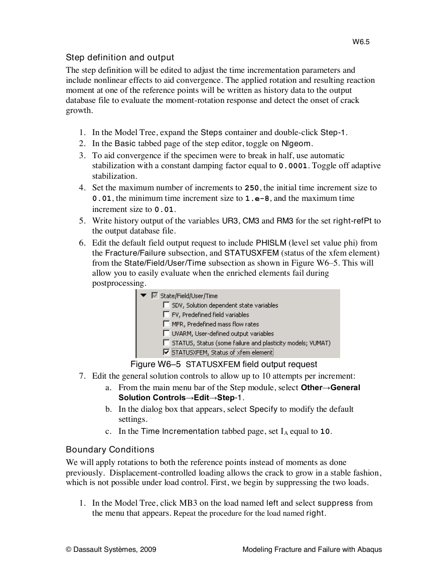
the Fracture/Failure subsection, and STATUSXFEM (status of the xfem element)
from the State/Field/User/Time subsection as shown in Figure W6–5. This will
allow you to easily evaluate when the enriched elements fail during
postprocessing.
Figure W6–5 STATUSXFEM field output request
7. Edit the general solution controls to allow up to 10 attempts per increment:
a. From the main menu bar of the Step module, select Other→General
Solution Controls→Edit→Step-1.
b. In the dialog box that appears, select Specify to modify the default
settings.
c. In the Time Incrementation tabbed page, set IA equal to 10.
Boundary Conditions
We will apply rotations to both the reference points instead of moments as done
previously. Displacement-controlled loading allows the crack to grow in a stable fashion,
which is not possible under load control. First, we begin by suppressing the two loads.
1. In the Model Tree, click MB3 on the load named left and select suppress from
the menu that appears. Repeat the procedure for the load named right.
© Dassault Systèmes, 2009
Modeling Fracture and Failure with Abaqus
�
W6.6
2. Double-click the BCs container to create a new boundary condition named left-
rotation to be applied during Step-1. Choose Displacement/Rotation as the
type and click Continue.
3. Choose the set left-refPT as the location, and set UR3 to -0.003.
4. Using the same procedure, create another boundary condition named right-
rotation applied to the set right-refPT, and specify UR3 to be 0.003.
5. Leave the previously defined boundary condition named right unchanged.
6. Click MB3 on the boundary condition named left and click Edit. Uncheck the
label for U1 to remove the constraint in the X-direction, which was used earlier to
prevent rigid body motion. We will prevent it through a constraint equation in this
model as discussed below.
Constraints
The constraints defined in the previous workshops are needed for this model and we will
leave them unaltered. In the cohesive and VCCT models, there was no ambiguity
regarding the crack propagation direction as it is restricted to the mid-plane a priori; but
in the XFEM model, the crack path can change during the simulation based on the
direction of the maximum principal stress. Though the loading and geometry are
perfectly symmetric, small perturbations in the solution can cause the crack to deflect if
the principal stress directions rotate slightly (they will remain parallel to the global CSYS
in the absence of perturbations). To retain the simplicity of the problem and to compare
the XFEM solution with the cohesive and the VCCT models, we enforce an additional
symmetry constraint such that the horizontal displacements of the centers of the left and
right edges are equal and opposite. This eliminates any numerical instabilities in the
model and facilitates Mode I crack propagation.
1. In the Model Tree double-click Constraints to create a new constraint named
Equation, and select Equation as the type.
2. In the first row, set the Coefficient to 1, select left-refPT in the Set Name field
and enter 1 in the DOF field.
3. Enter the same values for the Coefficient and DOF in the second row while
selecting right-refPT in the Set Name field.
4. Click OK.
Meshing
The part will be meshed with first-order reduced integration plane strain elements.
1. Switch to the Mesh module.
2. From the main menu bar, select Mesh→Controls. Assign Quad as the Element
Shape and select the Structured technique. Assign CPE4R elements to these
regions (Mesh→Element Type).
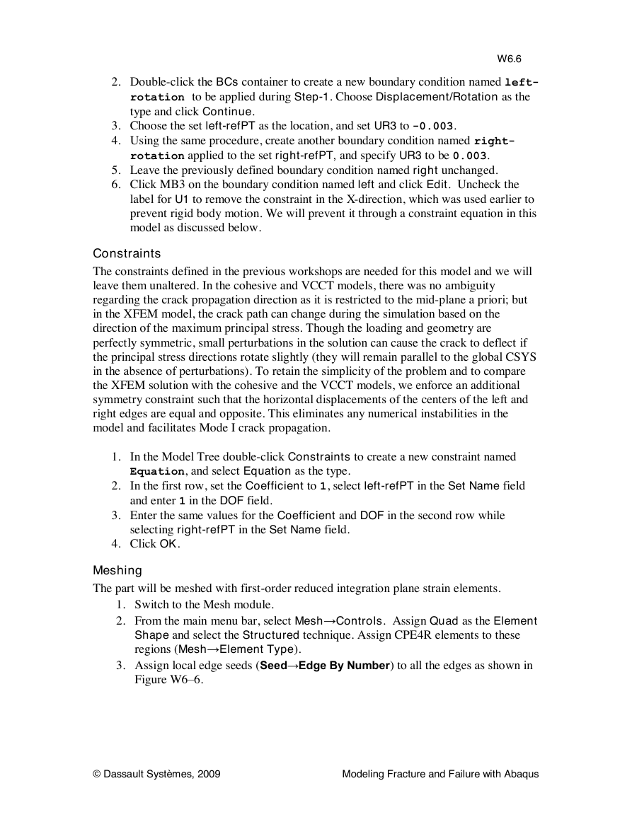
3. Assign local edge seeds (Seed→Edge By Number) to all the edges as shown in
Figure W6–6.
© Dassault Systèmes, 2009
Modeling Fracture and Failure with Abaqus
�
15
12
87
111
W6.7
15
12
Figure W6–6 Local edge seeds
4. Generate the mesh (Mesh→Instance).
Job
1. In the Model Tree, double-click Jobs to create a job for this model. Name the
job xfem-3pt-bend.
2. Save your model database.
3. Click MB3 on the job name and select Submit from the menu that appears. In
the same menu, you may also select Monitor to monitor the progress of the job
and Results to automatically open the output database file for this job (xfem-
3pt-bend.odb) in the Visualization module.
Results
When the job is complete, open xfem-3pt-bend.odb in the Visualization module.
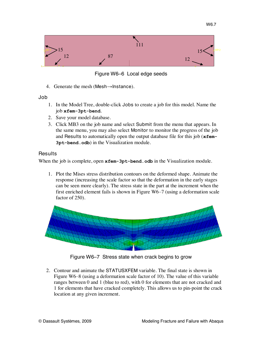
1. Plot the Mises stress distribution contours on the deformed shape. Animate the
response (increasing the scale factor so that the deformation in the early stages
can be seen more clearly). The stress state in the part at the increment when the
first enriched element fails is shown in Figure W6–7 (using a deformation scale
factor of 250).
Figure W6–7 Stress state when crack begins to grow
2. Contour and animate the STATUSXFEM variable. The final state is shown in
Figure W6–8 (using a deformation scale factor of 10). The value of this variable
ranges between 0 and 1 (blue to red), with 0 for elements that are not cracked and
1 for elements that have cracked completely. This allows us to pin-point the crack
location at any given increment.
© Dassault Systèmes, 2009
Modeling Fracture and Failure with Abaqus
�
W6.8
Figure W6–8 Final deformed shape with contour of STATUSXFEM
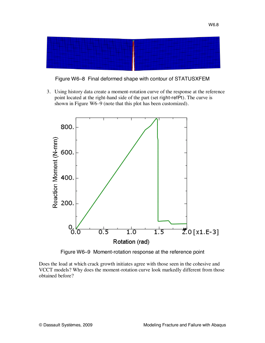
3. Using history data create a moment-rotation curve of the response at the reference
point located at the right-hand side of the part (set right-refPt). The curve is
shown in Figure W6–9 (note that this plot has been customized).
Figure W6–9 Moment-rotation response at the reference point
Does the load at which crack growth initiates agree with those seen in the cohesive and
VCCT models? Why does the moment-rotation curve look markedly different from those
obtained before?
© Dassault Systèmes, 2009
Modeling Fracture and Failure with Abaqus
�



 2023年江西萍乡中考道德与法治真题及答案.doc
 2012年重庆南川中考生物真题及答案.doc
 2013年江西师范大学地理学综合及文艺理论基础考研真题.doc
 2020年四川甘孜小升初语文真题及答案I卷.doc
 2020年注册岩土工程师专业基础考试真题及答案.doc
 2023-2024学年福建省厦门市九年级上学期数学月考试题及答案.doc
 2021-2022学年辽宁省沈阳市大东区九年级上学期语文期末试题及答案.doc
 2022-2023学年北京东城区初三第一学期物理期末试卷及答案.doc
 2018上半年江西教师资格初中地理学科知识与教学能力真题及答案.doc
 2012年河北国家公务员申论考试真题及答案-省级.doc
 2020-2021学年江苏省扬州市江都区邵樊片九年级上学期数学第一次质量检测试题及答案.doc
 2022下半年黑龙江教师资格证中学综合素质真题及答案.doc