WINNER II
D1.1.2 V1.2
IST-4-027756 WINNER II
D1.1.2 V1.2
WINNER II Channel Models
Part I Channel Models
Contractual Date of Delivery to the CEC: 30/09/2007
Actual Date of Delivery to the CEC: 30/09/2007
(updated 04/02/2008)
Author(s):
Pekka Kyösti, Juha Meinilä, Lassi Hentilä, Xiongwen Zhao, Tommi
Jämsä, Christian Schneider, Milan Narandzić, Marko Milojević, Aihua
Hong, Juha Ylitalo, Veli-Matti Holappa, Mikko Alatossava, Robert
Bultitude, Yvo de Jong, Terhi Rautiainen
Participant(s):
Workpackage:
EBITG, TUI, UOULU, CU/CRC, NOKIA
WP1 Channel Model
Estimated person months:
Security:
Nature:
Version:
Total number of pages:
62
PU
R
1.1
82
Abstract:
This deliverable describes WINNER II channel models for link and system level simulations. Both
generic and clustered delay line models are defined for selected propagation scenarios.
Keyword list: Channel modelling, radio channel, propagation scenario, channel sounder, cluster,
polarisation, measurements, delay spread, angle spread, MIMO, fading
Disclaimer: The channel models described in this deliverable are based on a literature survey and
measurements performed during this project. The authors are not responsible for any loss, damage or
expenses caused by potential errors or inaccuracies in the models or in the deliverable.
Page 1 (82)
�
WINNER II
D1.1.2 V1.2
Executive Summary
This deliverable presents WINNER II channel models for link level and system level simulations of local
area, metropolitan area, and wide area wireless communication systems. The models have been evolved
from the WINNER I channel models described in WINNER I deliverable D5.4 and WINNER II interim
channel models described in deliverable D1.1.1. The covered propagation scenarios are indoor office,
large indoor hall, indoor-to-outdoor, urban micro-cell, bad urban micro-cell, outdoor-to-indoor, stationary
feeder, suburban macro-cell, urban macro-cell, rural macro-cell, and rural moving networks.
The generic WINNER II channel model follows a geometry-based stochastic channel modelling
approach, which allows creating of an arbitrary double directional radio channel model. The channel
models are antenna independent, i.e., different antenna configurations and different element patterns can
be inserted. The channel parameters are determined stochastically, based on statistical distributions
extracted from channel measurement. The distributions are defined for, e.g., delay spread, delay values,
angle spread, shadow fading, and cross-polarisation ratio. For each channel snapshot the channel
parameters are calculated from the distributions. Channel realisations are generated by summing
contributions of rays with specific channel parameters like delay, power, angle-of-arrival and angle-of-
departure. Different scenarios are modelled by using the same approach, but different parameters. The
parameter tables for each scenario are included in this deliverable.
Clustered delay line (CDL) models with fixed large-scale and small-scale parameters have also been
created for calibration and comparison of different simulations. The parameters of the CDL models are
based on expectation values of the generic models.
Several measurement campaigns provide the background for the parameterisation of the propagation
scenarios for both line-of-sight (LOS) and non-LOS (NLOS) conditions. These measurements were
conducted by seven partners with different devices. The developed models are based on both literature
and extensive measurement campaigns that have been carried out within the WINNER I and WINNER II
projects.
The novel features of the WINNER models are its parameterisation, using of the same modelling
approach for both indoor and outdoor environments, new scenarios like outdoor-to-indoor and indoor-to-
outdoor, elevation in indoor scenarios, smooth time (and space) evolution of large-scale and small-scale
channel parameters (including cross-correlations), and scenario-dependent polarisation modelling. The
models are scalable from a single single-input-single-output (SISO) or multiple-input-multiple-output
(MIMO) link to a multi-link MIMO scenario including polarisation among other radio channel
dimensions.
WINNER II channel models can be used in link level and system level performance evaluation of
wireless systems, as well as comparison of different algorithms, technologies and products. The models
can be applied not only to WINNER II system, but also any other wireless system operating in 2 – 6 GHz
frequency range with up to 100 MHz RF bandwidth. The models supports multi-antenna technologies,
polarisation, multi-user, multi-cell, and multi-hop networks.
This report is divided into two parts. The first part defines the channel model structure and parameters.
The second part (separate volume) contains more detailed information about channel measurements and
analysis.
Page 2 (82)
�
WINNER II
Authors
Partner
EBITG
EBITG
EBITG
EBITG
EBITG
UOULU/EBITG
UOULU
D1.1.2 V1.2
Name
Phone / Fax / e-mail
Pekka Kyösti
Phone: +358 40 344 2000
Fax: +358 8 551 4344
e-mail: firstname.lastname@elektrobit.com
Juha Meinilä
Phone: +358 40 344 2000
Fax: +
e-mail: firstname.lastname@elektrobit.com
Tommi Jämsä
Phone: +358 40 344 2000
Fax: +358 8 551 4344
e-mail: firstname.lastname@elektrobit.com
Xiongwen Zhao
Phone: +358 40 344 2000
Fax: +358 9 2561014
e-mail: firstname.lastname@elektrobit.com
Lassi Hentilä
Phone: +358 40 344 2000
Fax: +358 8 551 4344
e-mail: firstname.lastname@elektrobit.com
Juha Ylitalo
Phone: +358 40 344 3352
Fax: +358 8 551 4344
e-mail: firstname.lastname@elektrobit.com
Mikko Alatossava
Phone: +358 8 814 7638
Fax: +358 8 553 2845
e-mail: mikko.alatossava@ee.oulu.fi
Page 3 (82)
�
WINNER II
D1.1.2 V1.2
UOULU
TUI
TUI
TUI
TUI
TUI
CRC
CRC
NOK
Veli-Matti Holappa
Phone: +358 8 814 2890
Fax: +358 8 553 2845
e-mail: crimson@ee.oulu.fi
Milan Narandžić
Phone: + 49 3677 69 3722
Fax: + 49 3677 69 1113
e-mail: milan.narandzic@tu-ilmenau.de
Aihua Hong
Phone: + 49 3677 69 1157
Fax: + 49 3677 69 1113
e-mail: aihua.hong@tu-ilmenau.de
Marko Milojević
Phone: + 49 3677 69 2673
Fax: + 49 3677 69 1195
e-mail: marko.milojevic@tu-ilmenau.de
Christian Schneider
Phone: + 49 3677 69 1157
Fax: + 49 3677 69 1113
e-mail: christian.schneider@tu-ilmenau.de
Gerd Sommerkorn
Phone: + 49 3677 69 1115
Fax: + 49 3677 69 1113
e-mail: gerd.sommerkorn@tu-ilmenau.de
Robert Bultitude
Phone: 1-613-98-2775
Fax: 1-613-990-7987
e-mail: robert.bultitude@crc.ca
Yvo de Jong
Phone: 1-603-990-9235
Fax: 1-613-990-6339
e-mail: yvo.dejong@crc.ca
Terhi Rautiainen
Phone: +358 50 4837218
Fax: + 358 7180 36857
e-mail: terhi.rautiainen@nokia.com
Page 4 (82)
�
WINNER II
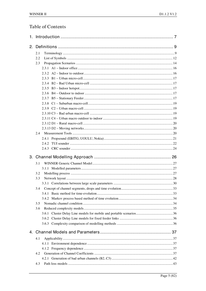
Table of Contents
D1.1.2 V1.2
1. Introduction ................................................................................................. 7
2. Definitions ................................................................................................... 9
2.1 Terminology ................................................................................................................................ 9
2.2 List of Symbols ......................................................................................................................... 12
2.3 Propagation Scenarios ............................................................................................................... 14
2.3.1 A1 – Indoor office............................................................................................................. 16
2.3.2 A2 – Indoor to outdoor...................................................................................................... 16
2.3.3 B1 – Urban micro-cell....................................................................................................... 17
2.3.4 B2 – Bad Urban micro-cell ............................................................................................... 17
2.3.5 B3 – Indoor hotspot........................................................................................................... 17
2.3.6 B4 – Outdoor to indoor ..................................................................................................... 17
2.3.7 B5 – Stationary Feeder...................................................................................................... 17
2.3.8 C1 – Suburban macro-cell................................................................................................. 19
2.3.9 C2 – Urban macro-cell ...................................................................................................... 19
2.3.10 C3 – Bad urban macro-cell ............................................................................................... 19
2.3.11 C4 – Urban macro outdoor to indoor ................................................................................ 19
2.3.12 D1 – Rural macro-cell....................................................................................................... 20
2.3.13 D2 – Moving networks...................................................................................................... 20
2.4 Measurement Tools ................................................................................................................... 20
2.4.1 Propsound (EBITG, UOULU, Nokia)............................................................................... 21
2.4.2 TUI sounder ...................................................................................................................... 22
2.4.3 CRC sounder ..................................................................................................................... 24
3. Channel Modelling Approach .................................................................. 26
3.1 WINNER Generic Channel Model............................................................................................ 27
3.1.1 Modelled parameters......................................................................................................... 27
3.2 Modelling process ..................................................................................................................... 27
3.3 Network layout .......................................................................................................................... 28
3.3.1 Correlations between large scale parameters .................................................................... 30
3.4 Concept of channel segments, drops and time evolution........................................................... 33
3.4.1 Basic method for time-evolution....................................................................................... 33
3.4.2 Markov process based method of time evolution.............................................................. 34
3.5 Nomadic channel condition ....................................................................................................... 34
3.6 Reduced complexity models...................................................................................................... 35
3.6.1 Cluster Delay Line models for mobile and portable scenarios.......................................... 36
3.6.2 Cluster Delay Line models for fixed feeder links ............................................................. 36
3.6.3 Complexity comparison of modelling methods ................................................................ 36
4. Channel Models and Parameters............................................................. 37
4.1 Applicability.............................................................................................................................. 37
4.1.1 Environment dependence .................................................................................................. 37
4.1.2 Frequency dependence ...................................................................................................... 37
4.2 Generation of Channel Coefficients .......................................................................................... 37
4.2.1 Generation of bad urban channels (B2, C3) ...................................................................... 42
4.3 Path loss models ........................................................................................................................ 43
Page 5 (82)
�
WINNER II
D1.1.2 V1.2
4.3.1 Transitions between LOS/NLOS ...................................................................................... 46
4.4 Parameter tables for generic models.......................................................................................... 46
4.4.1 Reference output values .................................................................................................... 48
4.5 CDL Models .............................................................................................................................. 49
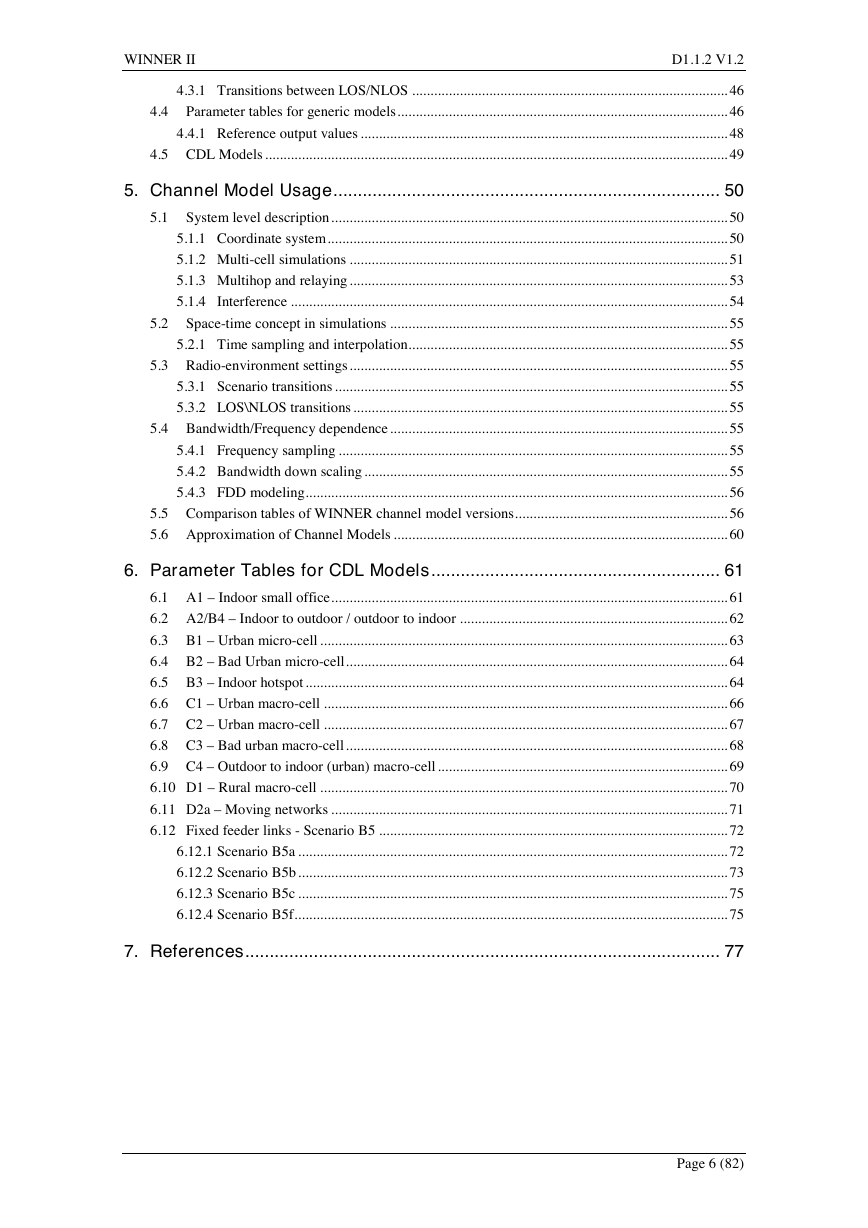
5. Channel Model Usage............................................................................... 50
5.1 System level description............................................................................................................ 50
5.1.1 Coordinate system............................................................................................................. 50
5.1.2 Multi-cell simulations ....................................................................................................... 51
5.1.3 Multihop and relaying ....................................................................................................... 53
5.1.4 Interference ....................................................................................................................... 54
5.2 Space-time concept in simulations ............................................................................................ 55
5.2.1 Time sampling and interpolation....................................................................................... 55
5.3 Radio-environment settings....................................................................................................... 55
5.3.1 Scenario transitions ........................................................................................................... 55
5.3.2 LOS\NLOS transitions ...................................................................................................... 55
5.4 Bandwidth/Frequency dependence............................................................................................ 55
5.4.1 Frequency sampling .......................................................................................................... 55
5.4.2 Bandwidth down scaling ................................................................................................... 55
5.4.3 FDD modeling................................................................................................................... 56
5.5 Comparison tables of WINNER channel model versions.......................................................... 56
5.6 Approximation of Channel Models ........................................................................................... 60
6. Parameter Tables for CDL Models........................................................... 61
6.1 A1 – Indoor small office............................................................................................................ 61
6.2 A2/B4 – Indoor to outdoor / outdoor to indoor ......................................................................... 62
6.3 B1 – Urban micro-cell ............................................................................................................... 63
6.4 B2 – Bad Urban micro-cell........................................................................................................ 64
6.5 B3 – Indoor hotspot................................................................................................................... 64
6.6 C1 – Urban macro-cell .............................................................................................................. 66
6.7 C2 – Urban macro-cell .............................................................................................................. 67
6.8 C3 – Bad urban macro-cell........................................................................................................ 68
6.9 C4 – Outdoor to indoor (urban) macro-cell ............................................................................... 69
6.10 D1 – Rural macro-cell ............................................................................................................... 70
6.11 D2a – Moving networks ............................................................................................................ 71
6.12 Fixed feeder links - Scenario B5 ............................................................................................... 72
6.12.1 Scenario B5a ..................................................................................................................... 72
6.12.2 Scenario B5b..................................................................................................................... 73
6.12.3 Scenario B5c ..................................................................................................................... 75
6.12.4 Scenario B5f...................................................................................................................... 75
7. References................................................................................................. 77
Page 6 (82)
�
WINNER II
D1.1.2 V1.2
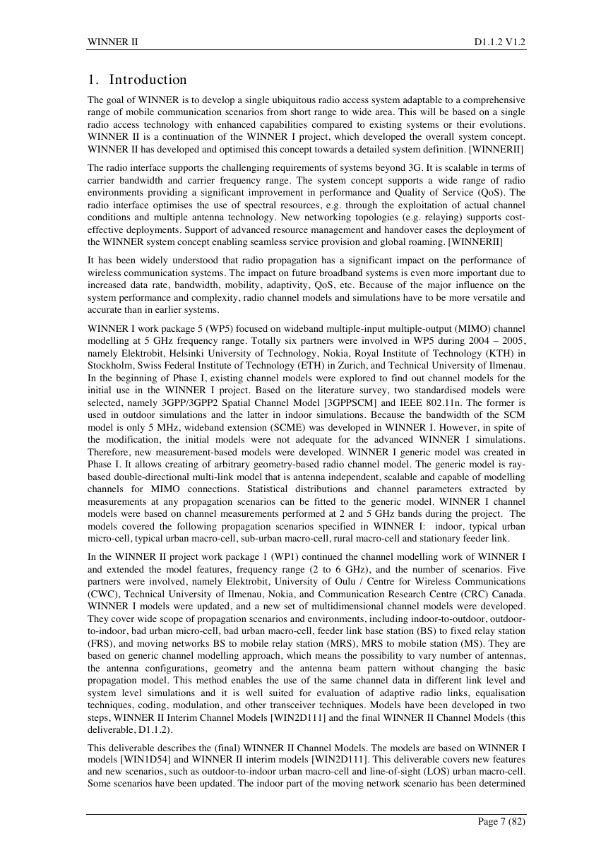
1. Introduction
The goal of WINNER is to develop a single ubiquitous radio access system adaptable to a comprehensive
range of mobile communication scenarios from short range to wide area. This will be based on a single
radio access technology with enhanced capabilities compared to existing systems or their evolutions.
WINNER II is a continuation of the WINNER I project, which developed the overall system concept.
WINNER II has developed and optimised this concept towards a detailed system definition. [WINNERII]
The radio interface supports the challenging requirements of systems beyond 3G. It is scalable in terms of
carrier bandwidth and carrier frequency range. The system concept supports a wide range of radio
environments providing a significant improvement in performance and Quality of Service (QoS). The
radio interface optimises the use of spectral resources, e.g. through the exploitation of actual channel
conditions and multiple antenna technology. New networking topologies (e.g. relaying) supports cost-
effective deployments. Support of advanced resource management and handover eases the deployment of
the WINNER system concept enabling seamless service provision and global roaming. [WINNERII]
It has been widely understood that radio propagation has a significant impact on the performance of
wireless communication systems. The impact on future broadband systems is even more important due to
increased data rate, bandwidth, mobility, adaptivity, QoS, etc. Because of the major influence on the
system performance and complexity, radio channel models and simulations have to be more versatile and
accurate than in earlier systems.
WINNER I work package 5 (WP5) focused on wideband multiple-input multiple-output (MIMO) channel
modelling at 5 GHz frequency range. Totally six partners were involved in WP5 during 2004 – 2005,
namely Elektrobit, Helsinki University of Technology, Nokia, Royal Institute of Technology (KTH) in
Stockholm, Swiss Federal Institute of Technology (ETH) in Zurich, and Technical University of Ilmenau.
In the beginning of Phase I, existing channel models were explored to find out channel models for the
initial use in the WINNER I project. Based on the literature survey, two standardised models were
selected, namely 3GPP/3GPP2 Spatial Channel Model [3GPPSCM] and IEEE 802.11n. The former is
used in outdoor simulations and the latter in indoor simulations. Because the bandwidth of the SCM
model is only 5 MHz, wideband extension (SCME) was developed in WINNER I. However, in spite of
the modification, the initial models were not adequate for the advanced WINNER I simulations.
Therefore, new measurement-based models were developed. WINNER I generic model was created in
Phase I. It allows creating of arbitrary geometry-based radio channel model. The generic model is ray-
based double-directional multi-link model that is antenna independent, scalable and capable of modelling
channels for MIMO connections. Statistical distributions and channel parameters extracted by
measurements at any propagation scenarios can be fitted to the generic model. WINNER I channel
models were based on channel measurements performed at 2 and 5 GHz bands during the project. The
models covered the following propagation scenarios specified in WINNER I: indoor, typical urban
micro-cell, typical urban macro-cell, sub-urban macro-cell, rural macro-cell and stationary feeder link.
In the WINNER II project work package 1 (WP1) continued the channel modelling work of WINNER I
and extended the model features, frequency range (2 to 6 GHz), and the number of scenarios. Five
partners were involved, namely Elektrobit, University of Oulu / Centre for Wireless Communications
(CWC), Technical University of Ilmenau, Nokia, and Communication Research Centre (CRC) Canada.
WINNER I models were updated, and a new set of multidimensional channel models were developed.
They cover wide scope of propagation scenarios and environments, including indoor-to-outdoor, outdoor-
to-indoor, bad urban micro-cell, bad urban macro-cell, feeder link base station (BS) to fixed relay station
(FRS), and moving networks BS to mobile relay station (MRS), MRS to mobile station (MS). They are
based on generic channel modelling approach, which means the possibility to vary number of antennas,
the antenna configurations, geometry and the antenna beam pattern without changing the basic
propagation model. This method enables the use of the same channel data in different link level and
system level simulations and it is well suited for evaluation of adaptive radio links, equalisation
techniques, coding, modulation, and other transceiver techniques. Models have been developed in two
steps, WINNER II Interim Channel Models [WIN2D111] and the final WINNER II Channel Models (this
deliverable, D1.1.2).
This deliverable describes the (final) WINNER II Channel Models. The models are based on WINNER I
models [WIN1D54] and WINNER II interim models [WIN2D111]. This deliverable covers new features
and new scenarios, such as outdoor-to-indoor urban macro-cell and line-of-sight (LOS) urban macro-cell.
Some scenarios have been updated. The indoor part of the moving network scenario has been determined
Page 7 (82)
�
WINNER II
D1.1.2 V1.2
and whole the scenario has been updated considerably, as well as the model for indoor hot-spot. Bad
urban scenarios have also been updated. New features of the WINNER II Channel Models include
modelling of the elevation of rays, treating the LOS component of the channel model as a random
variable, and moving scatterers in fixed connections. The differences in the scenarios Indoor-to-Outdoor
and Outdoor-to-Indoor were noticed to be negligible. Therefore these two scenarios have been merged.
Model parameters have been revised in the cases, where new results have pointed this necessary.
Valuable comments have been received also via standardisation work in various standardisation bodies,
especially in IEEE802.16m and ITU-R/8F. We have taken into account several such change proposals.
Probably most important of them is the tuning of our path-loss models.
During the projects WINNER I and WINNER II the models have been evolved, mainly by adding new
scenarios in the models, but also by including new features. In this process we have tried to conserve the
model parameters from changes as much as possible. However, some changes have been inevitable.
Therefore the models are not exactly the same in this and the earlier deliverables. The propagation
scenarios from WINNER Phase I have been included in this document, partly updated. In WINNER
Phase II the following new propagation scenarios have been created and documented in this document:
indoor-to-outdoor, outdoor-to-indoor, bad urban micro-cell, bad urban macro-cell and moving network
scenario. All the propagation scenarios have been listed and introduced in section 2.3. WINNER I,
WINNER II interim, and WINNER II final models are compared in section 5.5.
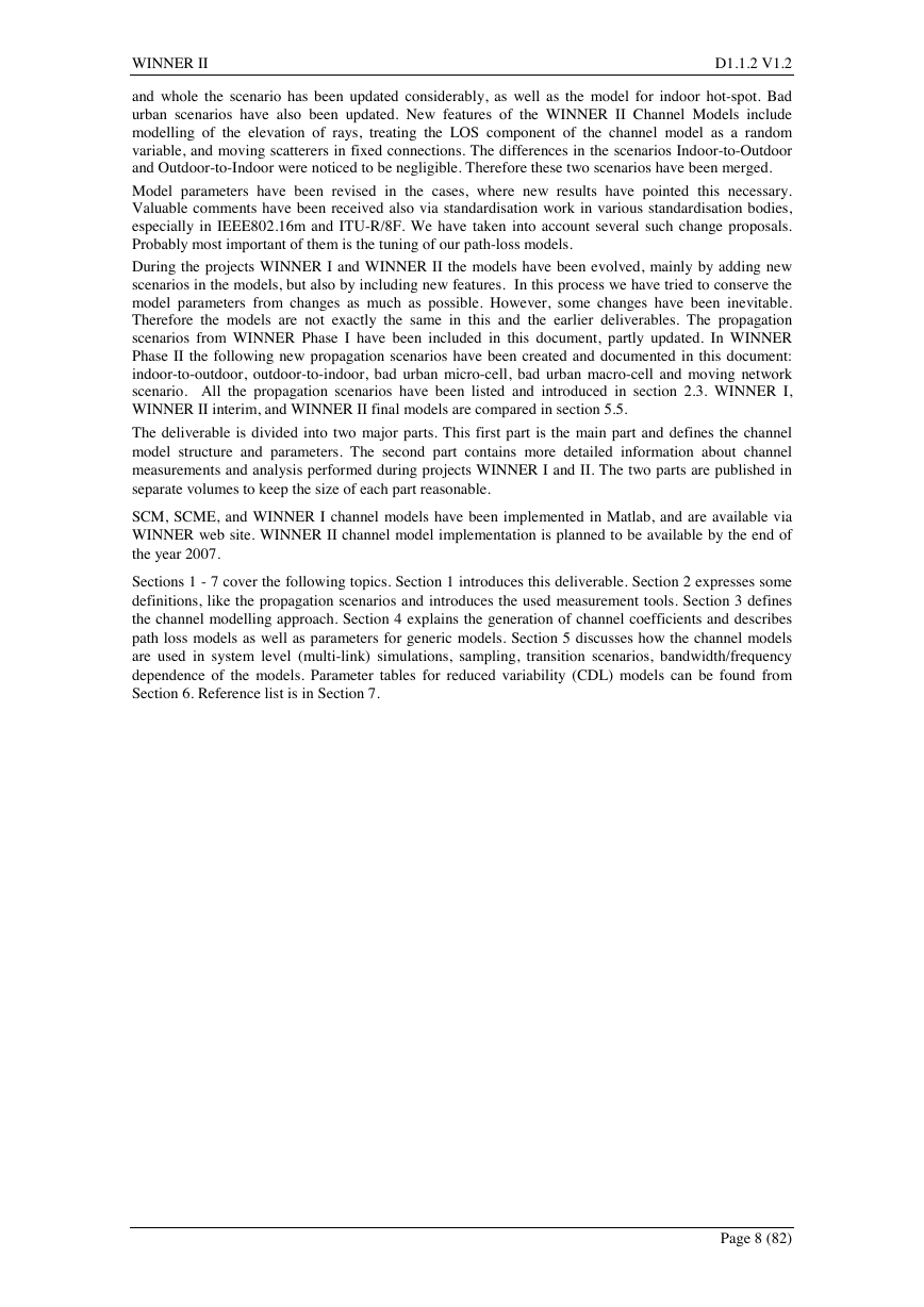
The deliverable is divided into two major parts. This first part is the main part and defines the channel
model structure and parameters. The second part contains more detailed information about channel
measurements and analysis performed during projects WINNER I and II. The two parts are published in
separate volumes to keep the size of each part reasonable.
SCM, SCME, and WINNER I channel models have been implemented in Matlab, and are available via
WINNER web site. WINNER II channel model implementation is planned to be available by the end of
the year 2007.
Sections 1 - 7 cover the following topics. Section 1 introduces this deliverable. Section 2 expresses some
definitions, like the propagation scenarios and introduces the used measurement tools. Section 3 defines
the channel modelling approach. Section 4 explains the generation of channel coefficients and describes
path loss models as well as parameters for generic models. Section 5 discusses how the channel models
are used in system level (multi-link) simulations, sampling, transition scenarios, bandwidth/frequency
dependence of the models. Parameter tables for reduced variability (CDL) models can be found from
Section 6. Reference list is in Section 7.
Page 8 (82)
�


 2023年江西萍乡中考道德与法治真题及答案.doc
 2012年重庆南川中考生物真题及答案.doc
 2013年江西师范大学地理学综合及文艺理论基础考研真题.doc
 2020年四川甘孜小升初语文真题及答案I卷.doc
 2020年注册岩土工程师专业基础考试真题及答案.doc
 2023-2024学年福建省厦门市九年级上学期数学月考试题及答案.doc
 2021-2022学年辽宁省沈阳市大东区九年级上学期语文期末试题及答案.doc
 2022-2023学年北京东城区初三第一学期物理期末试卷及答案.doc
 2018上半年江西教师资格初中地理学科知识与教学能力真题及答案.doc
 2012年河北国家公务员申论考试真题及答案-省级.doc
 2020-2021学年江苏省扬州市江都区邵樊片九年级上学期数学第一次质量检测试题及答案.doc
 2022下半年黑龙江教师资格证中学综合素质真题及答案.doc