790
IEEE Transactions on Consumer Electronics, Vol. 51, No. 3, AUGUST 2005
On Channel Estimation and Equalization in TDS-OFDM based
Terrestrial HDTV Broadcasting System
Bowei Song, Lin Gui, Yunfeng Guan and Wenjun Zhang
Abstract —In TDS-OFDM (Time-Domain Synchronous
Orthogonal Frequency Division Multiplexing)
systems,
pseudonoise (PN) sequences rather than cyclic prefixes are
inserted as guard interval, between consecutive inverse
discrete Fourier transformed (IDFT) symbol blocks. Since the
PN sequences can also be used as training symbols, such
system can provide higher spectrum efficiency. However, due
to non-cyclic property of the signal, the simple channel
estimation and equalization techniques for conventional cyclic
prefixed OFDM (CP-OFDM) can not be applied to TDS-
OFDM. In this paper, we propose a channel estimation and
equalization method for TDS-OFDM. Channel estimation
depends on time domain correlation and iterative interference
cancellation techniques, while equalization is based on tail
cancellation and cyclic restoration algorithm (TCCR). It is
shown that our proposed method can provide satisfactory
performance in TDS-OFDM based terrestrial high-definition
television (HDTV) broadcasting system 1
Index Terms —Channel estimation, Correlation, DMB-T,
Equalization, HDTV, Interference cancellation, OFDM.
I. INTRODUCTION
OFDM system is an attractive technique for broadband
communications. By inserting cyclic prefix (CP) between
different symbols, it can efficiently combat multipath channels
and can be easily demodulated. However, in order to cope with
long delayed multipath, longer CP is need; Furthermore, large
amount of pilots are also inserted into data frames for system
synchronization and channel estimation. These payloads will
dramatically reduce bandwidth efficiency of the system.
In recent years, a technique called time-domain synchronous
OFDM (TDS-OFDM) has received more and more interests. A
typical application of TDS-OFDM is DMB-T system, a
candidate terrestrial HDTV broadcasting standard in China [1-
1 Manuscript received XX 1, 2005. Project supported by National Hi-Tech
Research and Development Program of China (National 863 Program) under
Grant No. 2003AA123310 and National Nature Science Foundation of China
(NSFC) under Grant No. 60332030.
Bowei Song is with the institute of Image Communication and Information
:
Processing, Shanghai Jiao Tong University, Shanghai, China(email
bwsong77@163.com).
Lin Gui is with the institute of Image Communication and Information
:
Processing, Shanghai Jiao Tong University, Shanghai, China(email
guilin@sjtu.edu.cn ).
Yunfeng Guan is with the institute of Image Communication and
Jiao Tong University, Shanghai,
Information Processing, Shanghai
China(email : yfguan69@sjtu.edu.cn ).
Wenjun Zhang is with the institute of Image Communication and
Jiao Tong University, Shanghai,
Information Processing, Shanghai
China(email : zhangwenjun@sjtu.edu.cn).
6]. In stead of CP, PN sequences are inserted as guard
intervals. PN guard intervals can also be used as training
symbols for synchronization and estimation purpose so there is
no additional pilot symbol needed. For this reason, TDS-
OFDM can provide higher system throughput than CP-OFDM.
However, with introducing PN guard interval, the cyclic
property of the signal frame as in CP-OFDM does not hold any
more, so the inter-symbol interference (ISI) is unavoidable.
Neither conventional channel estimation algorithms nor simple
one-tap frequency domain equalizer for CP-OFDM can be
applied to TDS-OFDM directly.
technology
for DMB-T
In this paper, we will discuss the channel estimation and
equalization
system. Channel
estimation is based on time domain correlation and iterative
interference cancellation; for equalization, a technique called
tail cancellation and cyclic restoration (TCCR) is proposed. By
compared with the performance of DVB-T [7], it is shown that
our proposed method can work well in DMB-T system.
This paper is organized as follows: In section II, we briefly
overview the basic structure of the DMB-T system. In section
III, we will discuss the details of channel estimation. After that,
equalization method for DMB-T is proposed in section IV. In
section V, computer simulation is presented and performance
is compared with DVB-T. In section VI, we will conclude this
paper finally.
II. DMB-T SYSTEM DESCRIPTION
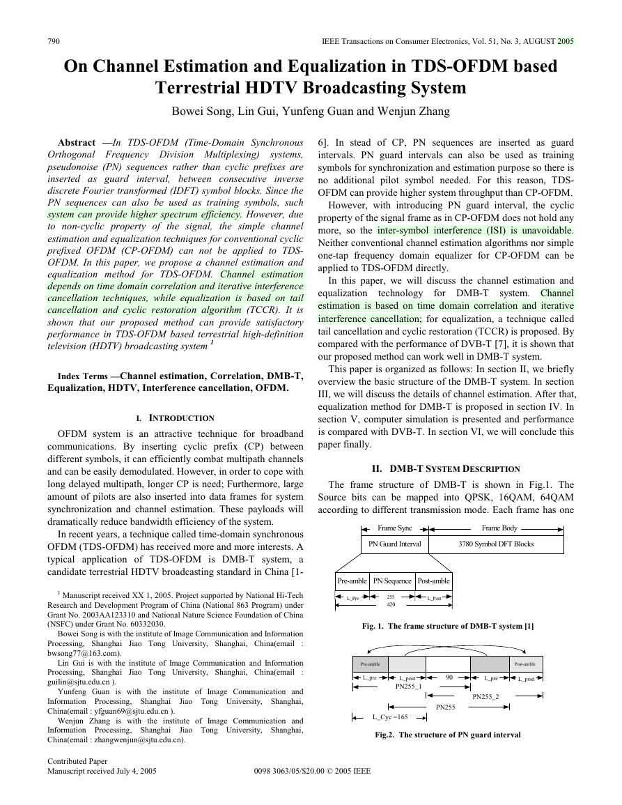
The frame structure of DMB-T is shown in Fig.1. The
Source bits can be mapped into QPSK, 16QAM, 64QAM
according to different transmission mode. Each frame has one
Frame Sync
Frame Body
PN Guard Interval
3780 Symbol DFT Blocks
Pre-amble PN Sequence Post-amble
L_Pre
255
420
L_Post
Fig. 1. The frame structure of DMB-T system [1]
90
Post-amble
L_pre
L_post
PN255_2
PN255
Pre-amble
L_pre
L_post
PN255_1
L_Cyc =165
Fig.2. The structure of PN guard interval
Contributed Paper
Manuscript received July 4, 2005 0098 3063/05/$20.00 © 2005 IEEE
�
791
M is 255 and (⋅)M denotes modular M process. Then
equation (3) can be rewritten as:
L
−
1
M
−
1
τ
( )
a
=
i
0
R n
( )
py
=
=
=
τ
0
−
L
1
=
τ
0
p i p n i
( ) ((
+ −
τ
) )
M
+
R n
( )
pn
(5)
τ
a R n
( )
(
pp
τ
− +
)
R n
( )
pn
, =
n
0,...,
M
−
1
Rpp(n) is the auto-correlation of PN255 and Rpn(n) is cross-
correlation between PN255 and noise. If Rpp(n) is ideal δ
function (impulse function), Rpy(n) is just the estimated
channel impulse response.
However, the auto-correlation of m sequences Rpp(n) is not
ideal δ but with the following value:
R n
( )
pp
=
M
−
1
=
0
i
+
p i p n i
( ) ((
) )
M
=
,
M n=
− , ≠
n
1
0
, =
0
n
0,...,
M
−
1
(6)
There is a direct current value with n≠0 and this will
introduce
interference between different channel paths.
Fortunately, the direct current value (minus one) is relatively
small compared with M, and the interference can be removed
by using following iterative ‘correlation reshape’ process:
1) First, we find the biggest peak value â(τ0) of Rpy(n), τ0
is the location of this correlation peak. We can subtract
the interference by:
(1)
R
py
n R n
( )
( )
=
py
+
τ
a
ˆ(
)
0
M
, =
n
0,...,
M
τ
− ≠
1,
0
n
(7)
2) Then, we will find the second biggest peak value â(τ1)
(1)(n), and subtract the interference of â(τ1) from
of Rpy
(1)(n) again. In general case, after removing
Rpy
interference of several strongest correlation peak value,
we can get satisfactory estimation of channel impulse
response (i is the iteration number):
Frame Sync and one Frame Body. 3780 mapped symbols are
grouped into one OFDM symbol and build up one Frame Body.
A PN guard interval with length 420 is inserted before each
Frame Body as Frame Sync. The detail of PN guard interval is
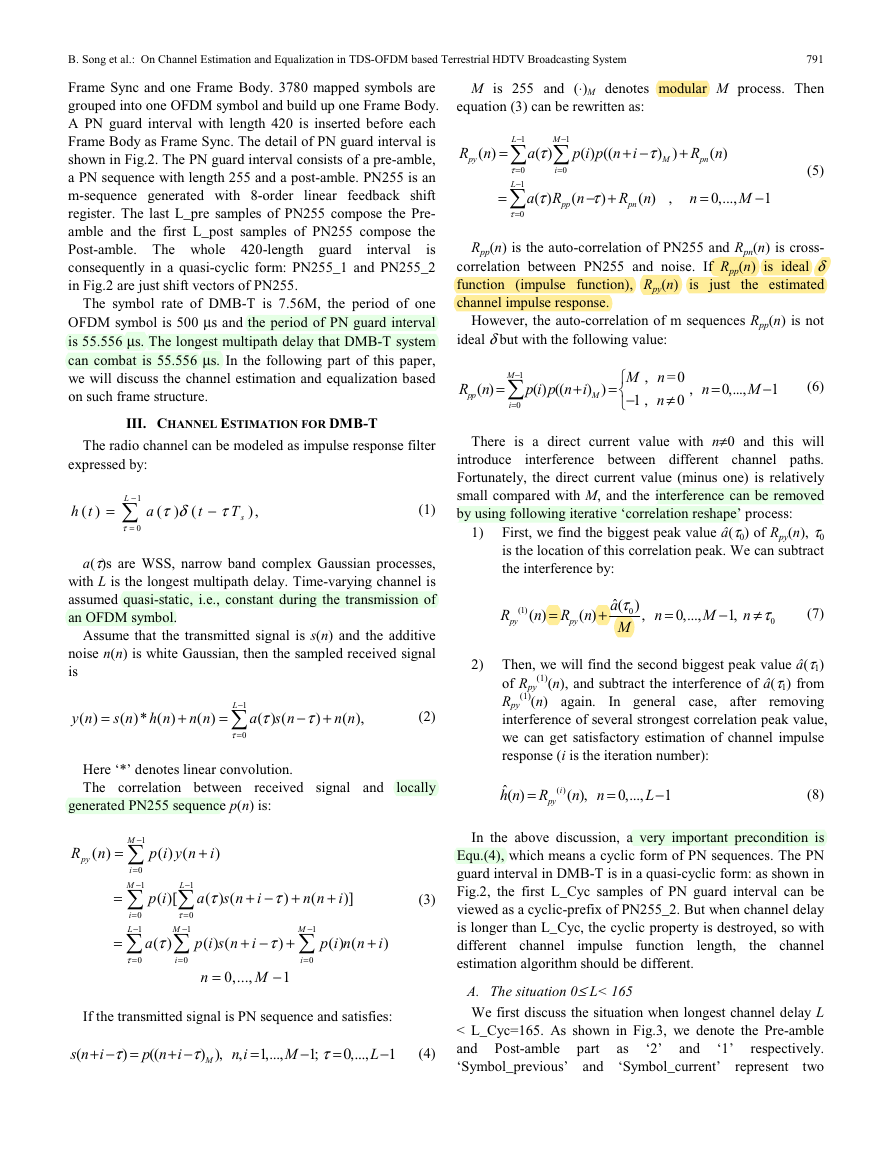
shown in Fig.2. The PN guard interval consists of a pre-amble,
a PN sequence with length 255 and a post-amble. PN255 is an
m-sequence generated with 8-order linear feedback shift
register. The last L_pre samples of PN255 compose the Pre-
amble and the first L_post samples of PN255 compose the
Post-amble. The whole 420-length guard
is
consequently in a quasi-cyclic form: PN255_1 and PN255_2
in Fig.2 are just shift vectors of PN255.
interval
The symbol rate of DMB-T is 7.56M, the period of one
OFDM symbol is 500 μs and the period of PN guard interval
is 55.556 μs. The longest multipath delay that DMB-T system
can combat is 55.556 μs. In the following part of this paper,
we will discuss the channel estimation and equalization based
on such frame structure.
III. CHANNEL ESTIMATION FOR DMB-T
The radio channel can be modeled as impulse response filter
expressed by:
h t
( )
=
L
−
1
τ
=
0
a
τ δ τ
T
(
−
)
(
t
),
s
(1)
a(τ)s are WSS, narrow band complex Gaussian processes,
with L is the longest multipath delay. Time-varying channel is
assumed quasi-static, i.e., constant during the transmission of
an OFDM symbol.
Assume that the transmitted signal is s(n) and the additive
noise n(n) is white Gaussian, then the sampled received signal
is
y n
( )
s n
h n
( )* ( )
τ
s n
( ) (
n n
( ),
n n
( )
(2)
τ
)
=
−
+
=
+
a
−
1
L
τ
=
0
Here ‘*’ denotes linear convolution.
The correlation between received signal and
generated PN255 sequence p(n) is:
R n
( )
py
=
=
=
M
−
1
=
i
0
−
M
1
=
i
0
−
L
1
+
p i y n i
( ) (
)
L
−
1
τ
=
0
−
M
1
B. Song et al.: On Channel Estimation and Equalization in TDS-OFDM based Terrestrial HDTV Broadcasting System
locally
ˆ( )
h n
=
i
( )
R
py
n
( )
, =
n
0,...,
L
−
1
(8)
In the above discussion, a very important precondition is
Equ.(4), which means a cyclic form of PN sequences. The PN
guard interval in DMB-T is in a quasi-cyclic form: as shown in
Fig.2, the first L_Cyc samples of PN guard interval can be
viewed as a cyclic-prefix of PN255_2. But when channel delay
is longer than L_Cyc, the cyclic property is destroyed, so with
different channel
the channel
estimation algorithm should be different.
A. The situation 0≤ L< 165
We first discuss the situation when longest channel delay L
< L_Cyc=165. As shown in Fig.3, we denote the Pre-amble
respectively.
and Post-amble part
‘Symbol_previous’ and
two
as
‘Symbol_current’
impulse function
represent
length,
and
‘2’
‘1’
p i
( )[
τ
( ) (
s n i
+ −
a
τ
)
+
n n i
(
+
)]
(3)
τ
( )
a
τ
=
0
=
i
0
p i s n i
( ) (
+ −
τ
)
+
M
−
1
=
0
i
+
p i n n i
( ) (
)
=
n
0,...,
M
−
1
If the transmitted signal is PN sequence and satisfies:
s n i
(
+ − =
τ
)
p n i
((
+ −
τ
) )
M
,
n i
,
=
1,...,
M
− ; =0,..., −1
1
τ
L
(4)
�
792
IEEE Transactions on Consumer Electronics, Vol. 51, No. 3, AUGUST 2005
COR_WIN1
Guard interval
PN 255
Main path:
Symbol_previous
2
1
Symbol_current
2
1
L_Cyc
Path 1:
Symbol_previous
2
1
2
1
Symbol_current
τ
1
Fig. 3. The situation 0≤ L< 165
consecutive OFDM symbols. Assuming that the system is
perfectly synchronized, we take the first path as main path, and
Path1 as multipath with delay 0≤τ1<165. The cyclic correlation
is performed between PN255_2 and received signal within
correlation window ‘COR_WIN1’:
R
py COR WIN
_
_
=
n
( )
1
M
−
1
=
i
0
p
PN
_ 255_2
+
i y n i
( ) ((
=
n
) ),
M
0,...,
−
M (9)
1
Where pPN_255_2(i) represents PN255_2 sequence. Since the
condition in Equ.(4) holds, (9) can be rewritten:
R
py COR WIN
_
_
=
n
( )
1
−
1
L
=
τ
0
τ
a R n
( )
(
pp
τ
− +
)
R n
( )
pn
, =
n
0,...,
M
−
1
(10)
We can get the channel estimation (n):
ˆ( )
h n Cor
The function Cor_reshape(⋅) represents the correlation
reshape R
(
py COR WIN
=
n
n
( )),
−
1
(11)
0,...,
M
=
_
_
_
1
reshape process in Eq.(7-8).
B. The situation 165≤ L< 255
The situation when the longest channel delay is longer than
L_Cyc but shorter than 255 is shown in Fig.4. Path1 and Path2
represent multipaths with respective delay 0≤τ1<165 and
165≤τ2<255.
It can be seen that in correlation window ‘COR_WIN1’, the
COR_WIN1
Guard interval
PN 255
Main path:
Symbol_previous
2
1
2
1
Symbol_current
Path 1:
Symbol_previous
2
1
2
1
Symbol_current
τ
1
Path 2:
Symbol_previous
2
1
2
1
Symbol_current
τ
2
COR_WIN2
condition in Eq.(4) does not hold, the correlation result will
contain interference from the previous OFDM data symbol.
Such interference is in the form of random noise and will
degrade the accuracy of estimation. In order to obtain proper
estimation of channel, we should try to cancel the interference.
The interference cancellation is decision directed. After
decision of the OFDM data symbols (in order to avoid large
channel decoding delay, hard decision is used here), the
decided values are remapped and transformed with IFFT again
to regenerate the time domain signal. For convenience, we
denote
of
‘Symbol_previous’ and ‘Symbol_current’ as ‘_previous’ and
‘_current’ respectively.
regenerated
domain
signal
time
the
The estimation process is divided into following steps:
1) Assuming that (0)(n), n=0,…,L-1, is the initial channel
estimation obtained in the period of previous frame,
and ‘_previous’ is the regenerated time domain signal
of previous OFDM data symbol, we first set _current
= 0, where 0 is a 1×N zero vector.
2) define:
h n
( )
2
and
D n
( )
ˆ
h
(0)
n
( ) ,
= 0 , 0 ≤ <
n
165 ≤ < −
n L
≤ <
1
255
and L n
165
(12)
0 ≤ <
s
n N
ˆ _ previous,
+
N n N
PN guard interval
420
=
+
N
s
N
ˆ _ current,
420
2
others
0,
≤ <
+ 420 ≤ <
n
,
(13)
Here N = 3780. We perform convolution between h2(n)
and D(n):
C n
( )
τ
− , =
)
420 254
0,..., 2
(14)
D n
(
τ
( )
−
255 1
N
=
+
+
h
n
1
=
τ
0
2
(1)
Then we can subtract path2 from the received signal
within window COR_WIN1 by:
y
Then,
COR_WIN1 and the channel estimation is updated:
the cyclic correlation
is performed within
y n C n N
( )
, =
0,...,254
+ +
(15)
165)
n
( )
=
−
n
(
1
R
py COR WIN
_
_
n
( )
1
=
p
PN
_ 255_ 2
i y
( )
(1)
+
n i
)
((
),
M
(16)
M
−
1
=
i
0
=
n
Cor reshape R
(
=
ˆ
h
(0)
−
1
0≤ <
n
n
165
( )),
≤ < −
n L
1
165
_
n
( ),
ˆ
h n
(1)
( )
py COR WIN
1
0,...,
M
_
_
(17)
Fig. 4. The situation165≤ L<255
�
B. Song et al.: On Channel Estimation and Equalization in TDS-OFDM based Terrestrial HDTV Broadcasting System
793
Next, we equalize the channel with (1)(n), make the
decision
symbol
‘Symbol_current’ and regenerate the time domain
signal ‘_current’ with remapping and IFFT transform.
current OFDM
data
of
3) We define:
h n
( )
1
(1)
ˆ
h
n
( ) ,
0 ≤ <
n
= 0 , 165 ≤ <
n
255
165
(18)
perform convolution between h1(n) and D(n):
C n
( )
τ
− , =
)
0,..., 2
D n
(
τ
( )
−
255 1
N
+
+
=
h
n
420 254
2
=
τ
0
1
(19)
To estimate the channel response longer than L_Cyc,
we define a new correlation window ‘COR_WIN2’, as
shown in Fig.4. We subtract Main path and path1 from
the received signal within window COR_WIN2 by:
y
The cyclic correction is performed within COR_WIN2:
y n C n N
( )
, =
0,...,254
+ +
(20)
255)
n
( )
=
−
n
(2)
(
2
n
( )
=
M
−
1
p
i y
( )
(2)
((
+
n i
)
M
),
(21)
4)
R
i
2
_
_
0
=
n
_ 255_ 2
0,...,
py COR WIN
PN
=
The channel estimation is updated as:
ˆ
h
(2)
M
−
1
2
_
_
n
( )
ˆ
h n
(1)
( ),
=
Cor reshape R
_
(
+
n
(
py COR WIN
−
165
0≤ <
n
165
≤ < −
n L
1
(22)
γ
)), 165
Where γ =2×L_Cyc-255=75, is a shift value.
Hereto, the whole channel estimation is updated. We
equalize the channel and make hard decision of current
OFDM data symbol again. After remapping and
transform with IFFT, the ‘_current’ is updated. We
replace (0)(n) with (2)(n) and repeat step 2), 3). After
several iterations (in general case, it only needs 1 or 2
iterations), the whole process converges and we will get
the final channel estimation.
In step 2) ,3), an initial channel estimation (0)(n) and
decision of previous OFDM data symbol ‘_previous’
is needed. However, at the beginning of the work, there
is no such initial information available. In order to
obtain this initial channel estimation (0)(n), we will
perform coarse channel estimation.
As we have discussed before, the correlation within
COR_WIN1 will suffer the interference from path2.
Although
the correlation
interference,
there exist
corresponding to path2 can still generate correlation
peaks, the correlation gain is at least L_Cyc. The
amplitude of interference is relatively small compared
to these correlation peaks. We can use the ‘leak’
technique to partially eliminate the interference. The
‘leak’ process is defined as:
(23)
leak x
( )
|
x
,
= |
0,
x
x
≥
|
<
|
Tr
Tr
Where Tr is the threshold value and is determined by
simulation.
The correlation gain of PN255 sequences is 255. For
the path whose delay τ is in the range 165≤ τ<255, the
corresponding correlation gain is only 420-τ, so there
should be a scale correction process: the amplitude of
such correlation peak will be multiplied with a scalar
255/(420-τ).
After that, the correlation result is processed by
correlation reshape function and the coarse channel
estimation (0)(n) is obtained finally.
With coarse channel estimation, we can make the
decision of the previous OFDM data symbol and
regenerate time domain signal ‘_previous’.
C. The situation 255≤ L< 420
As shown in Fig.5, Path1, Path2, Path3 represent multipaths
with respective delay 0≤τ1<165, 165≤τ2<255 and 255≤τ3<420.
The correlation within COR_WIN1 will suffer interference
from path2 and path3. Since the longest delay τ3 is longer than
255, which is the size of correlation, this situation becomes
much more complex: interference from path3 includes not only
noise-like interference but also a parasitical correlation peak
on the location τ3-255 of the correlation result. This parasitical
correlation peak will be detected as a multipath which does not
exist at all and will introduce larger estimation error than those
noise-like interferences.
In order to estimate Path3 accurately, we define another
correlation window COR_WIN3, as shown in Fig.5. The
correlation within COR_WIN2 will suffer interference from
COR_WIN1
Guard interval
PN 255
Main path:
Symbol_previous
1
2
1
Symbol_current
2
τ
1
Path 1:
Path 2:
Path 3:
Symbol_previous
2
1
2
1
Symbol_current
Symbol_previous
τ
2
2
1
2
1
Symbol_current
COR_WIN2
Symbol_previous
2
1
2
1
Symbol_current
τ
3
COR_WIN3
Fig. 5. The situation 255≤ L<420
�
794
IEEE Transactions on Consumer Electronics, Vol. 51, No. 3, AUGUST 2005
Main path, Path1 and Path3;
the correlation within
COR_WIN3 will suffer interference from Main path, Path1
and Path2. We will try to cancel these interferences in different
step:
1) First, as in part B, we set _current = 0 and assume
there exists initial channel estimation (0)(n) and
‘_previous’.
2) Define:
h n
( )
12
h n
( )
23
h n
( )
13
(0)
(0)
ˆ
h
ˆ
h
255
420
n
( ) ,
n
( ) ,
165 ≤ <
0 ≤ <
n
= 0 , 255 ≤ <
n
= 0 , 0 ≤ <
n
0 ≤ <
ˆ
n
h
=
0 , 165 ≤ <
n
and L n
165
25
and
165
≤ <
and L n
255
n L
420
5 ≤ <
n L
420
≤ <
n
( ),
(0)
(24)
The convolution between h23(n) and D(n) is:
C n
( )
τ
− , =
)
0,..., 2
D n
(
τ
( )
420
−
255 1
N
+
=
n
h
23
=
τ
0
23
(25)
(1)
−
=
n
( )
y n C n N
( )
Then Path2 and Path3 are removed from the received
signal within COR_WIN1:
y
The correlation is performed within COR_WIN1 and
the channel estimation is updated with Eq.(16-17).
After equalization, decision of current OFDM symbol
is made and ‘_current’ is generated.
, =
0,...,254
+ +
(26)
165)
n
(
23
3) Similar to 2), we can remove the Main Path, Path1 and
Path3 from the received signal within COR_WIN2 by
Eq(27-28):
C n
( )
13
=
−
255 1
13
h
τ
( )
D n
(
τ
=
0
y n C n N
( )
−
(
+ +
τ
− , =
)
n
0,..., 2
N
+
420
(27)
=
, =
13
(2)
n
n
( )
255)
0,...,254
y
After correlation as in Eq.(21), the channel estimation
can be updated:
ˆ
h
(2)
(28)
n
( )
ˆ
h n
(1)
( ),
=
Cor reshape R
_
(
0 ≤ <
n
−
n
(
255≤ <
and
165
≤ <
+
γ
)), 165
165
n
py COR WIN
_
_
2
Again, remove Main Path, Path1 and Pathe2 from the
received signal within COR_WIN3 by Eq(30-31):
n L
255
(29)
τ
− , =
)
n
0,..., 2
N
+
420
C n
( )
12
=
−
255 1
12
h
τ
( )
D n
(
=
τ
0
y n C n N
( )
−
(
=
+ +
, =
12
(3)
n
n
( )
420)
y
The correlation in COR_WIN3 is performed:
R
+
n i
),
0,...,254
i y
( )
n
( )
=
p
−
1
(3)
(
M
i
0
3
_
_
=
n
_ 255_ 2
0,...,
py COR WIN
PN
=
The channel estimation is updated:
ˆ
h
(3)
M
−
1
n
( )
ˆ
h
(2)
=
Cor reshape R
(
n
( ),
_
0≤ <
py COR WIN
_
_
−
n
(
3
n
≤ <
255)), 255
255
n L
(30)
(31)
(32)
(33)
After the whole channel impulse function is updated,
OFDM data symbol is equalized and decided again.
Then we replace (0)(n) with (3)(n) and repeat step 2-3).
4) At the beginning of the work, no initial channel
estimation (0)(n) and regenerated time domain signal
‘_previous’ available. So coarse channel estimation
should be obtained.
Such coarse channel estimation is mainly based on
correlation within window COR_WIN1
and
COR_WIN3. The correlation result in COR_WIN1 will
suffer the interference from Path2 and Path3. As we
discussed in part B, noise-like interference can be
partially eliminated by using ‘leak’ process, but the
interference from Path3 also contain a parasitical
correlation peak, which should be further removed by
using the correlation result of COR_WIN3.
Without removing Main path, Path1 and Path2 from the
received signal, the correlation result of COR_WIN3
will contain serious
interference. However, such
interference is noise-like. By using ‘leak’ technique, we
can at least detect the large correlation peaks which
represent the strong multipaths with delay between 255
and 420 samples. Then, the coarse channel estimation
can be expressed as:
( 0 )
ˆ
h
n
( )
=
Z
Z
Z
COR WIN
_
1
n
( )
−
Z
COR WIN
_
3
n
( )
165 −
255
n
0 ≤
,
n
<
165
, 165 ≤
255
n
( )
−
n
420
−
255 ≤
255),
n
(
COR WIN
_
1
COR WIN
_
3
Where
Z
Z
COR WIN
COR WIN
_
_
n
( )
n
( )
1
3
=
=
Cor
Cor
_
_
reshape leak R
(
reshape leak R
(
(
(
COR WIN
_
1
COR WIN
_
3
n
( )));
n
( )));
n
n
<
255
<
420
(34)
(35)
�
B. Song et al.: On Channel Estimation and Equalization in TDS-OFDM based Terrestrial HDTV Broadcasting System
795
RCOR_WIN1(n) and RCOR_WIN3(n) represent correlation result
within COR_WIN1 and COR_WIN3 respectively.
Received
signal :
G1
Frame body
G2
IV. CHANNEL EQUALIZATION FOR DMB-T
With the estimated channel information, in this section, we
will talk about the equalization technique for DMB-T system.
Since there is no cyclic prefix in DMB-T data frame,
conventional one-tap frequency equalizer can not be directly
applied to DMB-T receivers. In this section, we propose a tail
cancellation and cyclic restoration (TCCR) technique, which
can reconstruct the cyclic convolution relationship between
Frame body and channel impulse function. The process of
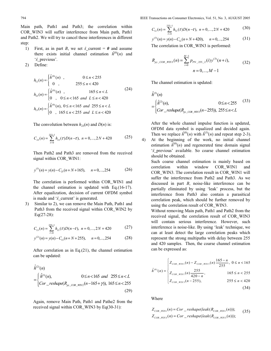
TCCR is shown in Fig.6.
In Fig.6, G1 and G2 represent two consecutive guard
intervals. is the estimated channel impulse response. We first
make linear convolution between guard interval and . The
convolution result G has the length of 420+L-1, we then
perform calculations as:
(36)
1
2
m
−
=
m
m
420)
X ( ) Frame body( ) G(
, =
=
m
m
m
X ( ) G2( ) G( )
0 ≤ < −
n
n L
1
X ( ) X ( ),
=
1
− ≤ <
n N
n
Frame body( ),
−
m
+
n
n
X( )
0,...,
L
−
2
2
+
L
1
X(n) is the OFDM data symbol after TCCR. Then the one-
tap frequency equalization can be used:
S
ˆ
h
FFT(X)/ FFT( )
=
S is the equalized data symbol in frequency domain.
Since there is only ±1 in PN guard interval, the linear
convolution and processes in Eq.(36) only involve addition
and subtraction calculations. So TCCR can be easily
implemented.
(37)
V. SIMULATION RESULTS
Computational simulation is performed to verify above
channel estimation and equalization algorithms. We will
compare the performance between DMB-T system and DVB-T
system under wireless frequency selective environment. Some
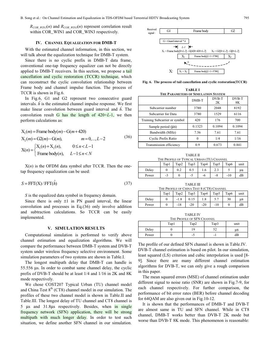
simulation parameters of two systems are shown in Table.I.
The longest multipath delay that DMB-T can handle is
55.556 μs. In order to combat same channel delay, the cyclic
prefix of DVB-T should be at least 1/4 and 1/16 in 2K and 8K
mode respectively.
We chose COST207 Typical Urban (TU) channel model
and China Test 8th (CT8) channel model in our simulation. The
profiles of these two channel model is shown in Table.II and
Table.III. The longest delay of TU channel and CT8 channel is
5 μs and 31.8μs respectively. Besides, when in single
frequency network (SFN) application, there will be strong
multipath with much longer delay. In order to test such
situation, we define another SFN channel in our simulation.
G = Guard interval * h
L-1
X1 = Frame body[0~L-2] - G[420~420+L-2]
X2 = G2[0~L-2] - G[0~L-2]
X1
Frame body[L+1~3780]
X2
+
X:
X1 + X2
Frame body[L+1~3780]
Fig. 6. The process of tail cancellation and cyclic restoration(TCCR)
THE PARAMETERS OF SIMULATION SYSTEM
TABLE I
Subcarrier number
Subcarrier for Data
Training Subcarrier or symbol
Sample period (μs)
Bandwidth (MHz)
Cyclic Prefix Ratio
Transmission efficiency
DMB-T
3780
3780
420
DVB-T
DVB-T
2K
2048
1529
176
8K
8192
6116
700
0.1323
0.1094
0.1094
7.56
0
0.9
7.61
1/4
0.673
7.61
1/16
0.841
Delay
Power
Delay
Power
Delay
Power
TABLE II
THE PROFILE OF TYPICAL URBAN (TU) CHANNEL
Tap1 Tap2 Tap3 Tap4 Tap5 Tap6
0
-3
0.2
0
0.5
-5
TABLE III
1.6
-6
2.3
-8
5
-10
THE PROFILE OF CHINA TEST 8 (CT8) CHANNEL
Tap1 Tap2 Tap3 Tap4 Tap5 Tap6
30
0
0.15
-20
-1.8
-18
1.8
-20
5.7
-10
0
0
unit
μs
dB
unit
μs
dB
TABLE IV
THE PROFILE OF SFN CHANNEL
Tap1
0
0
Tap2
19
-5
Tap3
52
-1
unit
μs
dB
The profile of our defined SFN channel is shown in Table.IV.
DVB-T channel estimation is based on pilot. In our simulation,
least squared (LS) criterion and cubic interpolation is used [8-
9]. Since
there are many different channel estimation
algorithms for DVB-T, we can only give a rough comparison
in this paper.
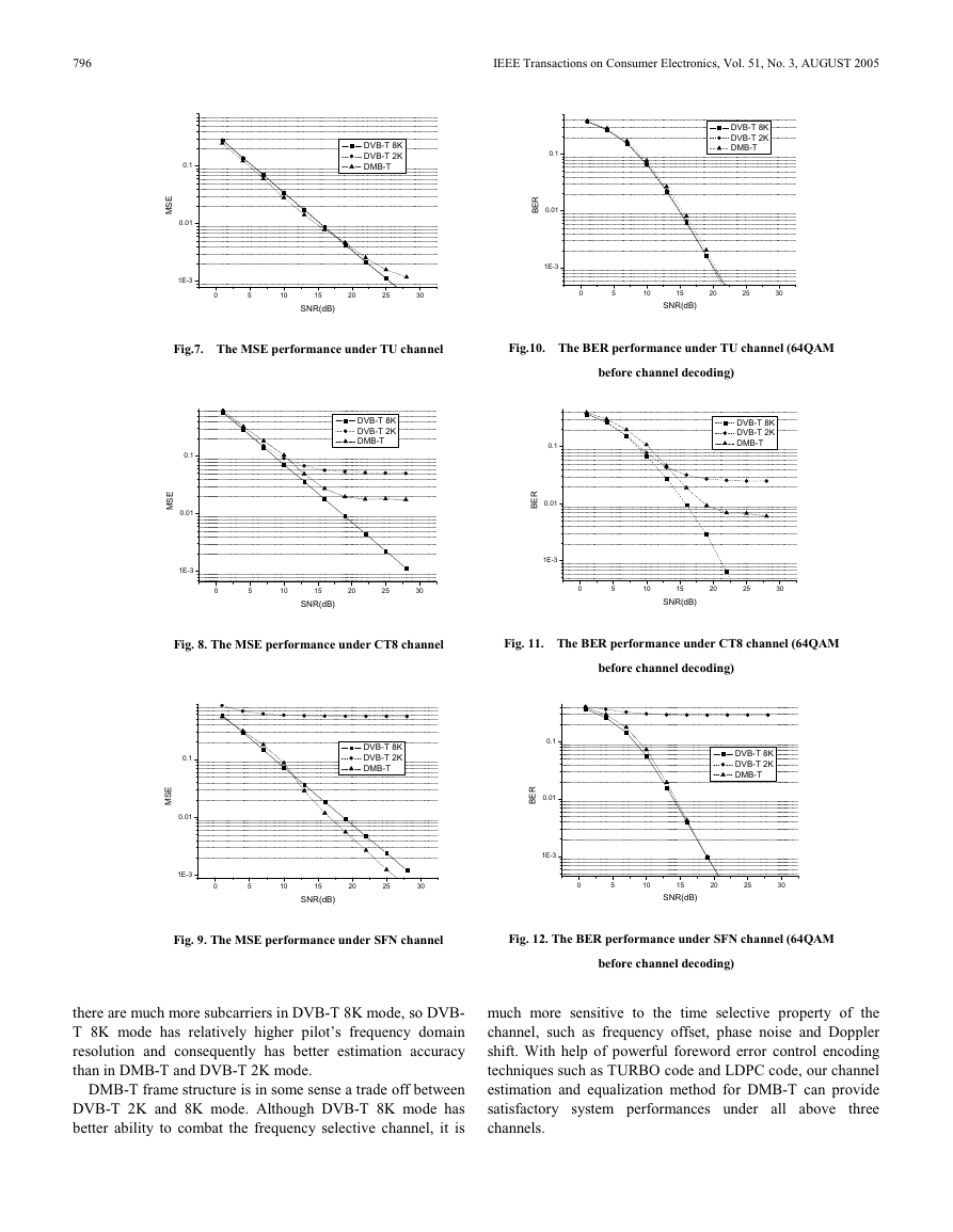
The mean squared errors (MSE) of channel estimation under
different signal to noise ratio (SNR) are shown in Fig.7-9, for
each channel respectively. For further comparison,
the
performance of bit error rates (BER) before channel decoding
for 64QAM are also given out in Fig.10-12.
It is shown that the performances of DMB-T and DVB-T
are almost same in TU and SFN channel. While in CT8
channel, DMB-T works better than DVB-T 2K mode but
worse than DVB-T 8K mode. This phenomenon is reasonable:
�
796
IEEE Transactions on Consumer Electronics, Vol. 51, No. 3, AUGUST 2005
0.1
E
S
M
0.01
1E-3
DVB-T 8K
DVB-T 2K
DMB-T
0.1
R
E
B
0.01
1E-3
DVB-T 8K
DVB-T 2K
DMB-T
0
5
10
15
20
25
30
SNR(dB)
0
5
10
15
20
25
30
SNR(dB)
Fig.7. The MSE performance under TU channel
DVB-T 8K
DVB-T 2K
DMB-T
0.1
E
S
M
0.01
1E-3
0
5
10
15
20
25
30
SNR(dB)
Fig.10. The BER performance under TU channel (64QAM
before channel decoding)
DVB-T 8K
DVB-T 2K
DMB-T
0.1
R
E
B
0.01
1E-3
0
5
10
15
20
25
30
SNR(dB)
Fig. 8. The MSE performance under CT8 channel
Fig. 11. The BER performance under CT8 channel (64QAM
before channel decoding)
0.1
E
S
M
0.01
1E-3
DVB-T 8K
DVB-T 2K
DMB-T
0.1
R
E
B
0.01
1E-3
DVB-T 8K
DVB-T 2K
DMB-T
0
5
10
15
20
25
30
0
5
10
15
20
25
30
SNR(dB)
SNR(dB)
Fig. 9. The MSE performance under SFN channel
Fig. 12. The BER performance under SFN channel (64QAM
before channel decoding)
there are much more subcarriers in DVB-T 8K mode, so DVB-
T 8K mode has relatively higher pilot’s frequency domain
resolution and consequently has better estimation accuracy
than in DMB-T and DVB-T 2K mode.
DMB-T frame structure is in some sense a trade off between
DVB-T 2K and 8K mode. Although DVB-T 8K mode has
better ability to combat the frequency selective channel, it is
much more sensitive to the time selective property of the
channel, such as frequency offset, phase noise and Doppler
shift. With help of powerful foreword error control encoding
techniques such as TURBO code and LDPC code, our channel
estimation and equalization method for DMB-T can provide
satisfactory system performances under all above
three
channels.
�
B. Song et al.: On Channel Estimation and Equalization in TDS-OFDM based Terrestrial HDTV Broadcasting System
797
VI. CONCLUSION
In This paper, we propose a channel estimation and
equalization method for DMB-T, a TDS-OFDM based
terrestrial HDTV broadcasting system. Our proposed channel
estimation algorithm is based on time domain correlation and
iterative interference cancellation techniques. In order to
equalize the channel with simple one-tap frequency domain
equalizer, a tail cancellation and cyclic restoration (TCCR)
technique is used. Simulation results show that such method
can provide satisfactory performance for DMB-T system.
REFERENCES
[1] J. Wang; Z.X. Yang; C.Y. Pan; M. Han; L. Yang, “A combined code
acquisition and symbol timing recovery method for TDS-OFDM,” IEEE
Trans. Broadcasting, Vol. 49, pp. 304-308, Sept. 2003.
[2] D. Huang; L. Yang; H. Xing; Z. Zhou, “Multiplexing guard intervals
and time domain pilots in OFDM systems”, Consumer Electronics,
2001. ICCE. International Conference on, pp. 68-69, June 2001.
[3] Z.X. Yang; L. Tong; L. Yang, “Outage probability comparison of CP-
OFDM and TDS-OFDM for broadcast channels”, IEEE Global
Telecommunications Conference, 2002. GLOBECOM '02., Vol. 1, pp.
594-598, Nov. 2002.
[4] Z.W. Zheng; Z.X. Yang; C.Y. Pan; Y.S. Zhu, “Robust phase noise
suppression scheme for TDS-OFDM-based digital television terrestrial
broadcasting systems”, IEEE Trans. Consumer Electronics, Vol. 50, pp.
436-442, May. 2004.
[5] Z.W. Zheng; Z.X. Yang; C. Y. Pan; Y.S. Zhu, “Synchronization and
channel estimation for TDS-OFDM systems”, IEEE 58th Vehicular
Technology Conference. VTC 2003-Fall, Vol. 2, pp. 1229-1233, Oct.
2003.
[6] “Terrestrial Digital Multimedia/Television Broadcasting System,” P.R.
China Patent 00 123 597.4 filed Aug.25, 2000, issued Mar. 21,2001.
[7] ETSI, “Digital Video Broadcasting: Framing Structure, Channel coding,
for Digital Terrestrial Television,” European
and Modulation
Telecommunication Standard EN300744, Aug. 1997.
[8] S. Coleri, M. Ergen, A. Puri and A. Bahai, “Channel Estimation
Techniques Based on Pilot Arrangement in OFDM Systems,” IEEE
Trans. Broadcasting, Vol.48, No. 3, September 2002.
[9] M.H. Hsieh and C.H. Wei, “Channel Estimation for OFDM systems
Based on Comb-Type Pilot Arrangement in Frequency selective Fading
Channels,” IEEE Trans. Consumer Electronics, vol. 44, no. 1, Feb.
1998
Bowei Song received the B.Sc. and M. Sc. degrees
from AnHui University, HeFei, China, in 1999 and
NanJing University of Aeronautics and Astronautics,
NanJing, China, in 2003 respectively. Now he is
studying for Ph.D. degree in Shanghai Jiao Tong
University. His research interests include HDTV and
wireless communications.
Lin Gui received the Ph.D degree at ZheJiang
University in 2002. Since 2002, she worked in the
Insititute of Wireless Communication Technology of
ShangHai JiaoTong University. Her primary research
work and interests are in the areas of compensating
channel fading.
Yunfeng Guan received the B.Sc. and Ph.D. degree from the Department of
Electronics and Information Technology in ZheJiang University,Hangzhou,
China, in 1998 and 2003 respectively. His research interests include HDTV
and wireless communications.
Wenjun Zhang received
the Ph.D. degree from
Shanghai Jiao Tong University, Shanghai,China, in
1989. From 1990 to 1993, he had been working as a
postdoctoral researcher at Philips Communications
Industry Co. As professor and vice president, he is now
with Shanghai Jiao Tong University. His research
interests include HDTV, image communications and
wireless communications.
�




 2023年江西萍乡中考道德与法治真题及答案.doc
 2012年重庆南川中考生物真题及答案.doc
 2013年江西师范大学地理学综合及文艺理论基础考研真题.doc
 2020年四川甘孜小升初语文真题及答案I卷.doc
 2020年注册岩土工程师专业基础考试真题及答案.doc
 2023-2024学年福建省厦门市九年级上学期数学月考试题及答案.doc
 2021-2022学年辽宁省沈阳市大东区九年级上学期语文期末试题及答案.doc
 2022-2023学年北京东城区初三第一学期物理期末试卷及答案.doc
 2018上半年江西教师资格初中地理学科知识与教学能力真题及答案.doc
 2012年河北国家公务员申论考试真题及答案-省级.doc
 2020-2021学年江苏省扬州市江都区邵樊片九年级上学期数学第一次质量检测试题及答案.doc
 2022下半年黑龙江教师资格证中学综合素质真题及答案.doc