logo资料库

STM32L151xx,STM32L152xx和STM32L162xx的Flash和EEPROM的编程手册.pdf

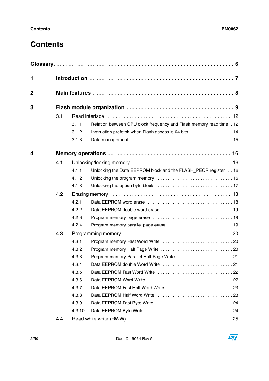
第1页 / 共50页
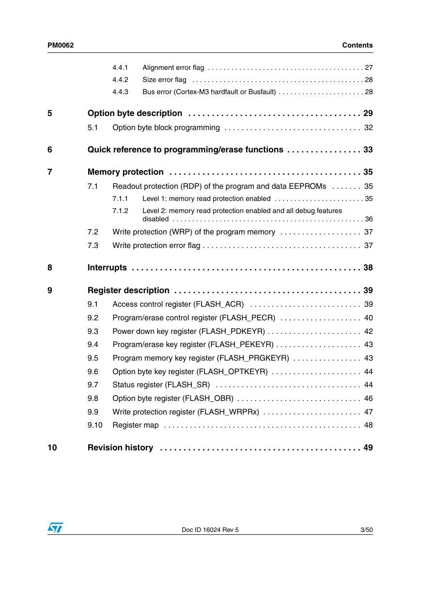
第2页 / 共50页
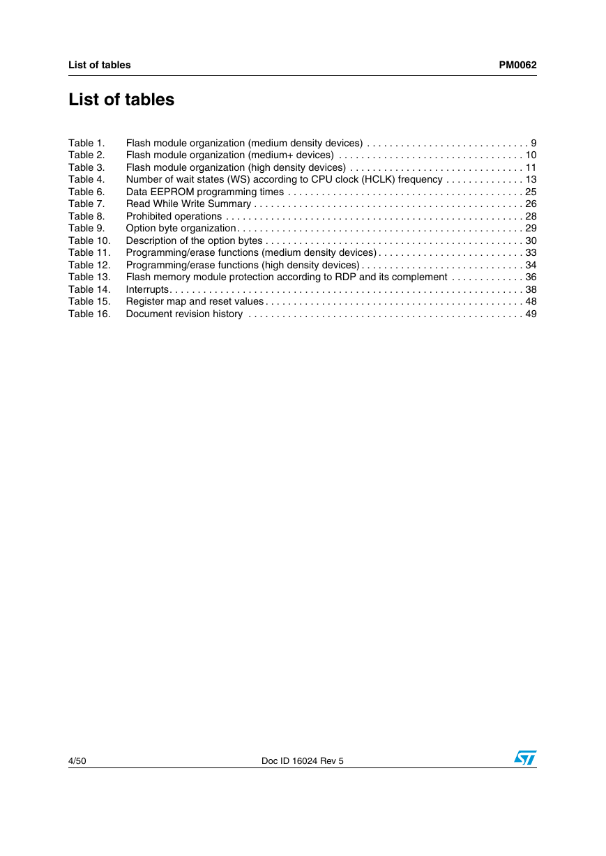
第3页 / 共50页
第4页 / 共50页
第5页 / 共50页
第6页 / 共50页
第7页 / 共50页
第8页 / 共50页
资料共50页,剩余部分请下载后查看
Figure 1. Flash memory programming overview
Glossary
1 Introduction
2 Main features
3 Flash module organization
Table 1. Flash module organization (medium density devices)
Table 2. Flash module organization (medium+ devices)
Table 3. Flash module organization (high density devices)
3.1 Read interface
3.1.1 Relation between CPU clock frequency and Flash memory read time
Table 4. Number of wait states (WS) according to CPU clock (HCLK) frequency
3.1.2 Instruction prefetch when Flash access is 64 bits
Figure 2. Sequential 32 bits instructions execution
3.1.3 Data management
4 Memory operations
4.1 Unlocking/locking memory
4.1.1 Unlocking the Data EEPROM block and the FLASH_PECR register
4.1.2 Unlocking the program memory
4.1.3 Unlocking the option byte block
4.2 Erasing memory
4.2.1 Data EEPROM word erase
4.2.2 Data EEPROM double word erase
4.2.3 Program memory page erase
4.2.4 Program memory parallel page erase
4.3 Programming memory
4.3.1 Program memory Fast Word Write
4.3.2 Program memory Half Page Write
4.3.3 Program memory Parallel Half Page Write
4.3.4 Data EEPROM double Word Write
4.3.5 Data EEPROM Fast Word Write
4.3.6 Data EEPROM Word Write
4.3.7 Data EEPROM Fast Half Word Write
4.3.8 Data EEPROM Half Word Write
4.3.9 Data EEPROM Fast Byte Write
4.3.10 Data EEPROM Byte Write
Table 6. Data EEPROM programming times
4.4 Read while write (RWW)
Table 7. Read While Write Summary
4.4.1 Alignment error flag
4.4.2 Size error flag
Table 8. Prohibited operations
4.4.3 Bus error (Cortex-M3 hardfault or Busfault)
5 Option byte description
Table 9. Option byte organization
Table 10. Description of the option bytes
5.1 Option byte block programming
6 Quick reference to programming/erase functions
Table 11. Programming/erase functions (medium density devices)
Table 12. Programming/erase functions (high density devices)
7 Memory protection
7.1 Readout protection (RDP) of the program and data EEPROMs
7.1.1 Level 1: memory read protection enabled
7.1.2 Level 2: memory read protection enabled and all debug features disabled
Figure 3. RDP levels
Table 13. Flash memory module protection according to RDP and its complement
7.2 Write protection (WRP) of the program memory
7.3 Write protection error flag
8 Interrupts
Table 14. Interrupts
9 Register description
9.1 Access control register (FLASH_ACR)
Note: 32-bit access is a low power mode. It is used only at low frequencies, that is with 0 wait state of latency and prefetch off.
Note: This bit cannot be written at the same time as the LATENCY and PRFTEN bits.
Note: Prefetch can be enabled only when ACC64 is set. This bit can be set or cleared only if ACC64 is set.
Note: Latency can be set only when ACC64 is set. This bit can be set or cleared only if ACC64 is set.
9.2 Program/erase control register (FLASH_PECR)
Note: This bit is available in high density devices only.
9.3 Power down key register (FLASH_PDKEYR)
9.4 Program/erase key register (FLASH_PEKEYR)
9.5 Program memory key register (FLASH_PRGKEYR)
9.6 Option byte key register (FLASH_OPTKEYR)
9.7 Status register (FLASH_SR)
Note: This bit is available in high density devices only.
9.8 Option byte register (FLASH_OBR)
Note: This bit is available in high density devices only.
Note: If the BOR is disabled, a “grey zone” exists between 1.65 V and the VPDR threshold (this means that VDD33 may be below the minimum operating voltage (1.65 V) without causing a reset until it crosses the VPDR threshold)
9.9 Write protection register (FLASH_WRPRx)
Note: FLASH_WRP2 is available in medium+ and high density devices
FLASH_WRP3 is available in high density devices only.
9.10 Register map
Table 15. Register map and reset values
10 Revision history
Table 16. Document revision history
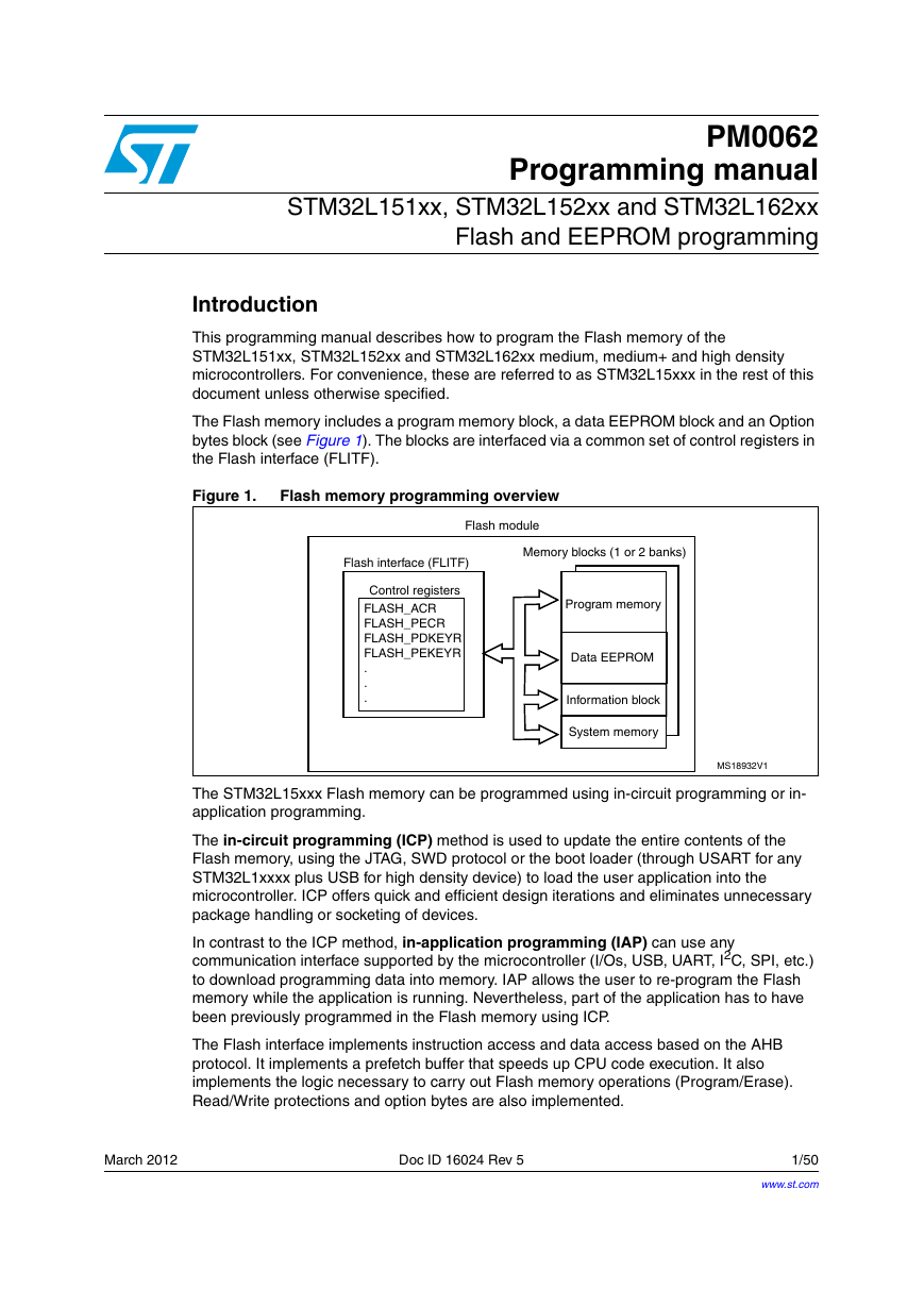
PM0062 Programming manual STM32L151xx, STM32L152xx and STM32L162xx Flash and EEPROM programming Introduction This programming manual describes how to program the Flash memory of the STM32L151xx, STM32L152xx and STM32L162xx medium, medium+ and high density microcontrollers. For convenience, these are referred to as STM32L15xxx in the rest of this document unless otherwise specified. The Flash memory includes a program memory block, a data EEPROM block and an Option bytes block (see Figure 1). The blocks are interfaced via a common set of control registers in the Flash interface (FLITF). Figure 1. Flash memory programming overview The STM32L15xxx Flash memory can be programmed using in-circuit programming or in- application programming. The in-circuit programming (ICP) method is used to update the entire contents of the Flash memory, using the JTAG, SWD protocol or the boot loader (through USART for any STM32L1xxxx plus USB for high density device) to load the user application into the microcontroller. ICP offers quick and efficient design iterations and eliminates unnecessary package handling or socketing of devices. In contrast to the ICP method, in-application programming (IAP) can use any communication interface supported by the microcontroller (I/Os, USB, UART, I2C, SPI, etc.) to download programming data into memory. IAP allows the user to re-program the Flash memory while the application is running. Nevertheless, part of the application has to have been previously programmed in the Flash memory using ICP. The Flash interface implements instruction access and data access based on the AHB protocol. It implements a prefetch buffer that speeds up CPU code execution. It also implements the logic necessary to carry out Flash memory operations (Program/Erase). Read/Write protections and option bytes are also implemented. March 2012 Doc ID 16024 Rev 5 1/50 www.st.com
Contents Contents PM0062 Glossary. . . . . . . . . . . . . . . . . . . . . . . . . . . . . . . . . . . . . . . . . . . . . . . . . . . . . . . . . . . . 6 1 2 3 4 Introduction . . . . . . . . . . . . . . . . . . . . . . . . . . . . . . . . . . . . . . . . . . . . . . . . 7 Main features . . . . . . . . . . . . . . . . . . . . . . . . . . . . . . . . . . . . . . . . . . . . . . . 8 Flash module organization . . . . . . . . . . . . . . . . . . . . . . . . . . . . . . . . . . . . 9 Read interface . . . . . . . . . . . . . . . . . . . . . . . . . . . . . . . . . . . . . . . . . . . . . 12 3.1 3.1.1 Relation between CPU clock frequency and Flash memory read time . 12 Instruction prefetch when Flash access is 64 bits . . . . . . . . . . . . . . . . . 14 3.1.2 3.1.3 Data management . . . . . . . . . . . . . . . . . . . . . . . . . . . . . . . . . . . . . . . . . 15 4.3 Memory operations . . . . . . . . . . . . . . . . . . . . . . . . . . . . . . . . . . . . . . . . . 16 Unlocking/locking memory . . . . . . . . . . . . . . . . . . . . . . . . . . . . . . . . . . . . 16 4.1 4.1.1 Unlocking the Data EEPROM block and the FLASH_PECR register . . 16 Unlocking the program memory . . . . . . . . . . . . . . . . . . . . . . . . . . . . . . . 16 4.1.2 4.1.3 Unlocking the option byte block . . . . . . . . . . . . . . . . . . . . . . . . . . . . . . . 17 Erasing memory . . . . . . . . . . . . . . . . . . . . . . . . . . . . . . . . . . . . . . . . . . . . 18 Data EEPROM word erase . . . . . . . . . . . . . . . . . . . . . . . . . . . . . . . . . . 18 4.2.1 Data EEPROM double word erase . . . . . . . . . . . . . . . . . . . . . . . . . . . . 19 4.2.2 4.2.3 Program memory page erase . . . . . . . . . . . . . . . . . . . . . . . . . . . . . . . . 19 4.2.4 Program memory parallel page erase . . . . . . . . . . . . . . . . . . . . . . . . . . 19 Programming memory . . . . . . . . . . . . . . . . . . . . . . . . . . . . . . . . . . . . . . . 20 4.3.1 Program memory Fast Word Write . . . . . . . . . . . . . . . . . . . . . . . . . . . . 20 Program memory Half Page Write . . . . . . . . . . . . . . . . . . . . . . . . . . . . . 20 4.3.2 Program memory Parallel Half Page Write . . . . . . . . . . . . . . . . . . . . . . 21 4.3.3 4.3.4 Data EEPROM double Word Write . . . . . . . . . . . . . . . . . . . . . . . . . . . . 21 Data EEPROM Fast Word Write . . . . . . . . . . . . . . . . . . . . . . . . . . . . . . 22 4.3.5 Data EEPROM Word Write . . . . . . . . . . . . . . . . . . . . . . . . . . . . . . . . . . 22 4.3.6 4.3.7 Data EEPROM Fast Half Word Write . . . . . . . . . . . . . . . . . . . . . . . . . . . 23 Data EEPROM Half Word Write . . . . . . . . . . . . . . . . . . . . . . . . . . . . . . 23 4.3.8 4.3.9 Data EEPROM Fast Byte Write . . . . . . . . . . . . . . . . . . . . . . . . . . . . . . . 24 4.3.10 Data EEPROM Byte Write . . . . . . . . . . . . . . . . . . . . . . . . . . . . . . . . . . . 24 Read while write (RWW) . . . . . . . . . . . . . . . . . . . . . . . . . . . . . . . . . . . . . 25 4.2 4.4 2/50 Doc ID 16024 Rev 5
PM0062 Contents 5 6 7 8 9 4.4.1 4.4.2 4.4.3 Alignment error flag . . . . . . . . . . . . . . . . . . . . . . . . . . . . . . . . . . . . . . . . 27 Size error flag . . . . . . . . . . . . . . . . . . . . . . . . . . . . . . . . . . . . . . . . . . . . 28 Bus error (Cortex-M3 hardfault or Busfault) . . . . . . . . . . . . . . . . . . . . . . 28 Option byte description . . . . . . . . . . . . . . . . . . . . . . . . . . . . . . . . . . . . . 29 Option byte block programming . . . . . . . . . . . . . . . . . . . . . . . . . . . . . . . . 32 5.1 Quick reference to programming/erase functions . . . . . . . . . . . . . . . . 33 Memory protection . . . . . . . . . . . . . . . . . . . . . . . . . . . . . . . . . . . . . . . . . 35 Readout protection (RDP) of the program and data EEPROMs . . . . . . . 35 7.1 7.1.1 Level 1: memory read protection enabled . . . . . . . . . . . . . . . . . . . . . . . 35 Level 2: memory read protection enabled and all debug features 7.1.2 disabled . . . . . . . . . . . . . . . . . . . . . . . . . . . . . . . . . . . . . . . . . . . . . . . . . 36 7.2 Write protection (WRP) of the program memory . . . . . . . . . . . . . . . . . . . 37 7.3 Write protection error flag . . . . . . . . . . . . . . . . . . . . . . . . . . . . . . . . . . . . . 37 Interrupts . . . . . . . . . . . . . . . . . . . . . . . . . . . . . . . . . . . . . . . . . . . . . . . . . 38 Register description . . . . . . . . . . . . . . . . . . . . . . . . . . . . . . . . . . . . . . . . 39 Access control register (FLASH_ACR) . . . . . . . . . . . . . . . . . . . . . . . . . . 39 9.1 Program/erase control register (FLASH_PECR) . . . . . . . . . . . . . . . . . . . 40 9.2 9.3 Power down key register (FLASH_PDKEYR) . . . . . . . . . . . . . . . . . . . . . . 42 Program/erase key register (FLASH_PEKEYR) . . . . . . . . . . . . . . . . . . . . 43 9.4 Program memory key register (FLASH_PRGKEYR) . . . . . . . . . . . . . . . . 43 9.5 9.6 Option byte key register (FLASH_OPTKEYR) . . . . . . . . . . . . . . . . . . . . . 44 Status register (FLASH_SR) . . . . . . . . . . . . . . . . . . . . . . . . . . . . . . . . . . 44 9.7 9.8 Option byte register (FLASH_OBR) . . . . . . . . . . . . . . . . . . . . . . . . . . . . . 46 9.9 Write protection register (FLASH_WRPRx) . . . . . . . . . . . . . . . . . . . . . . . 47 9.10 Register map . . . . . . . . . . . . . . . . . . . . . . . . . . . . . . . . . . . . . . . . . . . . . . 48 10 Revision history . . . . . . . . . . . . . . . . . . . . . . . . . . . . . . . . . . . . . . . . . . . 49 Doc ID 16024 Rev 5 3/50
List of tables List of tables PM0062 Table 1. Table 2. Table 3. Table 4. Table 6. Table 7. Table 8. Table 9. Table 10. Table 11. Table 12. Table 13. Table 14. Table 15. Table 16. Flash module organization (medium density devices) . . . . . . . . . . . . . . . . . . . . . . . . . . . . . 9 Flash module organization (medium+ devices) . . . . . . . . . . . . . . . . . . . . . . . . . . . . . . . . . 10 Flash module organization (high density devices) . . . . . . . . . . . . . . . . . . . . . . . . . . . . . . . 11 Number of wait states (WS) according to CPU clock (HCLK) frequency . . . . . . . . . . . . . . 13 Data EEPROM programming times . . . . . . . . . . . . . . . . . . . . . . . . . . . . . . . . . . . . . . . . . . 25 Read While Write Summary . . . . . . . . . . . . . . . . . . . . . . . . . . . . . . . . . . . . . . . . . . . . . . . . 26 Prohibited operations . . . . . . . . . . . . . . . . . . . . . . . . . . . . . . . . . . . . . . . . . . . . . . . . . . . . . 28 Option byte organization. . . . . . . . . . . . . . . . . . . . . . . . . . . . . . . . . . . . . . . . . . . . . . . . . . . 29 Description of the option bytes . . . . . . . . . . . . . . . . . . . . . . . . . . . . . . . . . . . . . . . . . . . . . . 30 Programming/erase functions (medium density devices) . . . . . . . . . . . . . . . . . . . . . . . . . . 33 Programming/erase functions (high density devices) . . . . . . . . . . . . . . . . . . . . . . . . . . . . . 34 Flash memory module protection according to RDP and its complement . . . . . . . . . . . . . 36 Interrupts. . . . . . . . . . . . . . . . . . . . . . . . . . . . . . . . . . . . . . . . . . . . . . . . . . . . . . . . . . . . . . . 38 Register map and reset values . . . . . . . . . . . . . . . . . . . . . . . . . . . . . . . . . . . . . . . . . . . . . . 48 Document revision history . . . . . . . . . . . . . . . . . . . . . . . . . . . . . . . . . . . . . . . . . . . . . . . . . 49 4/50 Doc ID 16024 Rev 5
PM0062 List of figures List of figures Figure 1. Figure 2. Figure 3. Flash memory programming overview . . . . . . . . . . . . . . . . . . . . . . . . . . . . . . . . . . . . . . . . . 1 Sequential 32 bits instructions execution . . . . . . . . . . . . . . . . . . . . . . . . . . . . . . . . . . . . . . 14 RDP levels . . . . . . . . . . . . . . . . . . . . . . . . . . . . . . . . . . . . . . . . . . . . . . . . . . . . . . . . . . . . . 36 Doc ID 16024 Rev 5 5/50
Glossary Glossary PM0062 This section gives a brief definition of acronyms and abbreviations used in this document: ● Medium-density devices are STM32L151xx and STM32L152xx microcontrollers where the program memory density ranges between 64 and 128 Kbytes. ● Medium+ density devices are STM32L151xx, STM32L152xx and STM32L162xx microcontrollers where the program memory density size is 256 Kbytes. Note: For CSP64, BGA132, QFP144 packages, the chip follows the characteristics of high density devices with bank 1 containing 192 Kbytes of program flash and 6 Kbytes of data EEPROM and with bank 2 containing 64 Kbytes of program flash and 2 Kbytes of data EEPROM. ● High-density devices are STM32L151xx, STM32L152xx and STM32L162xx microcontrollers where the program memory density is 384 Kbytes. The Cortex-M3 core integrates two debug ports: – JTAG debug port (JTAG-DP) provides a 5-pin standard interface based on the Joint Test Action Group (JTAG) protocol SWD debug port (SWD-DP) provides a 2-pin (clock and data) interface based on the Serial Wire Debug (SWD) protocol For both the JTAG and SWD protocols please refer to the ARM CoreSight on-chip trace and debug documentation ● Word: data/instruction of 32-bit length ● Half word: data/instruction of 16-bit length Byte: data of 8-bit length Double word: data of 64-bit length Page: 64 words of program memory Sector: 16 pages (write protection granularity) IAP (in-application programming): IAP is the ability to re-program the Flash memory of a microcontroller while the user program is running. ICP (in-circuit programming): ICP is the ability to program the Flash memory of a microcontroller using the JTAG protocol, the SWD protocol or the boot loader while the device is mounted on the user application board. I-Code: this bus connects the Instruction bus of the Cortex-M3 core to the Flash instruction interface. Prefetch is performed on this bus. D-Code: this bus connects the D-Code bus (literal load and debug access) of the Cortex-M3 to the Flash Data Interface. – ● ● ● ● ● ● ● ● ● ● Option bytes: product configuration bits stored in Flash memory ● OBL: option byte loader ● AHB: advanced high-performance bus CPU (central processing unit): this term stands for the Cortex-M3 core ● 6/50 Doc ID 16024 Rev 5
PM0062 1 Introduction Introduction The Flash memory interface manages CPU AHB I-Code and D-Code accesses to the memory module. It implements the erase and program memory operations and the read and write protection mechanisms. The Flash memory interface accelerates code execution with a system of instruction prefetch. Doc ID 16024 Rev 5 7/50
Main features 2 Main features Up to 396 Kbytes total storage capacity ● ● Memory organization: PM0062 Up to 384 Kbytes of program memory Up to 12 Kbytes of data EEPROM Up to 8 Kbytes of system memory and 64 bytes of option bytes – – – Dual bank organisation (in high density devices): each bank has up to: – – 192 Kbytes of program memory and 6 Kbytes of data EEPROM 4 Kbytes of system memory and 32 bytes of option bytes ● Flash memory interface (FLITF) features: ● ● Flash module read operations: read access is performed on 64 or 32 bits Flash module program/erase operations Read/write protection ● ● Write access is performed on 32 bits ● Option byte loader Low power mode: ● – Flash module in Power down mode when the STM32L15xxx is in Standby mode or Stop mode Flash module can be placed in Power down or Idle mode when the STM32L15xxx is in Sleep mode Flash module can be placed in Power down or Idle mode when the STM32L15xxx is in Run mode – – Note: The DMA can only access Flash memory module with read operations. 8/50 Doc ID 16024 Rev 5
分享到:
收藏