SSPPFFDD55441144DD
339966--cchhaannnneell 66--bbiitt SSoouurrccee DDrriivveerr wwiitthh
SSyysstteemm--oonn--cchhiipp ffoorr CCoolloorr
AAmmoorrpphhoouuss TTFFTT--LLCCDDss
PPrreelliimmiinnaarryy
JUL. 30, 2008
Version 0.5
ORISE Technology reserves the right to change this documentation without prior notice. Information provided by ORISE Technology is believed to be
accurate and reliable. However, ORISE Technology makes no warranty for any errors which may appear in this document. Contact ORISE Technology to
obtain the latest version of device specifications before placing your order. No responsibility is assumed by ORISE Technology for any infringement of patent
or other rights of third parties which may result from its use. In addition, ORISE Technology products are not authorized for use as critical components in life
support devices/ systems or aviation devices/systems, where a malfunction or failure of the product may reasonably be expected to result in significant injury to
the user, without the express written approval of ORISE Technology.
�
Preliminary
SPFD5414D
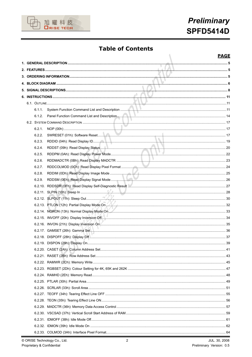
Table of Contents
PAGE
1. GENERAL DESCRIPTION .......................................................................................................................................................................... 5
2. FEATURES.................................................................................................................................................................................................. 5
3. ORDERING INFORMATION........................................................................................................................................................................ 5
4. BLOCK DIAGRAM ...................................................................................................................................................................................... 6
5. SIGNAL DESCRIPTIONS............................................................................................................................................................................ 8
6. INSTRUCTIONS........................................................................................................................................................................................ 11
6.1. OUTLINE...............................................................................................................................................................................................11
6.1.1. System Function Command List and Description .................................................................................................................11
6.1.2. Panel Function Command List and Description ................................................................................................................... 14
6.2. SYSTEM COMMAND DESCRIPTION ........................................................................................................................................................ 17
6.2.1. NOP (00h) ............................................................................................................................................................................ 17
6.2.2. SWRESET (01h): Software Reset........................................................................................................................................ 17
6.2.3. RDDID (04h): Read Display ID............................................................................................................................................. 19
6.2.4. RDDST (09h): Read Display Status ..................................................................................................................................... 20
6.2.5. RDDPM (0Ah): Read Display Power Mode.......................................................................................................................... 22
6.2.6. RDDMADCTR (0Bh): Read Display MADCTR .................................................................................................................... 23
6.2.7. RDDCOLMOD (0Ch): Read Display Pixel Format ............................................................................................................... 24
6.2.8. RDDIM (0Dh): Read Display Image Mode ........................................................................................................................... 25
6.2.9. RDDSM (0Eh): Read Display Signal Mode.......................................................................................................................... 26
6.2.10. RDDSDR (0Fh): Read Display Self-Diagnostic Result ........................................................................................................ 27
6.2.11. SLPIN (10h): Sleep In .......................................................................................................................................................... 28
6.2.12. SLPOUT (11h): Sleep Out.................................................................................................................................................... 30
6.2.13. PTLON (12h): Partial Display Mode On ............................................................................................................................... 32
6.2.14. NORON (13h): Normal Display Mode On ............................................................................................................................ 33
6.2.15. INVOFF (20h): Display Inversion Off.................................................................................................................................... 34
6.2.16. INVON (21h): Display Inversion On ..................................................................................................................................... 35
6.2.17. GAMSET (26h): Gamma Set................................................................................................................................................ 36
6.2.18. DISPOFF (28h): Display Off................................................................................................................................................. 37
6.2.19. DISPON (29h): Display On................................................................................................................................................... 39
6.2.20. CASET (2Ah): Column Address Set..................................................................................................................................... 41
6.2.21. RASET (2Bh): Row Address Set.......................................................................................................................................... 43
6.2.22. RAMWR (2Ch): Memory Write ............................................................................................................................................. 45
6.2.23. RGBSET (2Dh): Colour Setting for 4K, 65K and 262K ........................................................................................................ 47
6.2.24. RAMHD (2Eh): Memory Read.............................................................................................................................................. 48
6.2.25. PTLAR (30h): Partial Area.................................................................................................................................................... 49
6.2.26. SCRLAR (33h): Scroll Area.................................................................................................................................................. 51
6.2.27. TEOFF (34h): Tearing Effect Line OFF ................................................................................................................................ 55
6.2.28. TEON (35h): Tearing Effect Line ON.................................................................................................................................... 56
6.2.29. MADCTR (36h): Memory Data Access Control.................................................................................................................... 57
6.2.30. VSCSAD (37h): Vertical Scroll Start Address of RAM.......................................................................................................... 59
6.2.31. IDMOFF (38h): Idle Mode Off............................................................................................................................................... 61
6.2.32. IDMON (39h): Idle Mode On ................................................................................................................................................ 62
6.2.33. COLMOD (3Ah): Interface Pixel Format............................................................................................................................... 64
JUL. 30, 2008
Preliminary Version: 0.5
2
© ORISE Technology Co., Ltd.
Proprietary & Confidential
�
Preliminary
SPFD5414D
6.2.34. RDID1 (DAh): Read ID1 Value ............................................................................................................................................. 65
6.2.35. RDID2 (DBh): Read ID2 Value ............................................................................................................................................. 66
6.2.36. RDID3 (DCh): Read ID3 Value............................................................................................................................................. 67
6.3. PANEL COMMAND DESCRIPTION ........................................................................................................................................................... 68
6.3.1. FRMCTR1 (B1h): Frame Rate Control................................................................................................................................. 68
6.3.2.
INVCTR (B4h): Display Inversion Control ............................................................................................................................ 70
6.3.3. DISSET5 (B6h): Display Function set 5 ............................................................................................................................... 71
6.3.4. PWCTR1 (C0h): Power Control 1 ........................................................................................................................................ 73
6.3.5. PWCTR3 (C2h): Power Control 3 ........................................................................................................................................ 75
6.3.6. PWCTR2 (C3h): Power Control 2 ........................................................................................................................................ 76
6.3.7. PWCTR5 (C4h): Power Control 5 ........................................................................................................................................ 77
6.3.8. VMCTR1 (C5h): VCOM Control 1 ........................................................................................................................................ 78
6.3.9. VMCTR2 (C6h): VCOM Control 2 ........................................................................................................................................ 80
6.3.10. RDVMH (C8h): Read the VCOMH Value NV memory ......................................................................................................... 82
6.3.11. WRID2 (D1h): Write ID2 Value............................................................................................................................................. 83
6.3.12. WRID3 (D2h): Write ID3 Value............................................................................................................................................. 84
6.3.13. RDID4 (D3h): Read the ID4 value........................................................................................................................................ 85
6.3.14. NVFCTR1 (D9h): NV Memory Function Controller 1 ........................................................................................................... 86
6.3.15. NVFCTR2 (DEh): NV Memory Function Controller 2........................................................................................................... 89
6.3.16. NVFCTR3 (DFh): NV Memory Function Controller 3 ........................................................................................................... 90
6.3.17. GMCTRP1 (E0h): Gamma Correction Characteristics Setting ............................................................................................ 91
6.3.18. GMCTRN1 (E1h): Gamma Correction Characteristics Setting ............................................................................................ 93
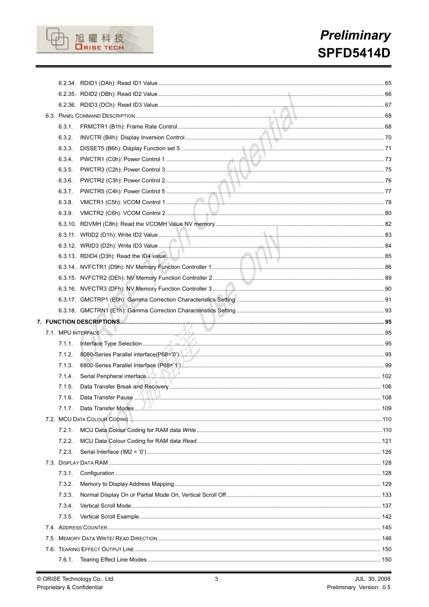
7. FUNCTION DESCRIPTIONS..................................................................................................................................................................... 95
7.1. MPU INTERFACE ................................................................................................................................................................................. 95
Interface Type Selection....................................................................................................................................................... 95
7.1.1.
7.1.2. 8080-Series Parallel interface(P68=’0’)................................................................................................................................ 95
7.1.3. 6800-Series Parallel Interface (P68=’1’) .............................................................................................................................. 99
7.1.4. Serial Peripheral interface.................................................................................................................................................. 102
7.1.5. Data Transfer Break and Recovery.................................................................................................................................... 106
7.1.6. Data Transfer Pause .......................................................................................................................................................... 108
7.1.7. Data Transfer Modes.......................................................................................................................................................... 109
7.2. MCU DATA COLOUR CODING ..............................................................................................................................................................110
7.2.1. MCU Data Colour Coding for RAM data Write ....................................................................................................................110
7.2.2. MCU Data Colour Coding for RAM data Read................................................................................................................... 121
7.2.3. Serial Interface (IM2 = ‘0’) .................................................................................................................................................. 126
7.3. DISPLAY DATA RAM .......................................................................................................................................................................... 128
7.3.1. Configuration...................................................................................................................................................................... 128
7.3.2. Memory to Display Address Mapping................................................................................................................................. 129
7.3.3. Normal Display On or Partial Mode On, Vertical Scroll Off ................................................................................................ 133
7.3.4. Vertical Scroll Mode............................................................................................................................................................ 137
7.3.5. Vertical Scroll Example....................................................................................................................................................... 142
7.4. ADDRESS COUNTER........................................................................................................................................................................... 145
7.5. MEMORY DATA WRITE/ READ DIRECTION ........................................................................................................................................... 146
7.6. TEARING EFFECT OUTPUT LINE.......................................................................................................................................................... 150
7.6.1. Tearing Effect Line Modes.................................................................................................................................................. 150
© ORISE Technology Co., Ltd.
Proprietary & Confidential
3
JUL. 30, 2008
Preliminary Version: 0.5
�
Preliminary
SPFD5414D
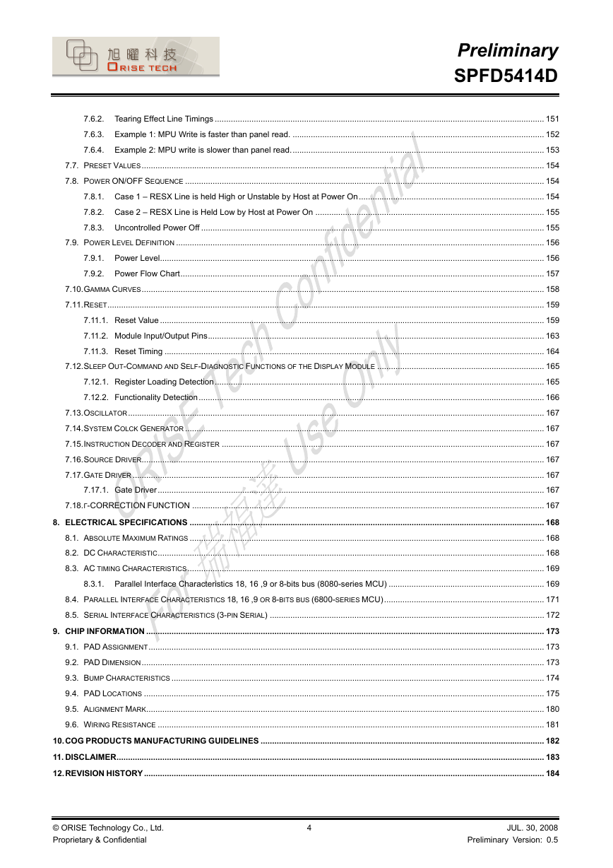
7.6.2. Tearing Effect Line Timings ................................................................................................................................................ 151
7.6.3. Example 1: MPU Write is faster than panel read. .............................................................................................................. 152
7.6.4. Example 2: MPU write is slower than panel read............................................................................................................... 153
7.7. PRESET VALUES................................................................................................................................................................................ 154
7.8. POWER ON/OFF SEQUENCE ............................................................................................................................................................. 154
7.8.1. Case 1 – RESX Line is held High or Unstable by Host at Power On................................................................................. 154
7.8.2. Case 2 – RESX Line is Held Low by Host at Power On .................................................................................................... 155
7.8.3. Uncontrolled Power Off ...................................................................................................................................................... 155
7.9. POWER LEVEL DEFINITION ................................................................................................................................................................. 156
7.9.1. Power Level........................................................................................................................................................................ 156
7.9.2. Power Flow Chart............................................................................................................................................................... 157
7.10. GAMMA CURVES................................................................................................................................................................................ 158
7.11. RESET............................................................................................................................................................................................... 159
7.11.1. Reset Value ........................................................................................................................................................................ 159
7.11.2. Module Input/Output Pins................................................................................................................................................... 163
7.11.3. Reset Timing ...................................................................................................................................................................... 164
7.12. SLEEP OUT-COMMAND AND SELF-DIAGNOSTIC FUNCTIONS OF THE DISPLAY MODULE ......................................................................... 165
7.12.1. Register Loading Detection................................................................................................................................................ 165
7.12.2. Functionality Detection....................................................................................................................................................... 166
7.13. OSCILLATOR...................................................................................................................................................................................... 167
7.14. SYSTEM COLCK GENERATOR ............................................................................................................................................................. 167
7.15. INSTRUCTION DECODER AND REGISTER ............................................................................................................................................. 167
7.16. SOURCE DRIVER................................................................................................................................................................................ 167
7.17. GATE DRIVER .................................................................................................................................................................................... 167
7.17.1. Gate Driver......................................................................................................................................................................... 167
7.18. Γ-CORRECTION FUNCTION .......................................................................................................................................................... 167
8. ELECTRICAL SPECIFICATIONS ........................................................................................................................................................... 168
8.1. ABSOLUTE MAXIMUM RATINGS ........................................................................................................................................................... 168
8.2. DC CHARACTERISTIC......................................................................................................................................................................... 168
8.3. AC TIMING CHARACTERISTICS............................................................................................................................................................ 169
8.3.1. Parallel Interface Characteristics 18, 16 ,9 or 8-bits bus (8080-series MCU) .................................................................... 169
8.4. PARALLEL INTERFACE CHARACTERISTICS 18, 16 ,9 OR 8-BITS BUS (6800-SERIES MCU)...................................................................... 171
8.5. SERIAL INTERFACE CHARACTERISTICS (3-PIN SERIAL) ........................................................................................................................ 172
9. CHIP INFORMATION .............................................................................................................................................................................. 173
9.1. PAD ASSIGNMENT............................................................................................................................................................................. 173
9.2. PAD DIMENSION................................................................................................................................................................................ 173
9.3. BUMP CHARACTERISTICS ................................................................................................................................................................... 174
9.4. PAD LOCATIONS ............................................................................................................................................................................... 175
9.5. ALIGNMENT MARK.............................................................................................................................................................................. 180
9.6. WIRING RESISTANCE ......................................................................................................................................................................... 181
10. COG PRODUCTS MANUFACTURING GUIDELINES ............................................................................................................................ 182
11. DISCLAIMER........................................................................................................................................................................................... 183
12. REVISION HISTORY............................................................................................................................................................................... 184
© ORISE Technology Co., Ltd.
Proprietary & Confidential
4
JUL. 30, 2008
Preliminary Version: 0.5
�
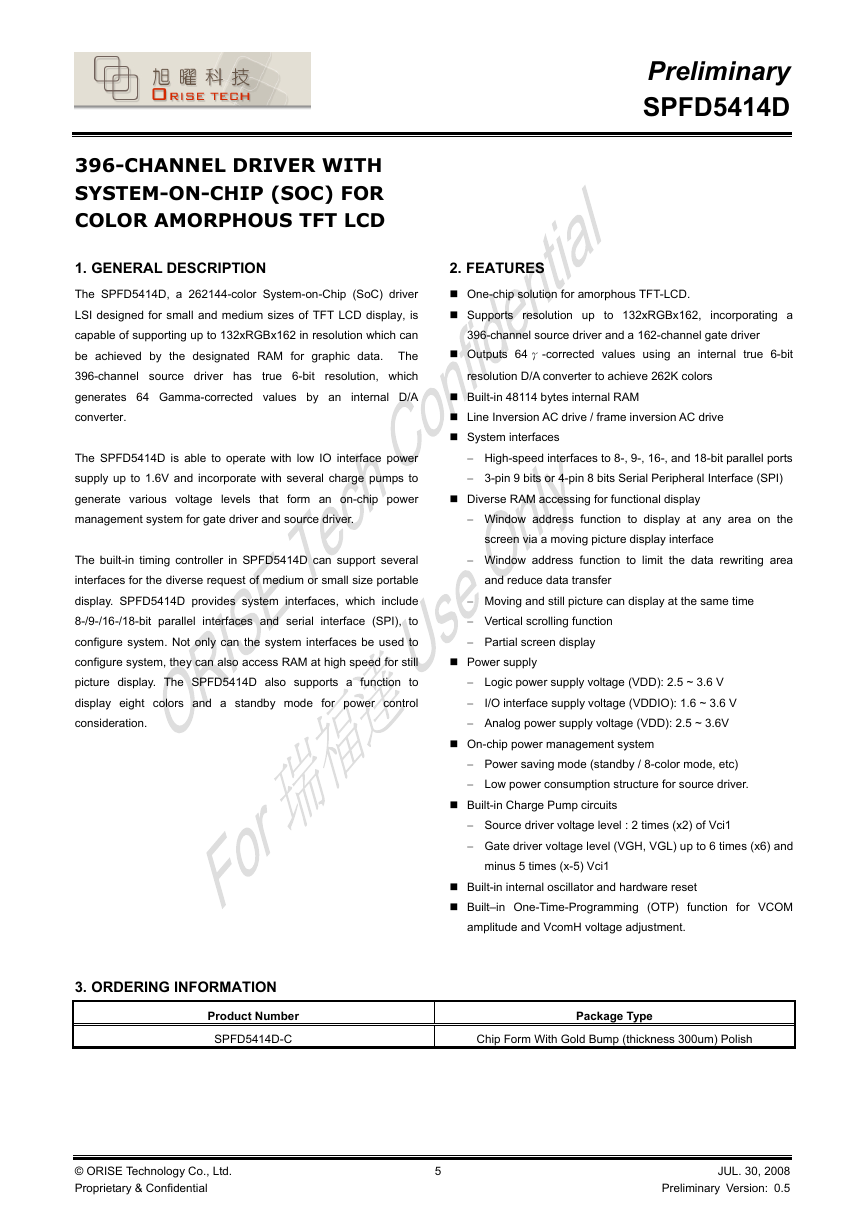
396-CHANNEL DRIVER WITH
SYSTEM-ON-CHIP (SOC) FOR
COLOR AMORPHOUS TFT LCD
1. GENERAL DESCRIPTION
The SPFD5414D, a 262144-color System-on-Chip (SoC) driver
LSI designed for small and medium sizes of TFT LCD display, is
capable of supporting up to 132xRGBx162 in resolution which can
be achieved by the designated RAM for graphic data. The
true 6-bit resolution, which
396-channel source driver has
generates 64 Gamma-corrected values by an
internal D/A
converter.
The SPFD5414D is able to operate with low IO interface power
supply up to 1.6V and incorporate with several charge pumps to
generate various voltage levels that form an on-chip power
management system for gate driver and source driver.
The built-in timing controller in SPFD5414D can support several
interfaces for the diverse request of medium or small size portable
display. SPFD5414D provides system interfaces, which include
8-/9-/16-/18-bit parallel interfaces and serial interface (SPI), to
configure system. Not only can the system interfaces be used to
configure system, they can also access RAM at high speed for still
picture display. The SPFD5414D also supports a function to
display eight colors and a standby mode for power control
consideration.
Preliminary
SPFD5414D
2. FEATURES
One-chip solution for amorphous TFT-LCD.
Supports resolution up to 132xRGBx162, incorporating a
396-channel source driver and a 162-channel gate driver
Outputs 64 γ-corrected values using an internal true 6-bit
resolution D/A converter to achieve 262K colors
Built-in 48114 bytes internal RAM
Line Inversion AC drive / frame inversion AC drive
System interfaces
− High-speed interfaces to 8-, 9-, 16-, and 18-bit parallel ports
− 3-pin 9 bits or 4-pin 8 bits Serial Peripheral Interface (SPI)
Diverse RAM accessing for functional display
− Window address function to display at any area on the
screen via a moving picture display interface
− Window address function to limit the data rewriting area
and reduce data transfer
− Moving and still picture can display at the same time
− Vertical scrolling function
− Partial screen display
Power supply
− Logic power supply voltage (VDD): 2.5 ~ 3.6 V
−
I/O interface supply voltage (VDDIO): 1.6 ~ 3.6 V
− Analog power supply voltage (VDD): 2.5 ~ 3.6V
On-chip power management system
− Power saving mode (standby / 8-color mode, etc)
− Low power consumption structure for source driver.
Built-in Charge Pump circuits
− Source driver voltage level : 2 times (x2) of Vci1
− Gate driver voltage level (VGH, VGL) up to 6 times (x6) and
minus 5 times (x-5) Vci1
Built-in internal oscillator and hardware reset
Built–in One-Time-Programming (OTP) function for VCOM
amplitude and VcomH voltage adjustment.
3. ORDERING INFORMATION
Product Number
SPFD5414D-C
© ORISE Technology Co., Ltd.
Proprietary & Confidential
5
Package Type
Chip Form With Gold Bump (thickness 300um) Polish
JUL. 30, 2008
Preliminary Version: 0.5
�
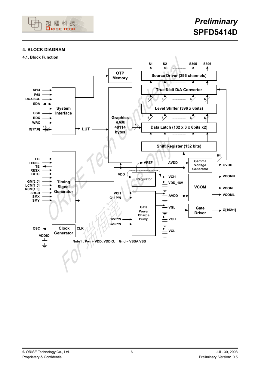
4. BLOCK DIAGRAM
4.1. Block Function
Preliminary
SPFD5414D
OTP
Memory
S1
S2
S395
S396
Source Driver (396 channels)
System
Interface
LUT
Graphics
RAM
48114
bytes
18
True 6-bit D/A Converter
6
6
Level Shifter (396 x 6bits)
6
6
6
6
6
6
Data Latch (132 x 3 x 6bits x2)
Shift Register (132 bits)
VREF
AVDD
64
Gamma
Voltage
Generator
SPI4
P68
DCX/SCL
SDA
CSX
RDX
WRX
D[17:0]
18
FB
TESEL
TE
RESX
EXTC
GM[2:0]
LCM[1:0]
RCM[1:0]
SRGB
SMX
SMY
Timing
Signal
Generator
VDD
Regulator
VCI1
C11P/N
C22P/N
C23P/N
Gate
Power
Charge
Pump
VCI1
VDD_18V
AVDD
VGL
VGH
VCL
VCOM
Gate
Driver
GVDD
VCOMH
VCOM
VCOML
G[162:1]
OSC
VDDIO
Clock
Generator
CLK
Note1 : Pwr = VDD, VDDIO; Gnd = VSSA,VSS
© ORISE Technology Co., Ltd.
Proprietary & Confidential
6
JUL. 30, 2008
Preliminary Version: 0.5
�
Preliminary
SPFD5414D
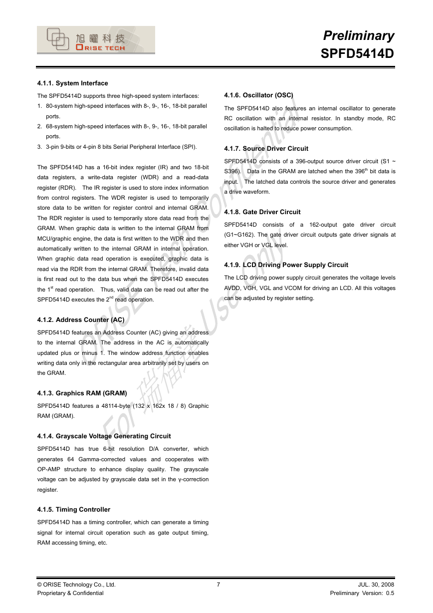
4.1.1. System Interface
4.1.6. Oscillator (OSC)
The SPFD5414D also features an internal oscillator to generate
RC oscillation with an internal resistor. In standby mode, RC
oscillation is halted to reduce power consumption.
4.1.7. Source Driver Circuit
SPFD5414D consists of a 396-output source driver circuit (S1 ~
S396). Data in the GRAM are latched when the 396th bit data is
input. The latched data controls the source driver and generates
a drive waveform.
4.1.8. Gate Driver Circuit
SPFD5414D consists of a 162-output gate driver circuit
(G1~G162). The gate driver circuit outputs gate driver signals at
either VGH or VGL level.
4.1.9. LCD Driving Power Supply Circuit
The LCD driving power supply circuit generates the voltage levels
AVDD, VGH, VGL and VCOM for driving an LCD. All this voltages
can be adjusted by register setting.
The SPFD5414D supports three high-speed system interfaces:
1. 80-system high-speed interfaces with 8-, 9-, 16-, 18-bit parallel
ports.
2. 68-system high-speed interfaces with 8-, 9-, 16-, 18-bit parallel
ports.
3. 3-pin 9-bits or 4-pin 8 bits Serial Peripheral Interface (SPI).
The SPFD5414D has a 16-bit index register (IR) and two 18-bit
data registers, a write-data register (WDR) and a read-data
register (RDR). The IR register is used to store index information
from control registers. The WDR register is used to temporarily
store data to be written for register control and internal GRAM.
The RDR register is used to temporarily store data read from the
GRAM. When graphic data is written to the internal GRAM from
MCU/graphic engine, the data is first written to the WDR and then
automatically written to the internal GRAM in internal operation.
When graphic data read operation is executed, graphic data is
read via the RDR from the internal GRAM. Therefore, invalid data
is first read out to the data bus when the SPFD5414D executes
the 1st read operation. Thus, valid data can be read out after the
SPFD5414D executes the 2nd read operation.
4.1.2. Address Counter (AC)
SPFD5414D features an Address Counter (AC) giving an address
to the internal GRAM. The address in the AC is automatically
updated plus or minus 1. The window address function enables
writing data only in the rectangular area arbitrarily set by users on
the GRAM.
4.1.3. Graphics RAM (GRAM)
SPFD5414D features a 48114-byte (132 x 162x 18 / 8) Graphic
RAM (GRAM).
4.1.4. Grayscale Voltage Generating Circuit
SPFD5414D has true 6-bit resolution D/A converter, which
generates 64 Gamma-corrected values and cooperates with
OP-AMP structure to enhance display quality. The grayscale
voltage can be adjusted by grayscale data set in the γ-correction
register.
4.1.5. Timing Controller
SPFD5414D has a timing controller, which can generate a timing
signal for internal circuit operation such as gate output timing,
RAM accessing timing, etc.
© ORISE Technology Co., Ltd.
Proprietary & Confidential
7
JUL. 30, 2008
Preliminary Version: 0.5
�
Preliminary
SPFD5414D
I/O Connected with Function
Select system interface mode.
SPI4
P68
IM2
IM1
IM0
0
-
-
-
-
-
-
-
-
-
0
0
0
0
0
1
1
1
1
1
0
1
1
1
1
0
1
1
1
1
-
0
0
1
1
-
0
0
1
1
-
0
1
0
1
-
0
1
0
1
1
-
Reset pin. This is an active low signal.
0
-
-
3-Pin Serial interface
8080 MCU 8-bits Parallel interface
8080 MCU 16-bits Parallel interface
8080 MCU 9-bits Parallel interface
8080 MCU 18-bits Parallel interface
3-Pin Serial interface
6800 MCU 8-bits Parallel interface
6800 MCU 16-bits Parallel interface
6800 MCU 9-bits Parallel interface
6800 MCU 18-bits Parallel interface
4-Pin Serial interface
Extend command set access
Low: Extend command set is not accessible.
High: Extend command set is accessible.
If this is not used. Open it (This pin is internally pull low).
Gamma Setting selection:
(a) Low: GC0=1.0, GC1=2.5, GC2=2.2, GC3=1.8.
(b) High: GC0=2.2, GC1=1.8, GC2=2.5, GC3=1.0.
Resolution selection:
Resolution
132*RGB*162
120*RGB*160
128*RGB*128
128*RGB*160
GM2
GM1
GM0
0
0
0
0
0
1
0
1
0
0
1
1
Reserved function
Must connect to VSS level
Liquid Crystal Type selection:
LCM1
LCM0
LC Type
0
0
1
0
1
0
TR
TM
TM-TYPE2
MVA
1
1
RGB arrangement selection:
(a) Low: S1, S2, S3 fit ‘R’, ‘G’, ‘B’.
(b) High: S1, S2, S3 fit ‘B’, ‘G’, ‘R’
8
JUL. 30, 2008
Preliminary Version: 0.5
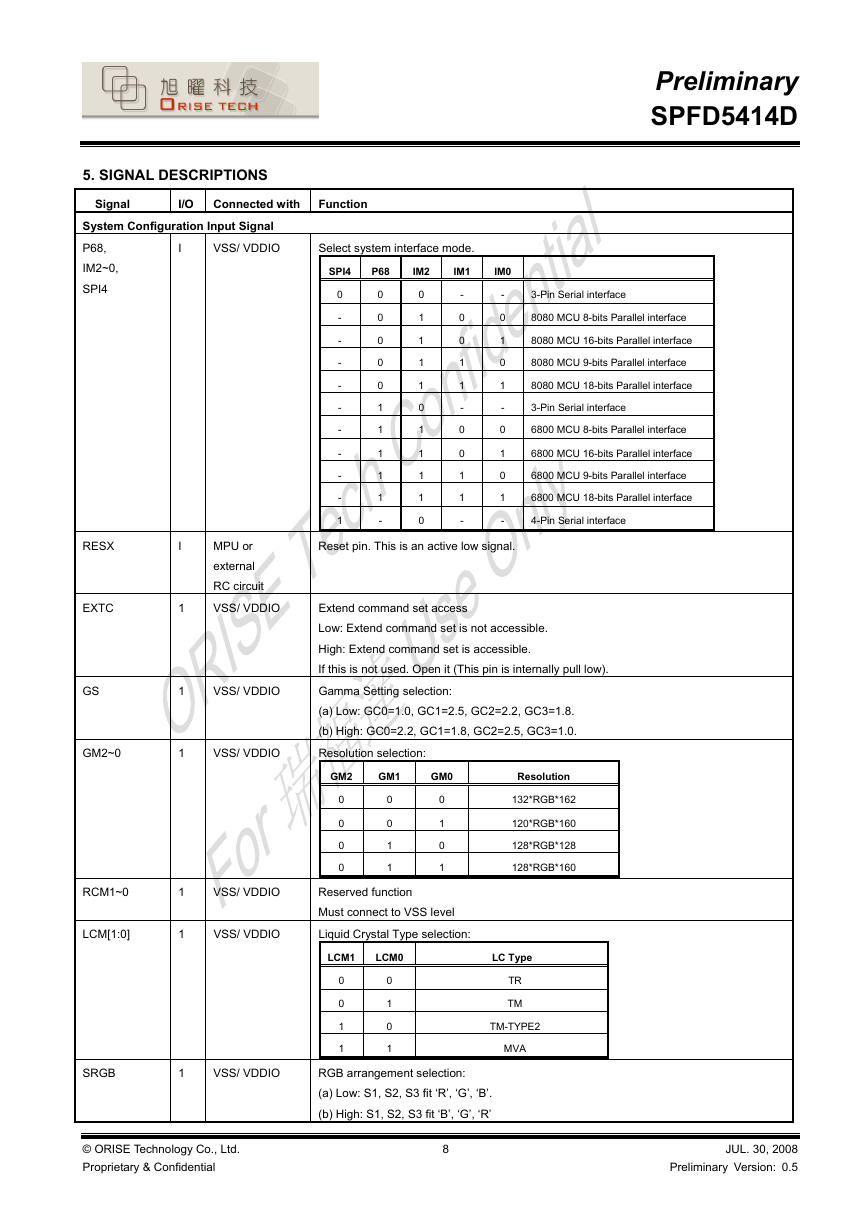
5. SIGNAL DESCRIPTIONS
Signal
System Configuration Input Signal
P68,
IM2~0,
SPI4
I
VSS/ VDDIO
RESX
EXTC
I
1
MPU or
external
RC circuit
VSS/ VDDIO
GS
1
VSS/ VDDIO
GM2~0
1
VSS/ VDDIO
RCM1~0
LCM[1:0]
1
1
VSS/ VDDIO
VSS/ VDDIO
SRGB
1
VSS/ VDDIO
© ORISE Technology Co., Ltd.
Proprietary & Confidential
�


 2023年江西萍乡中考道德与法治真题及答案.doc
 2012年重庆南川中考生物真题及答案.doc
 2013年江西师范大学地理学综合及文艺理论基础考研真题.doc
 2020年四川甘孜小升初语文真题及答案I卷.doc
 2020年注册岩土工程师专业基础考试真题及答案.doc
 2023-2024学年福建省厦门市九年级上学期数学月考试题及答案.doc
 2021-2022学年辽宁省沈阳市大东区九年级上学期语文期末试题及答案.doc
 2022-2023学年北京东城区初三第一学期物理期末试卷及答案.doc
 2018上半年江西教师资格初中地理学科知识与教学能力真题及答案.doc
 2012年河北国家公务员申论考试真题及答案-省级.doc
 2020-2021学年江苏省扬州市江都区邵樊片九年级上学期数学第一次质量检测试题及答案.doc
 2022下半年黑龙江教师资格证中学综合素质真题及答案.doc