Chapter 1: LPC24XX Introductory information
1. Introduction
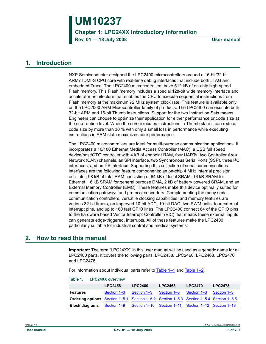
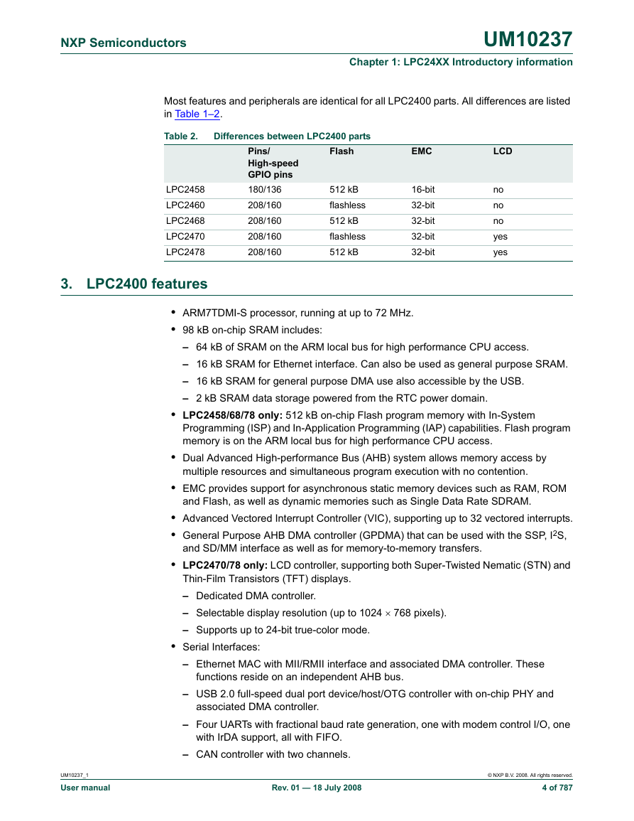
2. How to read this manual
3. LPC2400 features
4. Applications
5. Ordering options
5.1 LPC2458 ordering options
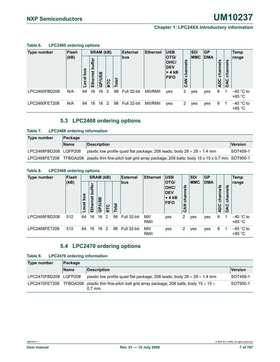
5.2 LPC2460 ordering options
5.3 LPC2468 ordering options
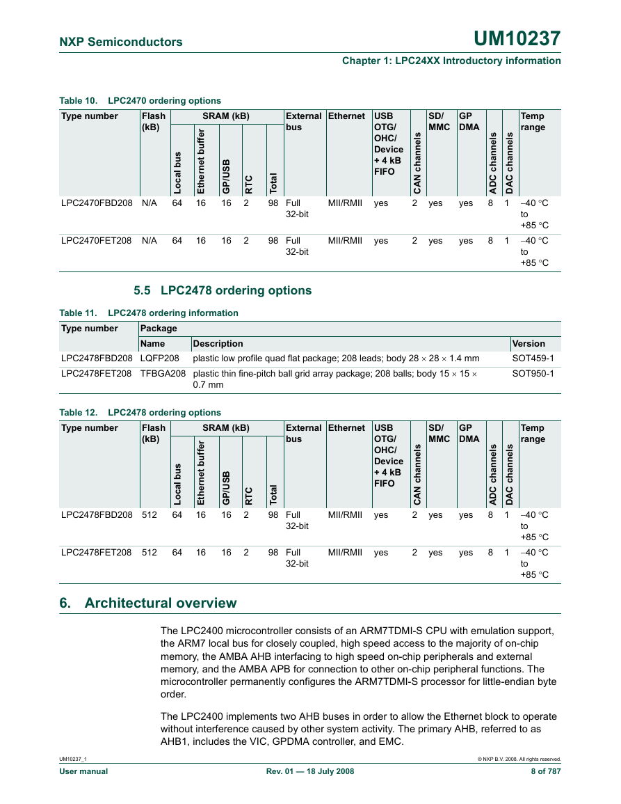
5.4 LPC2470 ordering options
5.5 LPC2478 ordering options
6. Architectural overview
7. On-chip flash programming memory (LPC2458/68/78)
8. On-chip SRAM
9. LPC2458 block diagram
10. LPC2460 block diagram
11. LPC2468 block diagram
12. LPC2470 block diagram
13. LPC2478 block diagram
Chapter 2: LPC24XX Memory mapping
1. How to read this chapter
2. Memory map and peripheral addressing
3. Memory maps
4. APB peripheral addresses
5. LPC2400 memory re-mapping and boot ROM
5.1 Memory map concepts and operating modes
5.2 Memory re-mapping
6. Memory mapping control
6.1 Memory Mapping Control Register (MEMMAP - 0xE01F C040)
6.2 Memory mapping control usage notes
7. Prefetch abort and data abort exceptions
Chapter 3: LPC24XX System control
1. Summary of system control block functions
2. Pin description
3. Register description
3.1 External interrupt inputs
3.2 Reset
3.3 Other system controls and status flags
4. Brown-out detection
5. Code security vs. debugging
Chapter 4: LPC24XX Clocking and power control
1. Summary of clocking and power control functions
2. Oscillators
2.1 Internal RC oscillator
2.2 Main oscillator
2.3 RTC oscillator
3. Register description
3.1 Clock source selection multiplexer
3.2 PLL (Phase Locked Loop)
3.3 Clock dividers
3.4 Power control
4. Power domains
5. Wakeup timer
Chapter 5: LPC24XX External Memory Controller (EMC)
1. How to read this chapter
2. Basic configuration
3. Introduction
4. Features
5. EMC functional description
5.1 AHB slave register interface
5.2 AHB slave memory interface
5.3 Pad interface
5.4 Data buffers
5.5 Memory controller state machine
6. Low-power operation
6.1 Low-power SDRAM Deep-sleep Mode
6.2 Low-power SDRAM partial array refresh
7. Memory bank select
8. Reset
9. Pin description
10. Register description
10.1 EMC Control register (EMCControl - 0xFFE0 8000)
10.2 EMC Status register (EMCStatus - 0xFFE0 8004)
10.3 EMC Configuration register (EMCConfig - 0xFFE0 8008)
10.4 Dynamic Memory Control register (EMCDynamicControl - 0xFFE0 8020)
10.5 Dynamic Memory Refresh Timer register (EMCDynamicRefresh - 0xFFE0 8024)
10.6 Dynamic Memory Read Configuration register (EMCDynamicReadConfig - 0xFFE0 8028)
10.7 Dynamic Memory Percentage Command Period register (EMCDynamictRP - 0xFFE0 8030)
10.8 Dynamic Memory Active to Precharge Command Period register (EMCDynamictRAS - 0xFFE0 8034)
10.9 Dynamic Memory Self-refresh Exit Time register (EMCDynamictSREX - 0xFFE0 8038)
10.10 Dynamic Memory Last Data Out to Active Time register (EMCDynamictAPR - 0xFFE0 803C)
10.11 Dynamic Memory Data-in to Active Command Time register (EMCDynamictDAL - 0xFFE0 8040)
10.12 Dynamic Memory Write Recovery Time register (EMCDynamictWR - 0xFFE0 8044)
10.13 Dynamic Memory Active to Active Command Period register (EMCDynamictRC - 0xFFE0 8048)
10.14 Dynamic Memory Auto-refresh Period register (EMCDynamictRFC - 0xFFE0 804C)
10.15 Dynamic Memory Exit Self-refresh register (EMCDynamictXSR - 0xFFE0 8050)
10.16 Dynamic Memory Active Bank A to Active Bank B Time register (EMCDynamictRRD - 0xFFE0 8054)
10.17 Dynamic Memory Load Mode register to Active Command Time (EMCDynamictMRD - 0xFFE0 8058)
10.18 Static Memory Extended Wait register (EMCStaticExtendedWait - 0xFFE0 8080)
10.19 Dynamic Memory Configuration registers (EMCDynamicConfig0-3 - 0xFFE0 8100, 120, 140, 160)
10.20 Dynamic Memory RAS & CAS Delay registers (EMCDynamicRASCAS0-3 - 0xFFE0 8104, 124, 144, 164)
10.21 Static Memory Configuration registers (EMCStaticConfig0-3 - 0xFFE0 8200, 220, 240, 260)
10.22 Static Memory Write Enable Delay registers (EMCStaticWaitWen0-3 - 0xFFE0 8204, 224, 244 ,264)
10.23 Static Memory Output Enable Delay registers (EMCStaticWaitOen0-3 - 0xFFE0 8208, 228, 248, 268)
10.24 Static Memory Read Delay registers (EMCStaticWaitRd0-3 - 0xFFE0 820C, 22C, 24C, 26C)
10.25 Static Memory Page Mode Read Delay registers (EMCStaticwaitPage0-3 - 0xFFE0 8210, 230, 250, 270)
10.26 Static Memory Write Delay registers (EMCStaticWaitwr0-3 - 0xFFE0 8214, 234, 254, 274)
10.27 Static Memory Turn Round Delay registers (EMCStaticWaitTurn0-3 - 0xFFE0 8218, 238, 258, 278)
11. External memory interface
11.1 32-bit wide memory bank connection
11.2 16-bit wide memory bank connection
11.3 8-bit wide memory bank connection
11.4 Memory configuration example
Chapter 6: LPC24XX Memory Accelerator Module (MAM)
1. How to read this chapter
2. Introduction
3. Operation
4. Memory Acceleration Module blocks
4.1 Flash memory bank
4.2 Instruction latches and data latches
4.3 Flash programming Issues
5. Memory Accelerator Module operating modes
6. MAM configuration
7. Register description
7.1 MAM Control Register (MAMCR - 0xE01F C000)
7.2 MAM Timing Register (MAMTIM - 0xE01F C004)
8. MAM usage notes
Chapter 7: LPC24XX Vectored Interrupt Controller (VIC)
1. Features
2. Description
3. Register description
3.1 Software Interrupt Register (VICSoftInt - 0xFFFF F018)
3.2 Software Interrupt Clear Register (VICSoftIntClear - 0xFFFF F01C)
3.3 Raw Interrupt Status Register (VICRawIntr - 0xFFFF F008)
3.4 Interrupt Enable Register (VICIntEnable - 0xFFFF F010)
3.5 Interrupt Enable Clear Register (VICIntEnClear - 0xFFFF F014)
3.6 Interrupt Select Register (VICIntSelect - 0xFFFF F00C)
3.7 IRQ Status Register (VICIRQStatus - 0xFFFF F000)
3.8 FIQ Status Register (VICFIQStatus - 0xFFFF F004)
3.9 Vector Address Registers 0-31 (VICVectAddr0-31 - 0xFFFF F100 to 17C)
3.10 Vector Priority Registers 0-31 (VICVectPriority0-31 - 0xFFFF F200 to 27C)
3.11 Vector Address Register (VICAddress - 0xFFFF FF00)
3.12 Software Priority Mask Register (VICSWPriorityMask - 0xFFFF F024)
3.13 Protection Enable Register (VICProtection - 0xFFFF F020)
4. Interrupt sources
Chapter 8: LPC24XX Pin configuration
1. How to read this chapter
2. LPC2400 pin packages
2.1 LPC2400 180-pin package
2.2 LPC2400 208-pin packages
3. LPC2458 pinning information
4. LPC2460/68 pinning information
5. LPC2470/78 pinning information
6. LPC2460/70 boot control
Chapter 9: LPC24XX Pin connect
1. How to read this chapter
2. Description
3. Pin function select register values
4. Pin mode select register values
5. Register description
5.1 Pin Function Select register 0 (PINSEL0 - 0xE002 C000)
5.2 Pin Function Select Register 1 (PINSEL1 - 0xE002 C004)
5.3 Pin Function Select register 2 (PINSEL2 - 0xE002 C008)
5.4 Pin Function Select Register 3 (PINSEL3 - 0xE002 C00C)
5.5 Pin Function Select Register 4 (PINSEL4 - 0xE002 C010)
5.6 Pin Function Select Register 5 (PINSEL5 - 0xE002 C014)
5.7 Pin Function Select Register 6 (PINSEL6 - 0xE002 C018)
5.8 Pin Function Select Register 7 (PINSEL7 - 0xE002 C01C)
5.9 Pin Function Select Register 8 (PINSEL8 - 0xE002 C020)
5.10 Pin Function Select Register 9 (PINSEL9 - 0xE002 C024)
5.11 Pin Function Select Register 10 (PINSEL10 - 0xE002 C028)
5.12 Pin Function Select Register 11 (PINSEL11 - 0xE002 C02C)
5.13 Pin Mode select register 0 (PINMODE0 - 0xE002 C040)
5.14 Pin Mode select register 1 (PINMODE1 - 0xE002 C044)
5.15 Pin Mode select register 2 (PINMODE2 - 0xE002 C048)
5.16 Pin Mode select register 3 (PINMODE3 - 0xE002 C04C)
5.17 Pin Mode select register 4 (PINMODE4 - 0xE002 C050)
5.18 Pin Mode select register 5 (PINMODE5 - 0xE002 C054)
5.19 Pin Mode select register 6 (PINMODE6 - 0xE002 C058)
5.20 Pin Mode select register 7 (PINMODE7 - 0xE002 C05C)
5.21 Pin Mode select register 8 (PINMODE8 - 0xE002 C060)
5.22 Pin Mode select register 9 (PINMODE9 - 0xE002 C064)
Chapter 10: LPC24XX General Purpose Input/Output (GPIO)
1. How to read this chapter
2. Basic configuration
3. Features
3.1 Digital I/O ports
3.2 Interrupt generating digital ports
4. Applications
5. Pin description
6. Register description
6.1 GPIO port Direction register IODIR and FIODIR(IO[0/1]DIR - 0xE002 80[0/1]8 and FIO[0/1/2/3/4]DIR - 0x3FFF C0[0/2/4/6/8]0)
6.2 GPIO port output Set register IOSET and FIOSET(IO[0/1]SET - 0xE002 80[0/1]4 and FIO[0/1/2/3/4]SET - 0x3FFF C0[1/3/5/7/9]8)
6.3 GPIO port output Clear register IOCLR and FIOCLR (IO[0/1]CLR - 0xE002 80[0/1]C and FIO[0/1/2/3/4]CLR - 0x3FFF C0[1/3/5/7/9]C)
6.4 GPIO port Pin value register IOPIN and FIOPIN (IO[0/1]PIN - 0xE002 80[0/1]0 and FIO[0/1/2/3/4]PIN - 0x3FFF C0[1/3/5/7/9]4)
6.5 Fast GPIO port Mask register FIOMASK(FIO[0/1/2/3/4]MASK - 0x3FFF C0[1/3/5/7/9]0)
6.6 GPIO interrupt registers
7. GPIO usage notes
7.1 Example 1: sequential accesses to IOSET and IOCLR affecting the same GPIO pin/bit
7.2 Example 2: an instantaneous output of 0s and 1s on a GPIO port
7.3 Writing to IOSET/IOCLR vs. IOPIN
7.4 Output signal frequency considerations when using the legacy and enhanced GPIO registers
Chapter 11: LPC24XX Ethernet
1. Basic configuration
2. Introduction
3. Features
4. Ethernet architecture
4.1 Partitioning
4.2 Example PHY Devices
4.3 DMA engine functions
4.4 Overview of DMA operation
4.5 Ethernet Packet
5. Pin description
6. Register description
6.1 Ethernet MAC register definitions
6.2 Control register definitions
6.3 Receive filter register definitions
6.4 Module control register definitions
7. Descriptor and status formats
7.1 Receive descriptors and statuses
7.2 Transmit descriptors and statuses
8. Ethernet block functional description
8.1 Overview
8.2 AHB interface
8.3 Interrupts
8.4 Direct Memory Access (DMA)
8.5 Initialization
8.6 Transmit process
8.7 Receive process
8.8 Transmission retry
8.9 Status hash CRC calculations
8.10 Duplex modes
8.11 IEE 802.3/Clause 31 flow control
8.12 Half-Duplex mode backpressure
8.13 Receive filtering
8.14 Power management
8.15 Wake-up on LAN
8.16 Enabling and disabling receive and transmit
8.17 Transmission padding and CRC
8.18 Huge frames and frame length checking
8.19 Statistics counters
8.20 MAC status vectors
8.21 Reset
8.22 Ethernet errors
8.23 AHB bandwidth
8.24 CRC calculation
Chapter 12: LPC24XX LCD controller
1. How to read this chapter
2. Basic configuration
3. Introduction
4. Features
5. Programmable parameters
6. Hardware cursor support
7. Types of LCD panels supported
8. TFT panels
9. Color STN panels
10. Monochrome STN panels
11. Pin descriptions
11.1 Signal usage
12. LCD controller functional description
12.1 AHB interfaces
12.2 Dual DMA FIFOs and associated control logic
12.3 Pixel serializer
12.4 RAM palette
12.5 Hardware cursor
12.6 Gray scaler
12.7 Upper and lower panel formatters
12.8 Panel clock generator
12.9 Timing controller
12.10 STN and TFT data select
12.11 Interrupt generation
12.12 LCD power up and power down sequence
13. Register description
13.1 LCD Configuration register (LCD_CFG, RW - 0xE01F C1B8)
13.2 Horizontal Timing register (LCD_TIMH, RW - 0xFFE1 0000)
13.3 Vertical Timing register (LCD_TIMV, RW - 0xFFE1 0004)
13.4 Clock and Signal Polarity register (LCD_POL, RW - 0xFFE1 0008)
13.5 Line End Control register (LCD_LE, RW - 0xFFE1 000C)
13.6 Upper Panel Frame Base Address register (LCD_UPBASE, RW - 0xFFE1 0010)
13.7 Lower Panel Frame Base Address register (LCD_LPBASE, RW - 0xFFE1 0014)
13.8 LCD Control register (LCD_CTRL, RW - 0xFFE1 0018)
13.9 Interrupt Mask register (LCD_INTMSK, RW - 0xFFE1 001C)
13.10 Raw Interrupt Status register (LCD_INTRAW, RW - 0xFFE1 0020)
13.11 Masked Interrupt Status register (LCD_INTSTAT, RW - 0xFFE1 0024)
13.12 Interrupt Clear register (LCD_INTCLR, RW - 0xFFE1 0028)
13.13 Upper Panel Current Address register (LCD_UPCURR, RW - 0xFFE1 002C)
13.14 Lower Panel Current Address register (LCD_LPCURR, RW - 0xFFE1 0030)
13.15 Color Palette registers (LCD_PAL, RW - 0xFFE1 0200 to 0xFFE1 03FC)
13.16 Cursor Image registers (CRSR_IMG, RW - 0xFFE1 0800 to 0xFFE1 0BFC)
13.17 Cursor Control register (CRSR_CTRL, RW - 0xFFE1 0C00)
13.18 Cursor Configuration register (CRSR_CFG, RW - 0xFFE1 0C04)
13.19 Cursor Palette register 0 (CRSR_PAL0, RW - 0xFFE1 0C08)
13.20 Cursor Palette register 1 (CRSR_PAL1, RW - 0xFFE1 0C0C)
13.21 Cursor XY Position register (CRSR_XY, RW - 0xFFE1 0C10)
13.22 Cursor Clip Position register (CRSR_CLIP, RW - 0xFFE1 0C14)
13.23 Cursor Interrupt Mask register (CRSR_INTMSK, RW - 0xFFE1 0C20)
13.24 Cursor Interrupt Clear register (CRSR_INTCLR, RW - 0xFFE1 0C24)
13.25 Cursor Raw Interrupt Status register (CRSR_INTRAW, RW - 0xFFE1 0C28)
13.26 Cursor Masked Interrupt Status register (CRSR_INTSTAT, RW - 0xFFE1 0C2C)
14. LCD timing diagrams
15. LCD panel signal usage
Chapter 13: LPC24XX USB device controller
1. Basic configuration
2. Introduction
3. Features
4. Fixed endpoint configuration
5. Functional description
5.1 Analog transceiver
5.2 Serial Interface Engine (SIE)
5.3 Endpoint RAM (EP_RAM)
5.4 EP_RAM access control
5.5 DMA engine and bus master interface
5.6 Register interface
5.7 SoftConnect
5.8 GoodLink
6. Operational overview
7. Pin description
7.1 USB device usage note
8. Clocking and power management
8.1 Power requirements
8.2 Clocks
8.3 Power management support
8.4 Remote wake-up
9. Register description
9.1 Port select register
9.2 Clock control registers
9.3 Device interrupt registers
9.4 Endpoint interrupt registers
9.5 Endpoint realization registers
9.6 USB transfer registers
9.7 SIE command code registers
9.8 DMA registers
10. Interrupt handling
11. Serial interface engine command description
11.1 Set Address (Command: 0xD0, Data: write 1 byte)
11.2 Configure Device (Command: 0xD8, Data: write 1 byte)
11.3 Set Mode (Command: 0xF3, Data: write 1 byte)
11.4 Read Current Frame Number (Command: 0xF5, Data: read 1 or 2 bytes)
11.5 Read Test Register (Command: 0xFD, Data: read 2 bytes)
11.6 Set Device Status (Command: 0xFE, Data: write 1 byte)
11.7 Get Device Status (Command: 0xFE, Data: read 1 byte)
11.8 Get Error Code (Command: 0xFF, Data: read 1 byte)
11.9 Read Error Status (Command: 0xFB, Data: read 1 byte)
11.10 Select Endpoint (Command: 0x00 - 0x1F, Data: read 1 byte (optional))
11.11 Select Endpoint/Clear Interrupt (Command: 0x40 - 0x5F, Data: read 1 byte)
11.12 Set Endpoint Status (Command: 0x40 - 0x55, Data: write 1 byte (optional))
11.13 Clear Buffer (Command: 0xF2, Data: read 1 byte (optional))
11.14 Validate Buffer (Command: 0xFA, Data: none)
12. USB device controller initialization
13. Slave mode operation
13.1 Interrupt generation
13.2 Data transfer for OUT endpoints
13.3 Data transfer for IN endpoints
14. DMA operation
14.1 Transfer terminology
14.2 USB device communication area
14.3 Triggering the DMA engine
14.4 The DMA descriptor
14.5 Non-isochronous endpoint operation
14.6 Isochronous endpoint operation
14.7 Auto Length Transfer Extraction (ATLE) mode operation
15. Double buffered endpoint operation
15.1 Bulk endpoints
15.2 Isochronous endpoints
Chapter 14: LPC24XX USB Host controller
1. Basic configuration
2. Introduction
2.1 Features
2.2 Architecture
3. Interfaces
3.1 Pin description
3.2 Software interface
Chapter 15: LPC24XX USB OTG controller
1. Basic configuration
2. Introduction
3. Features
4. Architecture
5. Modes of operation
6. Pin configuration
6.1 Connecting port U1 to an external OTG transceiver
6.2 Connecting USB as a two-port host
6.3 Connecting USB as one port host and one port device
7. Register description
7.1 USB Interrupt Status Register (USBIntSt - 0xE01F C1C0)
7.2 OTG Interrupt Status Register (OTGIntSt - 0xE01F C100)
7.3 OTG Interrupt Enable Register (OTGIntEn - 0xFFE0 C104)
7.4 OTG Interrupt Set Register (OTGIntSet - 0xFFE0 C20C)
7.5 OTG Interrupt Clear Register (OTGIntClr - 0xFFE0 C10C)
7.6 OTG Status and Control Register (OTGStCtrl - 0xFFE0 C110)
7.7 OTG Timer Register (OTGTmr - 0xFFE0 C114)
7.8 OTG Clock Control Register (OTGClkCtrl - 0xFFE0 CFF4)
7.9 OTG Clock Status Register (OTGClkSt - 0xFFE0 CFF8)
7.10 I2C Receive Register (I2C_RX - 0xFFE0 C300)
7.11 I2C Transmit Register (I2C_TX - 0xFFE0 C300)
7.12 I2C Status Register (I2C_STS - 0xFFE0 C304)
7.13 I2C Control Register (I2C_CTL - 0xFFE0 C308)
7.14 I2C Clock High Register (I2C_CLKHI - 0xFFE0 C30C)
7.15 I2C Clock Low Register (I2C_CLKLO - 0xFFE0 C310)
7.16 Interrupt handling
8. HNP support
8.1 B-device: peripheral to host switching
8.2 A-device: host to peripheral HNP switching
9. Clocking and power management
9.1 Device clock request signals
9.2 Power-down mode support
10. USB OTG controller initialization
Chapter 16: LPC24XX Universal Asynchronous Receiver/Transmitter (UART) 0/2/3
1. Basic configuration
2. Features
3. Pin description
4. Register description
16.4.1 UARTn Receiver Buffer Register (U0RBR - 0xE000 C000, U2RBR - 0xE007 8000, U3RBR - 0xE007 C000 when DLAB = 0, Read Only)
4.2 UARTn Transmit Holding Register (U0THR - 0xE000 C000, U2THR - 0xE007 8000, U3THR - 0xE007 C000 when DLAB = 0, Write Only)
4.3 UARTn Divisor Latch LSB Register (U0DLL - 0xE000 C000, U2DLL - 0xE007 8000, U3DLL - 0xE007 C000 when DLAB = 1) and UARTn Divisor Latch MSB Register (U0DLM - 0xE000 C004, U2DLL - 0xE007 8004, U3DLL - 0xE007 C004 when DLAB = 1)
4.4 UARTn Interrupt Enable Register (U0IER - 0xE000 C004, U2IER - 0xE007 8004, U3IER - 0xE007 C004 when DLAB = 0)
4.5 UARTn Interrupt Identification Register (U0IIR - 0xE000 C008, U2IIR - 0xE007 8008, U3IIR - 0x7008 C008, Read Only)
4.6 UARTn FIFO Control Register (U0FCR - 0xE000 C008, U2FCR - 0xE007 8008, U3FCR - 0xE007 C008, Write Only)
4.7 UARTn Line Control Register (U0LCR - 0xE000 C00C, U2LCR - 0xE007 800C, U3LCR - 0xE007 C00C)
4.8 UARTn Line Status Register (U0LSR - 0xE000 C014, U2LSR - 0xE007 8014, U3LSR - 0xE007 C014, Read Only)
4.9 UARTn Scratch Pad Register (U0SCR - 0xE000 C01C, U2SCR - 0xE007 801C U3SCR - 0xE007 C01C)
4.10 UARTn Auto-baud Control Register (U0ACR - 0xE000 C020, U2ACR - 0xE007 8020, U3ACR - 0xE007 C020)
4.11 IrDA Control Register for UART3 Only (U3ICR - 0xE007 C024)
4.12 UARTn Fractional Divider Register (U0FDR - 0xE000 C028, U2FDR - 0xE007 8028, U3FDR - 0xE007 C028)
4.13 UARTn Transmit Enable Register (U0TER - 0xE000 C030, U2TER - 0xE007 8030, U3TER - 0xE007 C030)
5. Architecture
Chapter 17: LPC24XX Universal Asynchronous Receiver/Transmitter (UART) 1
1. Basic configuration
2. Features
3. Pin description
4. Register description
4.1 UART1 Receiver Buffer Register (U1RBR - 0xE001 0000, when DLAB = 0 Read Only)
4.2 UART1 Transmitter Holding Register (U1THR - 0xE001 0000 when DLAB = 0, Write Only)
4.3 UART1 Divisor Latch LSB and MSB Registers (U1DLL - 0xE001 0000 and U1DLM - 0xE001 0004, when DLAB = 1)
4.4 UART1 Interrupt Enable Register (U1IER - 0xE001 0004, when DLAB = 0)
4.5 UART1 Interrupt Identification Register (U1IIR - 0xE001 0008, Read Only)
4.6 UART1 FIFO Control Register (U1FCR - 0xE001 0008, Write Only)
4.7 UART1 Line Control Register (U1LCR - 0xE001 000C)
4.8 UART1 Modem Control Register (U1MCR - 0xE001 0010)
4.9 Auto-flow control
4.10 UART1 Line Status Register (U1LSR - 0xE001 0014, Read Only)
4.11 UART1 Modem Status Register (U1MSR - 0xE001 0018)
4.12 UART1 Scratch Pad Register (U1SCR - 0xE001 001C)
4.13 UART1 Auto-baud Control Register (U1ACR - 0xE001 0020)
4.14 Auto-baud
4.15 Auto-baud modes
4.16 UART1 Fractional Divider Register (U1FDR - 0xE001 0028)
4.17 UART1 Transmit Enable Register (U1TER - 0xE001 0030)
5. Architecture
Chapter 18: LPC24XX CAN controllers CAN1/2
1. Basic configuration
2. CAN controllers
3. Features
3.1 General CAN features
3.2 CAN controller features
3.3 Acceptance filter features
4. Pin description
5. CAN controller architecture
5.1 APB Interface Block (AIB)
5.2 Interface Management Logic (IML)
5.3 Transmit Buffers (TXB)
5.4 Receive Buffer (RXB)
5.5 Error Management Logic (EML)
5.6 Bit Timing Logic (BTL)
5.7 Bit Stream Processor (BSP)
5.8 CAN controller self-tests
6. Memory map of the CAN block
7. Register description
7.1 Mode Register (CAN1MOD - 0xE004 4000, CAN2MOD - 0xE004 8000)
7.2 Command Register (CAN1CMR - 0xE004 x004, CAN2CMR - 0xE004 8004)
7.3 Global Status Register (CAN1GSR - 0xE004 x008, CAN2GSR - 0xE004 8008)
7.4 Interrupt and Capture Register (CAN1ICR - 0xE004 400C, CAN2ICR - 0xE004 800C)
7.5 Interrupt Enable Register (CAN1IER - 0xE004 4010, CAN2IER - 0xE004 8010)
7.6 Bus Timing Register (CAN1BTR - 0xE004 4014, CAN2BTR - 0xE004 8014)
7.7 Error Warning Limit Register (CAN1EWL - 0xE004 4018, CAN2EWL - 0xE004 8018)
7.8 Status Register (CAN1SR - 0xE004 401C, CAN2SR - 0xE004 801C)
7.9 Receive Frame Status Register (CAN1RFS - 0xE004 4020, CAN2RFS - 0xE004 8020)
7.10 Receive Identifier Register (CAN1RID - 0xE004 4024, CAN2RID - 0xE004 8024)
7.11 Receive Data Register A (CAN1RDA - 0xE004 4028, CAN2RDA - 0xE004 8028)
7.12 Receive Data Register B (CAN1RDB - 0xE004 402C, CAN2RDB - 0xE004 802C)
7.13 Transmit Frame Information Register (CAN1TFI[1/2/3] - 0xE004 40[30/ 40/50], CAN2TFI[1/2/3] - 0xE004 80[30/40/50])
7.14 Transmit Identifier Register (CAN1TID[1/2/3] - 0xE004 40[34/44/54], CAN2TID[1/2/3] - 0xE004 80[34/44/54])
7.15 Transmit Data Register A (CAN1TDA[1/2/3] - 0xE004 40[38/48/58], CAN2TDA[1/2/3] - 0xE004 80[38/48/58])
7.16 Transmit Data Register B (CAN1TDB[1/2/3] - 0xE004 40[3C/4C/5C], CAN2TDB[1/2/3] - 0xE004 80[3C/4C/5C])
8. CAN controller operation
8.1 Error handling
8.2 Sleep mode
8.3 Interrupts
8.4 Transmit priority
9. Centralized CAN registers
9.1 Central Transmit Status Register (CANTxSR - 0xE004 0000)
9.2 Central Receive Status Register (CANRxSR - 0xE004 0004)
9.3 Central Miscellaneous Status Register (CANMSR - 0xE004 0008)
10. Global acceptance filter
11. Acceptance filter modes
11.1 Acceptance filter Off mode
11.2 Acceptance filter Bypass mode
11.3 Acceptance filter Operating mode
11.4 FullCAN mode
12. Sections of the ID look-up table RAM
13. ID look-up table RAM
14. Acceptance filter registers
14.1 Acceptance Filter Mode Register (AFMR - 0xE003 C000)
14.2 Section configuration registers
14.3 Standard Frame Individual Start Address Register (SFF_sa - 0xE003 C004)
14.4 Standard Frame Group Start Address Register (SFF_GRP_sa - 0xE003 C008)
14.5 Extended Frame Start Address Register (EFF_sa - 0xE003 C00C)
14.6 Extended Frame Group Start Address Register (EFF_GRP_sa - 0xE003 C010)
14.7 End of AF Tables Register (ENDofTable - 0xE003 C014)
14.8 Status registers
14.9 LUT Error Address Register (LUTerrAd - 0xE003 C018)
14.10 LUT Error Register (LUTerr - 0xE003 C01C)
14.11 Global FullCANInterrupt Enable register (FCANIE - 0xE003 C020)
14.12 FullCAN Interrupt and Capture registers (FCANIC0 - 0xE003 C024 and FCANIC1 - 0xE003 C028)
15. Configuration and search algorithm
15.1 Acceptance filter search algorithm
16. FullCAN mode
16.1 FullCAN message layout
16.2 FullCAN interrupts
16.3 Set and clear mechanism of the FullCAN interrupt
17. Examples of acceptance filter tables and ID index values
17.1 Example 1: only one section is used
17.2 Example 2: all sections are used
17.3 Example 3: more than one but not all sections are used
17.4 Configuration example 4
17.5 Configuration example 5
17.6 Configuration example 6
17.7 Configuration example 7
17.8 Look-up table programming guidelines
Chapter 19: LPC24XX SPI
1. Basic configuration
2. Features
3. SPI overview
4. SPI data transfers
5. SPI peripheral details
5.1 General information
5.2 Master operation
5.3 Slave operation
5.4 Exception conditions
6. Pin description
7. Register description
7.1 SPI Control Register (S0SPCR - 0xE002 0000)
7.2 SPI Status Register (S0SPSR - 0xE002 0004)
7.3 SPI Data Register (S0SPDR - 0xE002 0008)
7.4 SPI Clock Counter Register (S0SPCCR - 0xE002 000C)
7.5 SPI Test Control Register (SPTCR - 0xE002 0010)
7.6 SPI Test Status Register (SPTSR - 0xE002 0014)
7.7 SPI Interrupt Register (S0SPINT - 0xE002 001C)
8. Architecture
Chapter 20: LPC24XX SSP interface SSP0/1
1. Basic configuration
2. Features
3. Description
4. Pin descriptions
5. Bus description
5.1 Texas Instruments synchronous serial frame format
5.2 SPI frame format
5.3 Semiconductor Microwire frame format
6. Register description
6.1 SSPn Control Register 0 (SSP0CR0 - 0xE006 8000, SSP1CR0 - 0xE003 0000)
6.2 SSPn Control Register 1 (SSP0CR1 - 0xE006 8004, SSP1CR1 - 0xE003 0004)
6.3 SSPn Data Register (SSP0DR - 0xE006 8008, SSP1DR - 0xE003 0008)
6.4 SSPn Status Register (SSP0SR - 0xE006 800C, SSP1SR - 0xE003 000C)
6.5 SSPn Clock Prescale Register (SSP0CPSR - 0xE006 8010, SSP1CPSR - 0xE003 0010)
6.6 SSPn Interrupt Mask Set/Clear Register (SSP0IMSC - 0xE006 8014, SSP1IMSC - 0xE003 0014)
6.7 SSPn Raw Interrupt Status Register (SSP0RIS - 0xE006 8018, SSP1RIS - 0xE003 0018)
6.8 SSPn Masked Interrupt Status Register (SSP0MIS - 0xE006 801C, SSP1MIS - 0xE003 001C)
6.9 SSPn Interrupt Clear Register (SSP0ICR - 0xE006 8020, SSP1ICR - 0xE003 0020)
6.10 SSPn DMA Control Register (SSP0DMACR - 0xE006 8024, SSP1DMACR - 0xE003 0024)
Chapter 21: LPC24XX SD/MMC card interface
1. Basic configuration
2. Introduction
3. Features of the MCI
4. SD/MMC card interface pin description
5. Functional overview
5.1 Mutimedia card
5.2 Secure digital memory card
5.2.1 Secure digital memory card bus signals
5.3 MCI adapter
5.3.1 Adapter register block
5.3.2 Control unit
5.3.3 Command path
5.3.4 Command path state machine
5.3.5 Command format
5.3.6 Data path
5.3.7 Data path state machine
5.3.8 Data counter
5.3.9 Bus mode
5.3.10 CRC Token status
5.3.11 Status flags
5.3.12 CRC generator
5.3.13 Data FIFO
5.3.14 Transmit FIFO
5.3.15 Receive FIFO
5.3.16 APB interfaces
5.3.17 Interrupt logic
6. Register description
6.1 Power Control Register (MCI Power - 0xE008 C000)
6.2 Clock Control Register (MCIClock - 0xE008 C004)
6.3 Argument Register (MCIArgument - 0xE008 C008)
6.4 Command Register (MCICommand - 0xE008 C00C)
6.5 Command Response Register (MCIRespCommand - 0xE008 C010)
6.6 Response Registers (MCIResponse0-3 - 0xE008 C014, E008 C018, E008 C01C and E008 C020)
6.7 Data Timer Register (MCIDataTimer - 0xE008 C024)
6.8 Data Length Register (MCIDataLength - 0xE008 C028)
6.9 Data Control Register (MCIDataCtrl - 0xE008 C02C)
6.10 Data Counter Register (MCIDataCnt - 0xE008 C030)
6.11 Status Register (MCIStatus - 0xE008 C034)
6.12 Clear Register (MCIClear - 0xE008 C038)
6.13 Interrupt Mask Registers (MCIMask0 - 0xE008 C03C)
6.14 FIFO Counter Register (MCIFifoCnt - 0xE008 C048)
6.15 Data FIFO Register (MCIFIFO - 0xE008 C080 to 0xE008 C0BC)
Chapter 22: LPC24XX I2C interfaces I2C0/1/2
1. Basic configuration
2. Features
3. Applications
4. Description
5. Pin description
6. I2C operating modes
6.1 Master Transmitter mode
6.2 Master Receiver mode
6.3 Slave Receiver mode
6.4 Slave Transmitter mode
7. I2C implementation and operation
7.1 Input filters and output stages
7.2 Address Register I2ADDR
7.3 Comparator
7.4 Shift register I2DAT
7.5 Arbitration and synchronization logic
7.6 Serial clock generator
7.7 Timing and control
7.8 Control register I2CONSET and I2CONCLR
7.9 Status decoder and status register
8. Register description
8.1 I2C Control Set Register (I2C[0/1/2]CONSET: 0xE001 C000, 0xE005 C000, 0xE008 0000)
8.2 I2C Control Clear Register (I2C[0/1/2]CONCLR: 0xE001 C018, 0xE005 C018, 0xE008 0018)
8.3 I2C Status Register (I2C[0/1/2]STAT - 0xE001 C004, 0xE005 C004, 0xE008 0004)
8.4 I2C Data Register (I2C[0/1/2]DAT - 0xE001 C008, 0xE005 C008, 0xE008 0008)
8.5 I2C Slave Address Register (I2C[0/1/2]ADR - 0xE001 C00C, 0xE005 C00C, 0xE008 000C)
8.6 I2C SCL High Duty Cycle Register (I2C[0/1/2]SCLH - 0xE001 C010, 0xE005 C010, 0xE008 0010)
8.7 I2C SCL Low Duty Cycle Register (I2C[0/1/2]SCLL - 0xE001 C014, 0xE005 C014, 0xE008 0014)
8.8 Selecting the appropriate I2C data rate and duty cycle
9. Details of I2C operating modes
9.1 Master Transmitter mode
9.2 Master Receiver mode
9.3 Slave Receiver mode
9.4 Slave Transmitter mode
9.5 Miscellaneous states
9.6 Some special cases
9.7 Simultaneous repeated START conditions from two masters
9.8 Data transfer after loss of arbitration
9.9 Forced access to the I2C bus
9.10 I2C Bus obstructed by a Low level on SCL or SDA
9.11 Bus error
9.12 I2C State service routines
10. Software example
10.1 Initialization routine
10.2 Start master transmit function
10.3 Start master receive function
10.4 I2C interrupt routine
10.5 Non mode specific states
10.6 Master states
10.7 Master Transmitter states
10.8 Master Receive states
10.9 Slave Receiver states
10.10 Slave Transmitter States
Chapter 23: LPC24XX I2S interface
1. Basic configuration
2. Features
3. Description
4. Pin descriptions
5. Register description
5.1 Digital Audio Output Register (I2SDAO - 0xE008 8000)
5.2 Digital Audio Input Register (I2SDAI - 0xE008 8004)
5.3 Transmit FIFO Register (I2STXFIFO - 0xE008 8008)
5.4 Receive FIFO Register (I2SRXFIFO - 0xE008 800C)
5.5 Status Feedback Register (I2SSTATE - 0xE008 8010)
5.6 DMA Configuration Register 1 (I2SDMA1 - 0xE008 8014)
5.7 DMA Configuration Register 2 (I2SDMA2 - 0xE008 8018)
5.8 Interrupt Request Control Register (I2SIRQ - 0xE008 801C)
5.9 Transmit Clock Rate Register (I2STXRATE - 0xE008 8020)
5.10 Receive Clock Rate Register (I2SRXRATE - 0xE008 8024)
6. I2S transmit and receive interfaces
7. FIFO controller
Chapter 24: LPC24XX Timer0/1/2/3
1. Basic configuration
2. Features
3. Applications
4. Description
5. Pin description
5.1 Multiple CAP and MAT pins
6. Register description
6.1 Interrupt Register (T[0/1/2/3]IR - 0xE000 4000, 0xE000 8000, 0xE007 0000, 0xE007 4000)
6.2 Timer Control Register (T[0/1/2/3]CR - 0xE000 4004, 0xE000 8004, 0xE007 0004, 0xE007 4004)
6.3 Count Control Register (T[0/1/2/3]CTCR - 0xE000 4070, 0xE000 8070, 0xE007 0070, 0xE007 4070)
6.4 Timer Counter registers (T0TC - T3TC, 0xE000 4008, 0xE000 8008, 0xE007 0008, 0xE007 4008)
6.5 Prescale register (T0PR - T3PR, 0xE000 400C, 0xE000 800C, 0xE007 000C, 0xE007 400C)
6.6 Prescale Counter register (T0PC - T3PC, 0xE000 4010, 0xE000 8010, 0xE007 0010, 0xE007 4010)
6.7 Match Registers (MR0 - MR3)
6.8 Match Control Register (T[0/1/2/3]MCR - 0xE000 4014, 0xE000 8014, 0xE007 0014, 0xE007 4014)
6.9 Capture Registers (CR0 - CR3)
6.10 Capture Control Register (T[0/1/2/3]CCR - 0xE000 4028, 0xE000 8028, 0xE007 0028, 0xE007 4028)
6.11 External Match Register (T[0/1/2/3]EMR - 0xE000 403C, 0xE000 803C, 0xE007 003C, 0xE007 403C)
7. Example timer operation
8. Architecture
Chapter 25: LPC24XX Pulse Width Modulator PWM0/PWM1
1. Basic configuration
2. Features
3. Description
3.1 Rules for single edge controlled PWM outputs
3.2 Rules for double edge controlled PWM outputs
3.3 Summary of differences from the standard timer block
4. Pin description
5. PWM base addresses
6. Register description
6.1 PWM Interrupt Register (PWM0IR - 0xE001 4000 and PWM1IR 0xE001 8000)
6.2 PWM Timer Control Register (PWM0TCR - 0xE001 4004 and PWM1TCR 0xE001 8004)
6.3 PWM Count Control Register (PWM0CTCR - 0xE001 4070 and PWM1CTCR 0xE001 8070)
6.4 PWM Match Control Register (PWM0MCR - 0xE001 4014 and PWM1MCR 0xE001 8014)
6.5 PWM Capture Control Register (PWM0CCR - 0xE001 4028 and PWM1CCR 0xE001 8028)
6.6 PWM Control Registers (PWM0PCR - 0xE001 404C and PWM1PCR 0xE001 804C)
6.7 PWM Latch Enable Register (PWM0LER - 0xE001 4050 and PWM1LER 0xE001 8050)
Chapter 26: LPC24XX Real-Time Clock (RTC) and battery RAM
1. Basic configuration
2. Features
3. Description
4. Architecture
5. Pin description
6. Register description
6.1 RTC interrupts
6.2 Miscellaneous register group
6.3 Consolidated time registers
6.4 Time Counter Group
7. Alarm register group
8. Alarm output
9. RTC usage notes
10. RTC clock generation
10.1 Reference Clock Divider (Prescaler)
10.2 Prescaler Integer Register (PREINT - 0xE002 4080)
10.3 Prescaler Fraction Register (PREFRAC - 0xE002 4084)
10.4 Example of Prescaler Usage
10.5 Prescaler operation
11. Battery RAM
12. RTC external 32 kHz oscillator component selection
Chapter 27: LPC24XX WatchDog Timer (WDT)
1. Features
2. Applications
3. Description
4. Register description
4.1 Watchdog Mode Register (WDMOD - 0xE000 0000)
4.2 Watchdog Timer Constant Register (WDTC - 0xE000 0004)
4.3 Watchdog Feed Register (WDFEED - 0xE000 0008)
4.4 Watchdog Timer Value Register (WDTV - 0xE000 000C)
4.5 Watchdog Timer Clock Source Selection Register (WDCLKSEL - 0xE000 0010)
5. Block diagram
Chapter 28: LPC24XX Analog-to Digital Converter (ADC)
1. Basic configuration
2. Features
3. Description
4. Pin description
5. Register description
5.1 A/D Control Register (AD0CR - 0xE003 4000)
5.2 A/D Global Data Register (AD0GDR - 0xE003 4004)
5.3 A/D Status Register (AD0STAT - 0xE003 4030)
5.4 A/D Interrupt Enable Register (AD0INTEN - 0xE003 400C)
5.5 A/D Data Registers (AD0DR0 to AD0DR7 - 0xE003 4010 to 0xE003 402C)
6. Operation
6.1 Hardware-triggered conversion
6.2 Interrupts
6.3 Accuracy vs. digital receiver
Chapter 29: LPC24XX Digital-to Analog Converter (DAC)
1. Basic configuration
2. Features
3. Pin description
4. Register description (DACR - 0xE006 C000)
5. Operation
Chapter 30: LPC24XX Flash memory programming firmware
1. Overview
2. Flash boot loader
3. Features
4. Applications
5. Description
5.1 Memory map after any reset
5.2 Communication protocol
6. Boot process flowchart
7. Sector numbers
8. Code Read Protection (CRP)
9. ISP commands
9.1 Unlock
9.2 Set Baud Rate
9.3 Echo
9.4 Write to RAM
9.6 Prepare sector(s) for write operation
9.7 Copy RAM to Flash
9.9 Erase sector(s)
9.10 Blank check sector(s)
9.11 Read Part Identification number
9.12 Read Boot code version number
9.14 ISP Return Codes
10. IAP commands
10.1 Prepare sector(s) for write operation
10.2 Copy RAM to Flash
10.3 Erase Sector(s)
10.4 Blank check sector(s)
10.5 Read Part Identification number
10.6 Read Boot code version number
10.8 Reinvoke ISP
10.9 IAP Status Codes
11. JTAG Flash programming interface
Chapter 31: LPC24XX On-chip bootloader for flashless parts
1. Overview
2. Features
3. Applications
4. Description
4.1 Memory map after any reset
4.2 Communication protocol
5. Boot process flowchart
6. ISP commands
6.1 Unlock
6.2 Set Baud Rate
6.3 Echo
6.4 Write to RAM
6.7 Read Part Identification number
6.8 Read Boot code version number
6.10 ISP Return Codes
7. IAP commands
7.1 Read Part Identification number
7.2 Read Boot code version number
7.4 Reinvoke ISP
7.5 IAP Status Codes
Chapter 32: LPC24XX General Purpose DMA (GPDMA) controller
1. Basic configuration
2. Introduction
3. Features of the GPDMA
4. Functional overview
4.1 Memory regions accessible by the GPDMA
4.2 GPDMA functional description
4.3 DMA system connections
5. Programming the GPDMA
5.1 Enabling the GPDMA
5.2 Disabling the GPDMA
5.3 Enabling a DMA channel
5.4 Disabling a DMA channel
5.5 Disabling a DMA channel without losing data in the FIFO
5.6 Setup a new DMA transfer
5.7 Disabling a DMA channel and losing data in the FIFO
5.8 Halting a DMA transfer
5.9 Programming a DMA channel
6. Register description
6.1 General GPDMA registers
6.2 Channel registers
7. Address generation
8. Scatter/Gather
8.1 Linked List Items
8.2 Programming the GPDMA for scatter/gather DMA
8.3 Example of scatter/gather DMA
9. Interrupt requests
9.1 Hardware interrupt sequence flow
9.2 Interrupt polling sequence flow
10. GPDMA data flow
10.1 Peripheral-to-memory, or Memory-to-peripheral DMA flow
10.2 Peripheral-to-peripheral DMA flow
10.3 Memory-to-memory DMA flow
11. Flow control
Chapter 33: LPC24XX EmbeddedICE
1. Features
2. Applications
3. Description
4. Pin description
5. JTAG function select
6. Register description
7. Block diagram
Chapter 34: LPC24XX Embedded Trace Module (ETM)
1. Features
2. Applications
3. Description
3.1 ETM configuration
4. Pin description
5. Register description
6. Reset state of multiplexed pins
7. Block diagram
Chapter 35: LPC24XX RealMonitor
1. Features
2. Applications
3. Description
3.1 RealMonitor components
3.2 How RealMonitor works
4. How to enable RealMonitor
4.1 Adding stacks
4.2 IRQ mode
4.3 Undef mode
4.4 SVC mode
4.5 Prefetch Abort mode
4.6 Data Abort mode
4.7 User/System mode
4.8 FIQ mode
4.9 Handling exceptions
4.10 RMTarget initialization
4.11 Code example
5. RealMonitor build options
Chapter 36: LPC24XX Supplementary information
1. Abbreviations
2. Legal information
2.1 Definitions
2.2 Disclaimers
2.3 Trademarks
3. Tables
4. Figures
5. Contents




 2023年江西萍乡中考道德与法治真题及答案.doc
 2012年重庆南川中考生物真题及答案.doc
 2013年江西师范大学地理学综合及文艺理论基础考研真题.doc
 2020年四川甘孜小升初语文真题及答案I卷.doc
 2020年注册岩土工程师专业基础考试真题及答案.doc
 2023-2024学年福建省厦门市九年级上学期数学月考试题及答案.doc
 2021-2022学年辽宁省沈阳市大东区九年级上学期语文期末试题及答案.doc
 2022-2023学年北京东城区初三第一学期物理期末试卷及答案.doc
 2018上半年江西教师资格初中地理学科知识与教学能力真题及答案.doc
 2012年河北国家公务员申论考试真题及答案-省级.doc
 2020-2021学年江苏省扬州市江都区邵樊片九年级上学期数学第一次质量检测试题及答案.doc
 2022下半年黑龙江教师资格证中学综合素质真题及答案.doc