RPM6743-12 LTE Multi-band Power Amplifier Module Rev 1.1
Revision: 1.1
Release date: 07/29/2016
PRELIMINARY
DATA SHEET
RPM6743-12
LTE Multi-band Power Amplifier Module
FDD LTE Band 1, 2, 3, 4, 5, 7, 8, 9, 12, 13, 17, 20, 28, 30;
TDD LTE Band 38, 39, 40, 41
______________
The information contained herein is the exclusive property of RDA and shall not be distributed, reproduced, or disclosed in
whole or in part without prior written permission of RDA. Page 1 of 23
�
RPM6743-12 LTE Multi-band Power Amplifier Module Rev 1.1
1. General Description
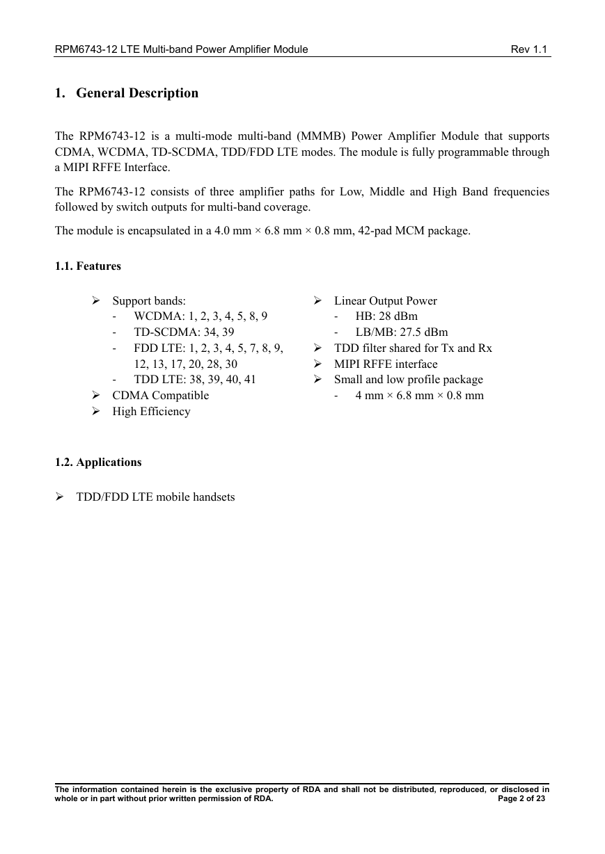
The RPM6743-12 is a multi-mode multi-band (MMMB) Power Amplifier Module that supports
CDMA, WCDMA, TD-SCDMA, TDD/FDD LTE modes. The module is fully programmable through
a MIPI RFFE Interface.
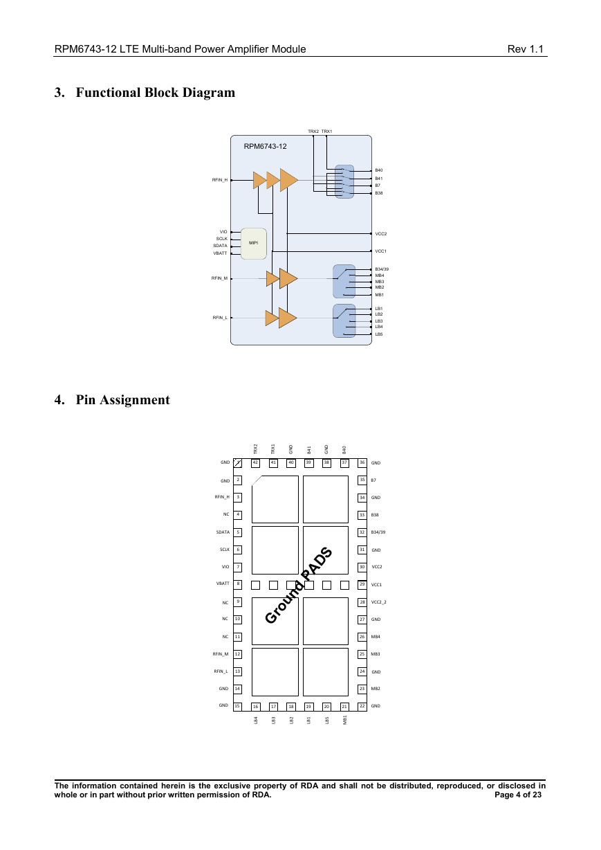
The RPM6743-12 consists of three amplifier paths for Low, Middle and High Band frequencies
followed by switch outputs for multi-band coverage.
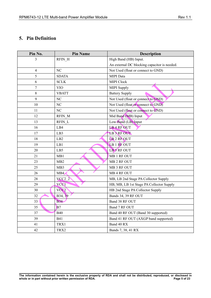
The module is encapsulated in a 4.0 mm × 6.8 mm × 0.8 mm, 42-pad MCM package.
1.1. Features
Support bands:
‐ WCDMA: 1, 2, 3, 4, 5, 8, 9
‐ TD-SCDMA: 34, 39
‐
FDD LTE: 1, 2, 3, 4, 5, 7, 8, 9,
12, 13, 17, 20, 28, 30
‐ TDD LTE: 38, 39, 40, 41
CDMA Compatible
High Efficiency
Linear Output Power
‐ HB: 28 dBm
‐ LB/MB: 27.5 dBm
TDD filter shared for Tx and Rx
MIPI RFFE interface
Small and low profile package
4 mm × 6.8 mm × 0.8 mm
‐
1.2. Applications
TDD/FDD LTE mobile handsets
______________
The information contained herein is the exclusive property of RDA and shall not be distributed, reproduced, or disclosed in
whole or in part without prior written permission of RDA. Page 2 of 23
�
RPM6743-12 LTE Multi-band Power Amplifier Module Rev 1.1
2. Table of Contents
1. General Description ...................................................................................................................................................... 2
1.1.
Features ................................................................................................................................................................ 2
1.2. Applications ......................................................................................................................................................... 2
2. Table of Contents .......................................................................................................................................................... 3
3. Functional Block Diagram ........................................................................................................................................... 4
4. Pin Assignment ............................................................................................................................................................. 4
5. Pin Definition ............................................................................................................................................................... 5
6. Absolute Maximum Ratings ......................................................................................................................................... 6
7. Recommended Operating Conditions ........................................................................................................................... 6
8. MIPI RFFE INFORMATION ....................................................................................................................................... 7
9. Electrical Specifications ............................................................................................................................................. 10
10. Evaluation Board Schematic ...................................................................................................................................... 17
11. Evaluation Board Layout ............................................................................................................................................ 18
12. Package Dimensions ................................................................................................................................................... 19
13. Suggested PCB Design ............................................................................................................................................... 20
14. Recommended Reflow Profile ................................................................................................................................... 21
15. RoHS Compliant ........................................................................................................................................................ 22
16. ESD Precautions ......................................................................................................................................................... 22
17. Change List ................................................................................................................................................................ 23
18. Disclaimer .................................................................................................................................................................. 23
______________
The information contained herein is the exclusive property of RDA and shall not be distributed, reproduced, or disclosed in
whole or in part without prior written permission of RDA. Page 3 of 23
�
RPM6743-12 LTE Multi-band Power Amplifier Module Rev 1.1
3. Functional Block Diagram
TRX2
TRX1
RPM6743-12
RFIN_H
VIO
SCLK
SDATA
VBATT
RFIN_M
RFIN_L
MIPI
4. Pin Assignment
B40
B41
B7
B38
VCC2
VCC1
B34/39
MB4
MB3
MB2
MB1
LB1
LB2
LB3
LB4
LB5
36
GND
35
B7
34
GND
33
B38
32
B34/39
31
GND
30
VCC2
27
GND
26
MB4
25
MB3
24
GND
23
MB2
22
GND
2
X
R
T
42
1
X
R
T
41
D
N
G
40
1
4
B
39
D
N
G
38
0
4
B
37
16
4
B
L
17
3
B
L
18
2
B
L
19
1
B
L
20
5
B
L
21
1
B
M
GND
GND
RFIN_H
NC
SDATA
SCLK
VIO
VBATT
NC
1
2
3
4
5
6
7
8
1
9
NC
10
NC
11
RFIN_M
12
RFIN_L
13
GND
14
GND
15
28
27
Ground PADS
24
26
25
23
29
22
VCC1
28
VCC2_2
______________
The information contained herein is the exclusive property of RDA and shall not be distributed, reproduced, or disclosed in
whole or in part without prior written permission of RDA. Page 4 of 23
�
RPM6743-12 LTE Multi-band Power Amplifier Module Rev 1.1
5. Pin Definition
Pin No.
Pin Name
Description
RFIN_H
NC
SDATA
SCLK
VIO
VBATT
NC
NC
NC
RFIN_M
RFIN_L
LB4
LB3
LB2
LB1
LB5
MB1
MB2
MB3
MB4
VCC2_2
VCC1
VCC2
B34, 39
B38
B7
B40
B41
TRX1
TRX2
3
4
5
6
7
8
9
10
11
12
13
16
17
18
19
20
21
23
25
26
28
29
30
32
33
35
37
39
41
42
High Band (HB) Input.
An external DC blocking capacitor is needed.
Not Used (float or connect to GND)
MIPI Data
MIPI Clock
MIPI Supply
Battery Supply
Not Used (float or connect to GND)
Not Used (float or connect to GND)
Not Used (float or connect to GND)
Mid Band (MB) Input
Low Band (LB) Input
LB 4 RF OUT
LB 3 RF OUT
LB 2 RF OUT
LB 1 RF OUT
LB 5 RF OUT
MB 1 RF OUT
MB 2 RF OUT
MB 3 RF OUT
MB 4 RF OUT
MB, LB 2nd Stage PA Collector Supply
HB, MB, LB 1st Stage PA Collector Supply
HB 2nd Stage PA Collector Supply
Bands 34, 39 RF OUT
Band 38 RF OUT
Band 7 RF OUT
Band 40 RF OUT (Band 30 supported)
Band 41 RF OUT (AXGP band supported)
Band 40 RX
Bands 7, 38, 41 RX
______________
The information contained herein is the exclusive property of RDA and shall not be distributed, reproduced, or disclosed in
whole or in part without prior written permission of RDA. Page 5 of 23
�
RPM6743-12 LTE Multi-band Power Amplifier Module Rev 1.1
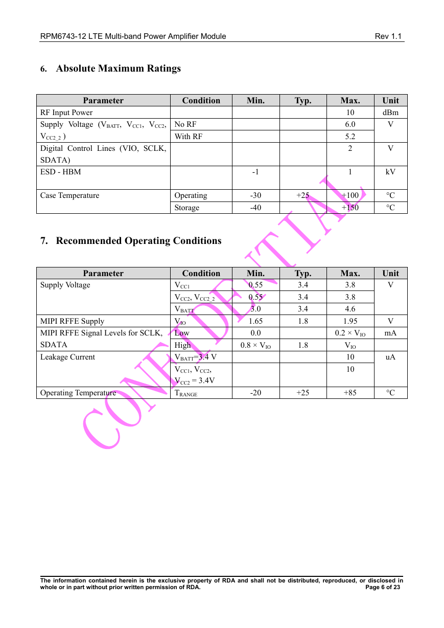
6. Absolute Maximum Ratings
Parameter
Condition
Min.
Typ.
RF Input Power
Supply Voltage (VBATT, VCC1, VCC2,
VCC2_2 )
Digital Control Lines (VIO, SCLK,
SDATA)
ESD - HBM
Case Temperature
No RF
With RF
Operating
Storage
-1
-30
-40
7. Recommended Operating Conditions
Parameter
Supply Voltage
MIPI RFFE Supply
MIPI RFFE Signal Levels for SCLK,
SDATA
Leakage Current
Operating Temperature
Condition
VCC1
VCC2, VCC2_2
VBATT
VIO
Low
High
VBATT=3.4 V
VCC1, VCC2,
VCC2 = 3.4V
TRANGE
Min.
0.55
0.55
3.0
1.65
0.0
0.8 × VIO
-20
+25
Typ.
3.4
3.4
3.4
1.8
1.8
+25
Max.
10
6.0
5.2
2
1
+100
+150
Max.
3.8
3.8
4.6
1.95
0.2 × VIO
VIO
10
10
+85
Unit
dBm
V
V
kV
°C
°C
Unit
V
V
mA
uA
°C
______________
The information contained herein is the exclusive property of RDA and shall not be distributed, reproduced, or disclosed in
whole or in part without prior written permission of RDA. Page 6 of 23
�
RPM6743-12 LTE Multi-band Power Amplifier Module Rev 1.1
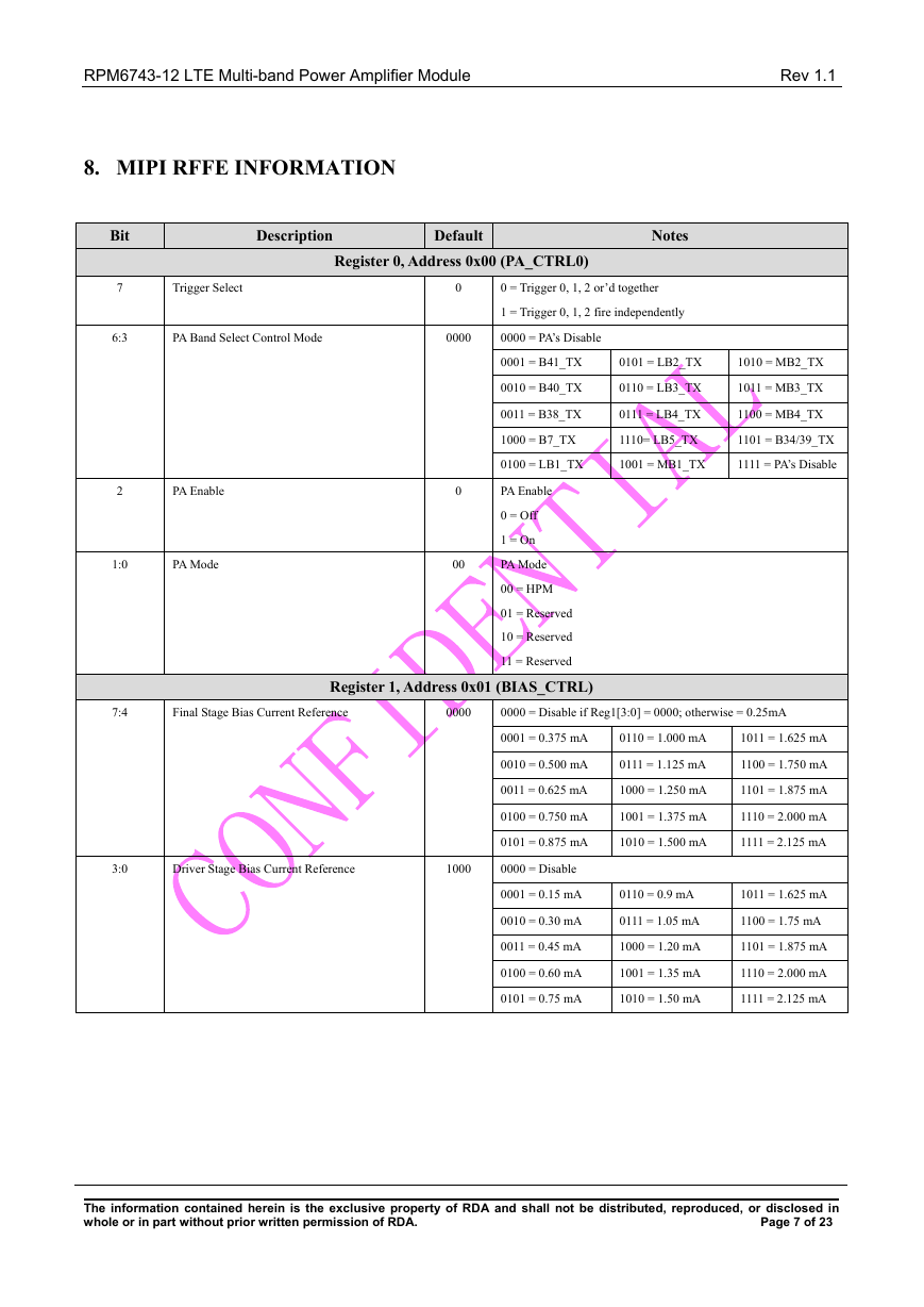
8. MIPI RFFE INFORMATION
Bit
Description
Default
Notes
Register 0, Address 0x00 (PA_CTRL0)
7
Trigger Select
0
0 = Trigger 0, 1, 2 or’d together
1 = Trigger 0, 1, 2 fire independently
6:3
PA Band Select Control Mode
0000
0000 = PA’s Disable
0001 = B41_TX
0101 = LB2_TX
1010 = MB2_TX
0010 = B40_TX
0110 = LB3_TX
1011 = MB3_TX
0011 = B38_TX
0111 = LB4_TX
1100 = MB4_TX
1000 = B7_TX
1110= LB5_TX
1101 = B34/39_TX
0100 = LB1_TX
1001 = MB1_TX
1111 = PA’s Disable
2
PA Enable
1:0
PA Mode
0
00
PA Enable
0 = Off
1 = On
PA Mode
00 = HPM
01 = Reserved
10 = Reserved
11 = Reserved
7:4
Final Stage Bias Current Reference
0000
0000 = Disable if Reg1[3:0] = 0000; otherwise = 0.25mA
Register 1, Address 0x01 (BIAS_CTRL)
0001 = 0.375 mA
0110 = 1.000 mA
1011 = 1.625 mA
0010 = 0.500 mA
0111 = 1.125 mA
1100 = 1.750 mA
0011 = 0.625 mA
1000 = 1.250 mA
1101 = 1.875 mA
0100 = 0.750 mA
1001 = 1.375 mA
1110 = 2.000 mA
0101 = 0.875 mA
1010 = 1.500 mA
1111 = 2.125 mA
3:0
Driver Stage Bias Current Reference
1000
0000 = Disable
0001 = 0.15 mA
0110 = 0.9 mA
1011 = 1.625 mA
0010 = 0.30 mA
0111 = 1.05 mA
1100 = 1.75 mA
0011 = 0.45 mA
1000 = 1.20 mA
1101 = 1.875 mA
0100 = 0.60 mA
1001 = 1.35 mA
1110 = 2.000 mA
0101 = 0.75 mA
1010 = 1.50 mA
1111 = 2.125 mA
______________
The information contained herein is the exclusive property of RDA and shall not be distributed, reproduced, or disclosed in
whole or in part without prior written permission of RDA. Page 7 of 23
�
RPM6743-12 LTE Multi-band Power Amplifier Module Rev 1.1
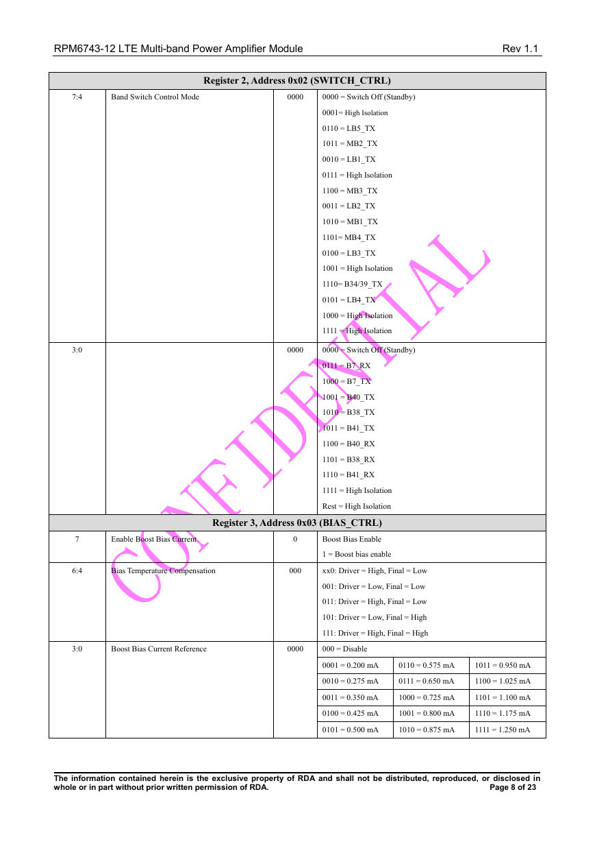
Register 2, Address 0x02 (SWITCH_CTRL)
7:4
Band Switch Control Mode
0000
3:0
0000
0000 = Switch Off (Standby)
0001= High Isolation
0110 = LB5_TX
1011 = MB2_TX
0010 = LB1_TX
0111 = High Isolation
1100 = MB3_TX
0011 = LB2_TX
1010 = MB1_TX
1101= MB4_TX
0100 = LB3_TX
1001 = High Isolation
1110= B34/39_TX
0101 = LB4_TX
1000 = High Isolation
1111 = High Isolation
0000 = Switch Off (Standby)
0111 = B7_RX
1000 = B7_TX
1001 = B40_TX
1010 = B38_TX
1011 = B41_TX
1100 = B40_RX
1101 = B38_RX
1110 = B41_RX
1111 = High Isolation
Rest = High Isolation
7
Enable Boost Bias Current
Register 3, Address 0x03 (BIAS_CTRL)
Boost Bias Enable
1 = Boost bias enable
0
6:4
Bias Temperature Compensation
000
xx0: Driver = High, Final = Low
001: Driver = Low, Final = Low
011: Driver = High, Final = Low
101: Driver = Low, Final = High
111: Driver = High, Final = High
3:0
Boost Bias Current Reference
0000
000 = Disable
0001 = 0.200 mA
0110 = 0.575 mA
1011 = 0.950 mA
0010 = 0.275 mA
0111 = 0.650 mA
1100 = 1.025 mA
0011 = 0.350 mA
1000 = 0.725 mA
1101 = 1.100 mA
0100 = 0.425 mA
1001 = 0.800 mA
1110 = 1.175 mA
0101 = 0.500 mA
1010 = 0.875 mA
1111 = 1.250 mA
______________
The information contained herein is the exclusive property of RDA and shall not be distributed, reproduced, or disclosed in
whole or in part without prior written permission of RDA. Page 8 of 23
�



 2023年江西萍乡中考道德与法治真题及答案.doc
 2012年重庆南川中考生物真题及答案.doc
 2013年江西师范大学地理学综合及文艺理论基础考研真题.doc
 2020年四川甘孜小升初语文真题及答案I卷.doc
 2020年注册岩土工程师专业基础考试真题及答案.doc
 2023-2024学年福建省厦门市九年级上学期数学月考试题及答案.doc
 2021-2022学年辽宁省沈阳市大东区九年级上学期语文期末试题及答案.doc
 2022-2023学年北京东城区初三第一学期物理期末试卷及答案.doc
 2018上半年江西教师资格初中地理学科知识与教学能力真题及答案.doc
 2012年河北国家公务员申论考试真题及答案-省级.doc
 2020-2021学年江苏省扬州市江都区邵樊片九年级上学期数学第一次质量检测试题及答案.doc
 2022下半年黑龙江教师资格证中学综合素质真题及答案.doc