9. Flow Chart of Troubleshooting
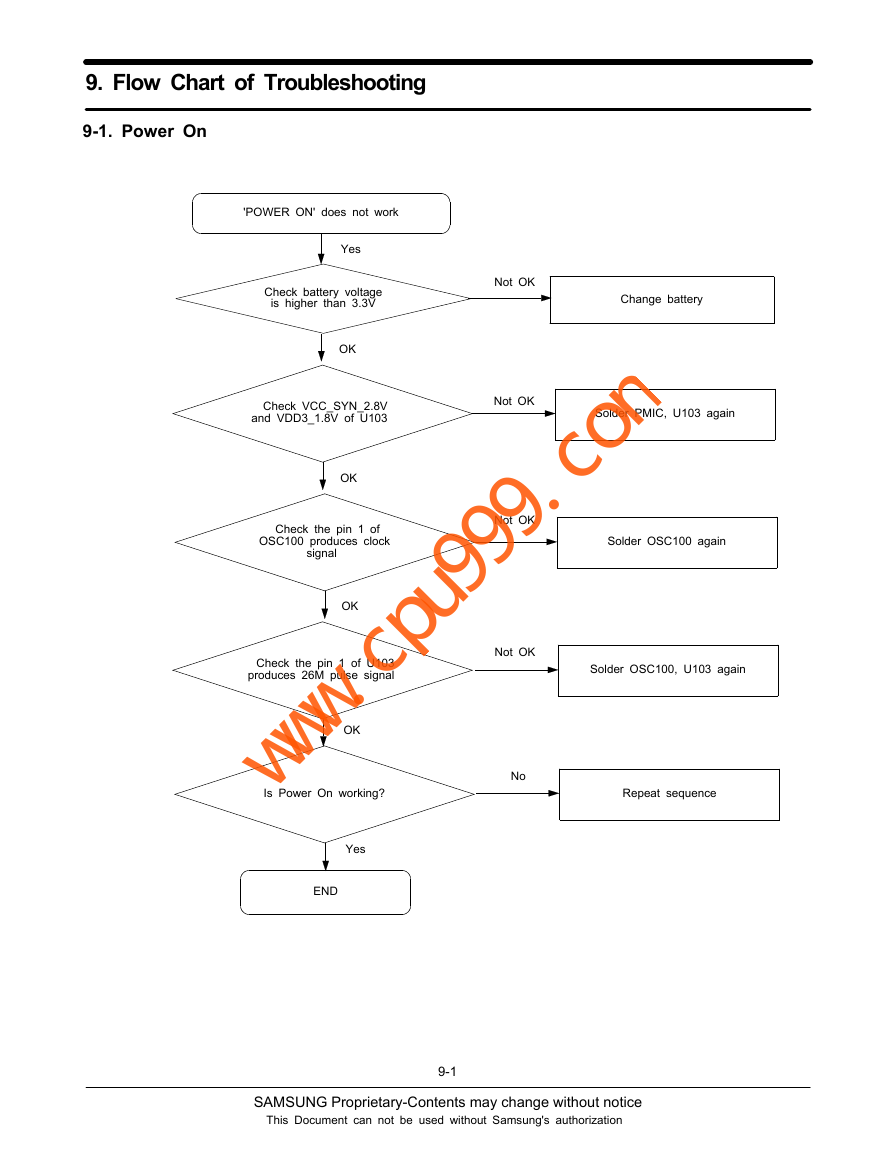
9-1. Power On
'POWER ON' does not work
Yes
Check battery voltage
is higher than 3.3V
OK
Not OK
Change battery
Check VCC_SYN_2.8V
and VDD3_1.8V of U103
Not OK
Solder PMIC, U103 again
OK
Check the pin 1 of
OSC100 produces clock
signal
OK
Check the pin 1 of U103
produces 26M pulse signal
OK
Solder OSC100 again
Solder OSC100, U103 again
Not OK
Not OK
No
Is Power On working?
Repeat sequence
Yes
END
9-1
SAMSUNG Proprietary-Contents may change without notice
This Document can not be used without Samsung's authorization
www.cpu999.com�
Flow Chart of Troubleshooting
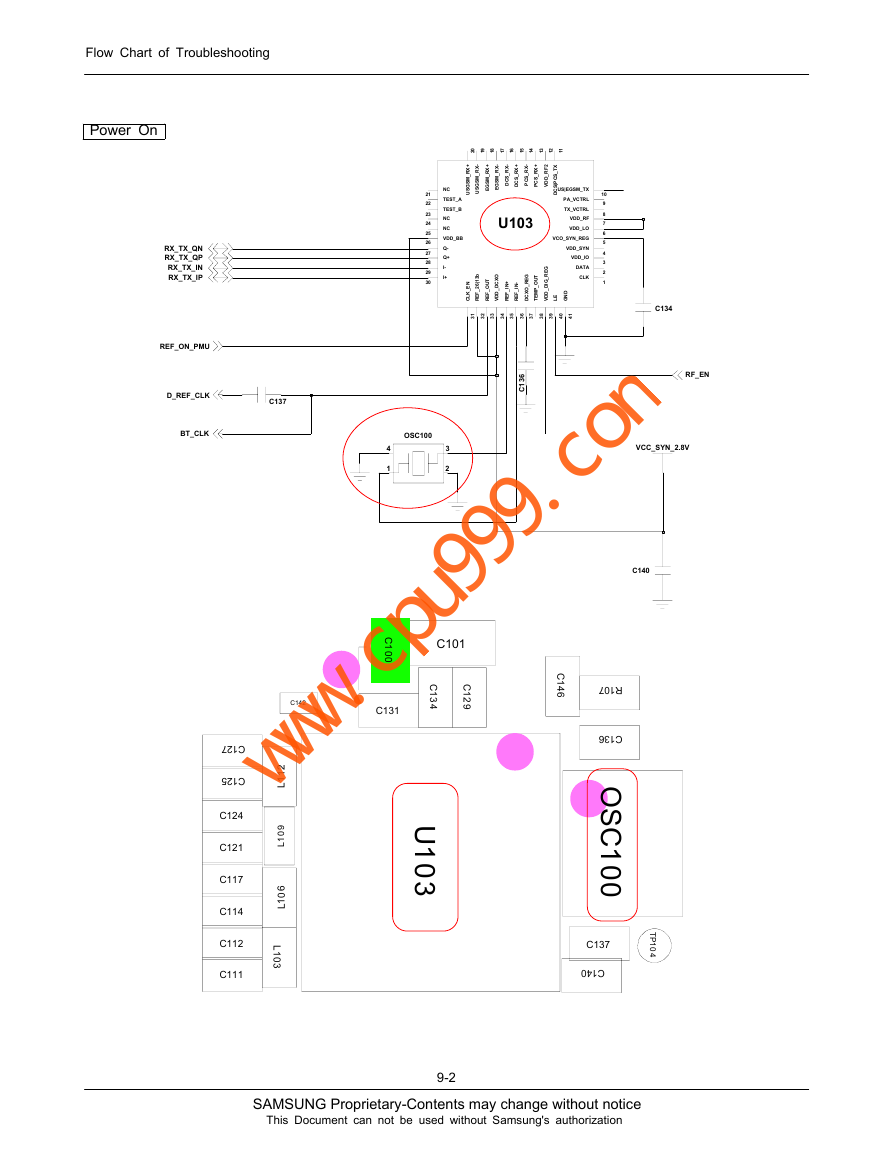
Power On
0
2
9
1
8
1
7
1
6
1
5
1
4
1
3
1
2
1
1
1
RX_TX_QN
RX_TX_QP
RX_TX_IN
RX_TX_IP
REF_ON_PMU
D_REF_CLK
BT_CLK
NC
TEST_A
TEST_B
NC
NC
VDD_BB
Q-
Q+
I-
I+
21
22
23
24
25
26
27
28
29
30
+
X
R
_
M
S
G
S
U
-
X
R
_
M
S
G
S
U
+
X
R
_
M
S
G
E
-
X
R
_
M
S
G
E
-
X
R
_
S
C
D
+
X
R
_
S
C
D
-
X
R
_
S
C
P
+
X
R
_
S
C
P
2
F
R
_
D
D
V
U103
b
3
1
|
6
2
_
F
E
R
O
X
C
D
_
D
D
V
T
U
O
_
F
E
R
N
E
_
K
L
C
G
E
R
_
O
X
C
D
T
U
O
_
P
M
E
T
I
+
N
_
F
E
R
-
I
N
_
F
E
R
G
E
R
_
G
D
_
D
D
V
I
X
T
_
S
C
P
S
C
D
|
US|EGSM_TX
PA_VCTRL
TX_VCTRL
VDD_RF
VDD_LO
VCO_SYN_REG
VDD_SYN
VDD_IO
DATA
CLK
10
9
8
7
6
5
4
3
2
1
D
N
G
E
L
C134
1
3
2
3
3
3
4
3
5
3
6
3
7
3
8
3
9
3
0
4
1
4
6
3
1
C
RF_EN
C137
OSC100
3
2
4
1
C142
2
1
1
L
9
0
1
L
6
0
1
L
L
1
0
3
C127
C125
C124
C121
C117
C114
C112
C111
C
1
0
0
C131
C101
C
1
3
4
C
1
2
9
C
1
4
6
U
1
0
3
9-2
VCC_SYN_2.8V
C140
R107
C136
O
S
C
1
0
0
T
P
1
0
4
C137
C140
SAMSUNG Proprietary-Contents may change without notice
This Document can not be used without Samsung's authorization
www.cpu999.com�
Flow Chart of Troubleshooting
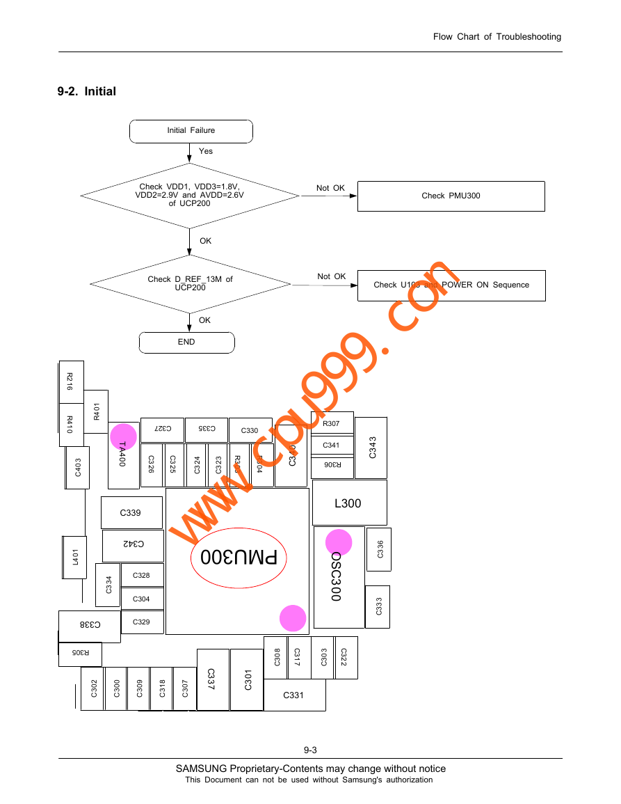
9-2. Initial
Initial Failure
Yes
Check VDD1, VDD3=1.8V,
VDD2=2.9V and AVDD=2.6V
of UCP200
Not OK
Check PMU300
OK
Check D_REF_13M of
UCP200
Not OK
Check U103 and POWER ON Sequence
OK
END
1
0
4
R
R
2
1
6
R
4
1
0
3
0
4
C
1
0
4
L
T
A
4
0
0
C339
C342
4
3
3
C
C328
C304
C329
C338
R305
C327
C335
C330
C
3
2
6
C
4
3
2
2
3
C5
3
2
3
C
R
3
0
3
R
3
0
4
R307
C341
R306
3
4
3
C
0
4
3
C
PMU300
L300
O
S
C
3
0
0
6
3
3
C
3
3
3
C
2
0
3
C
0
0
3
C
9
0
3
C
8
1
3
C
7
0
3
C
C
3
3
7
1
0
3
C
8
0
3
C
C
3
1
7
3
0
3
C
C
3
2
2
C331
9-3
SAMSUNG Proprietary-Contents may change without notice
This Document can not be used without Samsung's authorization
www.cpu999.com�
Flow Chart of Troubleshooting
VDD_TSP_3.0V
AVDD_HFA_2.6V
MOT_3.3V
VDD_IO_HIGH_2.9V
VDD_USB_3.3V
C300
C302
C304
C308
C317
MES_BATT
R300
C319
R302
VBAT
C320
S
U
B
V
+
1
1
E
2
1
D
9
E
8
D
1
C
2
B
2
D
9
A
3
A
1
E
5
C
5
A
7
A
6
B
1
1
C
1
1
A
M2
C3
B4
B10
B8
K6
K12
L5
M10
J5
H6
J7
H8
K8
L9
H12
L11
F12
F10
H2
J1
C9
E5
G9
J9
V_EXT_CHARGE
C323
C325
C324
C326
C327
AMP_SPK_P
AMP_SPK_N
EAR1_M
EAR2_M
SPK_N
SPK_P
C333
OSC300
2
1
REF_ON_PMU
PWREN2
TP323
C337
C338
C339
C340
C336
C342
IN1
IN2
IN3
IN4
IN5
IN6
IN7
IN8
IN9
INA1
INA2
INB1
INB2
C1N
C1P
OUTN
OUTP
CHGIN
CHGINB
XIN
XOUT
PWREN1
PWREN2
TEST1
TEST2
T
T
A
B
B
T
T
A
B
S
T
T
A
B
D
D
V
1
D
D
D
V
2
D
D
D
V
3
D
D
D
V
4
D
D
D
V
5
D
D
D
V
6
D
D
D
V
O
D
D
V
C
H
D
D
V
C
L
D
D
V
P
L
I
S
U
B
V
D
D
V
1
F
R
2
D
D
V
F
R
REC1B G3
REC2B G7
HPL M4
L3
HPR
F2
MICBIAS
RXINN H10
RXINP K10
F4
SIMOFFB
SIMVCC C7
USBLDO B12
VL D10
VBIAS K4
VISA G1
E3
VSAVE
CLK32K H4
IRQB D4
E7
SCL
D6
SDA
L1
LX
J3
FB
F8
REFBP
F6
ONKEYB
RESETB G5
C
N
C
N
1
2
C335
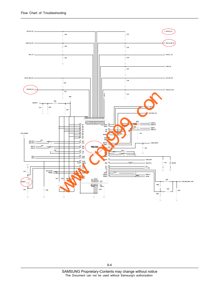
PMU300
D
N
G
A
D
N
G
1
D
N
G
P
2
D
N
G
P
3
D
N
G
P
S
S
V
6
M
1
1
G
2
K
8
M
1
1
J
7
L
C301
C303
C305
C307
C309
C318
VDD_SD_3.3V
VDD_IO_LOW_1.8V
VDD_PLL_1.2V
AVDD_2.6V
VCC_SYN_2.8V
VDD_RX_TX_2.8V
R303
R304
R305
C322
C321
AUX_ON
JACK_IN
MIC_BIAS_2.15V
EARSPK_L
EARSPK_R
SIMOFFn
SIMVCC_M
+VBUS_DETECT
C329
C330
C328
C331
TP_PMU_INT_M
32KHz_DIGIT
PMU_INT_M
SCL
SDA
C332
BAT300
C334
TP324
ONKEY_N
RSTON
VDD_GSM_CORE_1.275V
L300
C341
C343
R306
R307
9-4
SAMSUNG Proprietary-Contents may change without notice
This Document can not be used without Samsung's authorization
www.cpu999.com�
9-3. SIM Part
"Insert SIM" is displayed on the LCD
The voltage is 3.0V
at the pin#1 SIM300,
Pin#11 CD400
Yes
Is there any signal pin
#2,3,4 of SIM300
Pin#13,15,16 CD400 ?
Yes
Check the SIM Card
END
SIM_VCC_1
SIM_VCC_1
R203
SIM_IO_1
SIM200
1
2
3
6 6
55
4 4
G G
7
8 9
G G
10
1
2
3
SIM_RST_1
SIM_CLK_1
C214
5
0
0
1
C215
C216
Flow Chart of Troubleshooting
No
No
Check U200,U210,R200,R209
Check U200, PMU300
VDD_USB_3.3V
R200
SIMVCC_S
C202
SIM_VCC_1
SIMVCC_M
SIMRST_S
SIM_RST_1
SIMRST_M
14
16
15
A
M
O
C
A
O
N
C
C
V
13
D
C
N
1
2
3
4
NCA
A-B_IN
NOB
COMB
U200
12
11
10
COMD
NOD
C-D_IN
NCC 9
B
C
N
D
N
G
C
O
N
C
M
O
C
5
6
7
8
SIMIO_M
SIM_IO_1
SIMIO_S
SIM_SEL
SIMCLK_M
SIM_CLK_1
SIMCLK_S
9-5
SAMSUNG Proprietary-Contents may change without notice
This Document can not be used without Samsung's authorization
www.cpu999.com�
Flow Chart of Troubleshooting
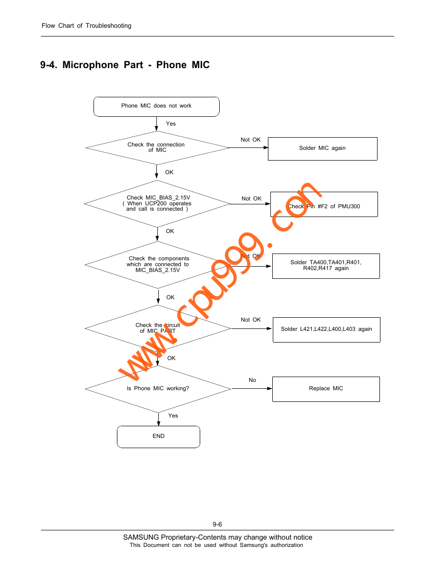
9-4. Microphone Part - Phone MIC
Phone MIC does not work
Yes
Check the connection
of MIC
OK
Check MIC_BIAS_2.15V
( When UCP200 operates
is connected )
and call
OK
Check the components
which are connected to
MIC_BIAS_2.15V
OK
Check the circuit
of MIC PART
OK
Solder MIC again
Check Pin #F2 of PMU300
Solder TA400,TA401,R401,
R402,R417 again
Solder L421,L422,L400,L403 again
Not OK
Not OK
Not OK
Not OK
No
Is Phone MIC working?
Replace MIC
Yes
END
9-6
SAMSUNG Proprietary-Contents may change without notice
This Document can not be used without Samsung's authorization
www.cpu999.com�
Flow Chart of Troubleshooting
L400
C405
C406
L403
MIC_IN_P
MIC_IN_N
C407
R406
L401
R431
C401
C408
C413
MIC_P_M
MIC_N_M
MIC400
11
22
L421
L422
ZD400
ZD401
MIC_BIAS_2.15V
TA400
R401
MIC_SEL_P_M
MIC_SEL_N_M
C403
C411
R410
MIC_BIAS_2.15V
TA401
R402
MIC_SEL_P_S
MIC_SEL_N_S
R407
C409
L402
R432
C404
C412
R411
C402
MIC_P_S
C410
MIC_N_S
C414
9-7
SAMSUNG Proprietary-Contents may change without notice
This Document can not be used without Samsung's authorization
www.cpu999.com�
Flow Chart of Troubleshooting
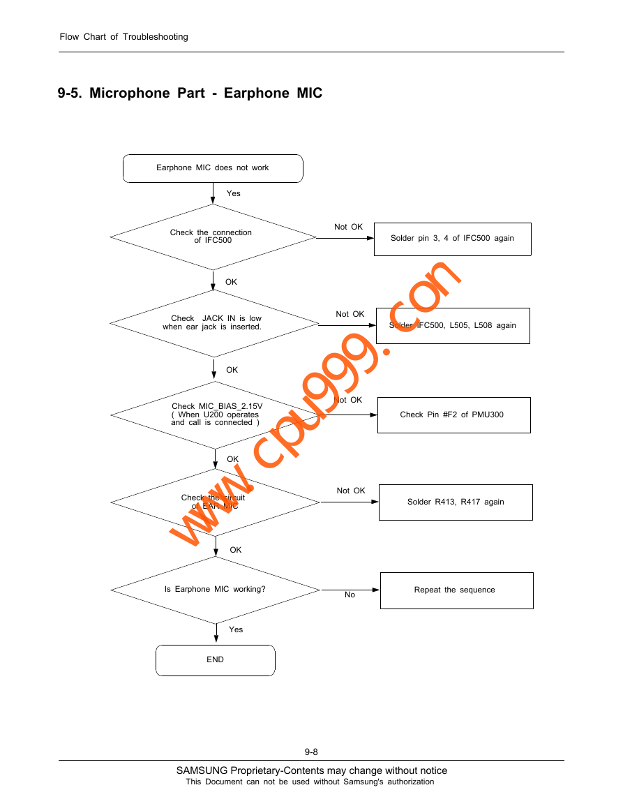
9-5. Microphone Part - Earphone MIC
Earphone MIC does not work
Yes
Check the connection
of IFC500
Not OK
Solder pin 3, 4 of IFC500 again
OK
Check
JACK IN is low
when ear jack is inserted.
Not OK
Solder IFC500, L505, L508 again
OK
Check MIC_BIAS_2.15V
( When U200 operates
and call
is connected )
OK
Check the circuit
of EAR MIC
OK
Not OK
Check Pin #F2 of PMU300
Not OK
Solder R413, R417 again
Is Earphone MIC working?
No
Repeat the sequence
Yes
END
9-8
SAMSUNG Proprietary-Contents may change without notice
This Document can not be used without Samsung's authorization
www.cpu999.com�



 2023年江西萍乡中考道德与法治真题及答案.doc
 2012年重庆南川中考生物真题及答案.doc
 2013年江西师范大学地理学综合及文艺理论基础考研真题.doc
 2020年四川甘孜小升初语文真题及答案I卷.doc
 2020年注册岩土工程师专业基础考试真题及答案.doc
 2023-2024学年福建省厦门市九年级上学期数学月考试题及答案.doc
 2021-2022学年辽宁省沈阳市大东区九年级上学期语文期末试题及答案.doc
 2022-2023学年北京东城区初三第一学期物理期末试卷及答案.doc
 2018上半年江西教师资格初中地理学科知识与教学能力真题及答案.doc
 2012年河北国家公务员申论考试真题及答案-省级.doc
 2020-2021学年江苏省扬州市江都区邵樊片九年级上学期数学第一次质量检测试题及答案.doc
 2022下半年黑龙江教师资格证中学综合素质真题及答案.doc