Frequency Diverse Array Receiver Architectures
A thesis submitted in partial fulfillment
of the requirements for the degree of
Master of Science in Engineering
by
Aaron M. Jones
Department of Electrical Engineering and Computer Science
B.S. Engineering Physics, Wright State University, 2007
2011
Wright State University
�
Wright State University
SCHOOL OF GRADUATE STUDIES
I HEREBY RECOMMEND THAT THE THESIS PREPARED UNDER MY SUPER-
VISION BY Aaron M. Jones ENTITLED Frequency Diverse Array Receiver Architectures
BE ACCEPTED IN PARTIAL FULFILLMENT OF THE REQUIREMENTS FOR THE
DEGREE OF Master of Science in Engineering.
November 18, 2011
Brian D. Rigling, Ph.D.
Thesis Director
Kefu Xue, Ph.D.
Department Chair of Electrical Engineering
Committee on
Final Examination
Brian D. Rigling, Ph.D.
Fred Garber, Ph.D.
Douglas T. Petkie, Ph.D.
Andrew Hsu, Ph.D.
Dean, Graduate School
�
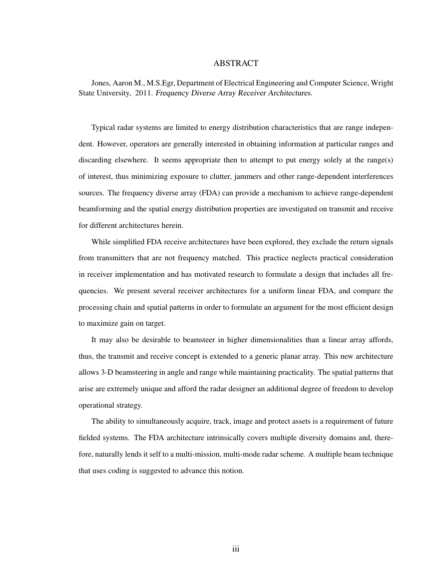
ABSTRACT
Jones, Aaron M., M.S.Egr, Department of Electrical Engineering and Computer Science, Wright
State University, 2011. Frequency Diverse Array Receiver Architectures.
Typical radar systems are limited to energy distribution characteristics that are range indepen-
dent. However, operators are generally interested in obtaining information at particular ranges and
discarding elsewhere.
It seems appropriate then to attempt to put energy solely at the range(s)
of interest, thus minimizing exposure to clutter, jammers and other range-dependent interferences
sources. The frequency diverse array (FDA) can provide a mechanism to achieve range-dependent
beamforming and the spatial energy distribution properties are investigated on transmit and receive
for different architectures herein.
While simplified FDA receive architectures have been explored, they exclude the return signals
from transmitters that are not frequency matched. This practice neglects practical consideration
in receiver implementation and has motivated research to formulate a design that includes all fre-
quencies. We present several receiver architectures for a uniform linear FDA, and compare the
processing chain and spatial patterns in order to formulate an argument for the most efficient design
to maximize gain on target.
It may also be desirable to beamsteer in higher dimensionalities than a linear array affords,
thus, the transmit and receive concept is extended to a generic planar array. This new architecture
allows 3-D beamsteering in angle and range while maintaining practicality. The spatial patterns that
arise are extremely unique and afford the radar designer an additional degree of freedom to develop
operational strategy.
The ability to simultaneously acquire, track, image and protect assets is a requirement of future
fielded systems. The FDA architecture intrinsically covers multiple diversity domains and, there-
fore, naturally lends it self to a multi-mission, multi-mode radar scheme. A multiple beam technique
that uses coding is suggested to advance this notion.
iii
�
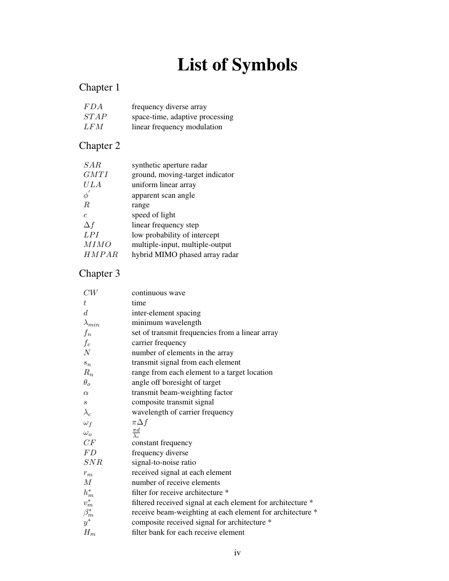
List of Symbols
Chapter 1
F DA
ST AP
LF M
frequency diverse array
space-time, adaptive processing
linear frequency modulation
Chapter 2
SAR
GM T I
U LA
φ
R
c
∆f
LP I
M IM O
HM P AR
Chapter 3
synthetic aperture radar
ground, moving-target indicator
uniform linear array
apparent scan angle
range
speed of light
linear frequency step
low probability of intercept
multiple-input, multiple-output
hybrid MIMO phased array radar
CW
t
d
λmin
fn
fc
N
sn
Rn
θo
α
s
λc
ωf
ωo
CF
F D
SN R
rm
M
h∗
v∗
β∗
y∗
Hm
m
m
m
continuous wave
time
inter-element spacing
minimum wavelength
set of transmit frequencies from a linear array
carrier frequency
number of elements in the array
transmit signal from each element
range from each element to a target location
angle off boresight of target
transmit beam-weighting factor
composite transmit signal
wavelength of carrier frequency
π∆f
πd
λc
constant frequency
frequency diverse
signal-to-noise ratio
received signal at each element
number of receive elements
filter for receive architecture *
filtered received signal at each element for architecture *
receive beam-weighting at each element for architecture *
composite received signal for architecture *
filter bank for each receive element
iv
�
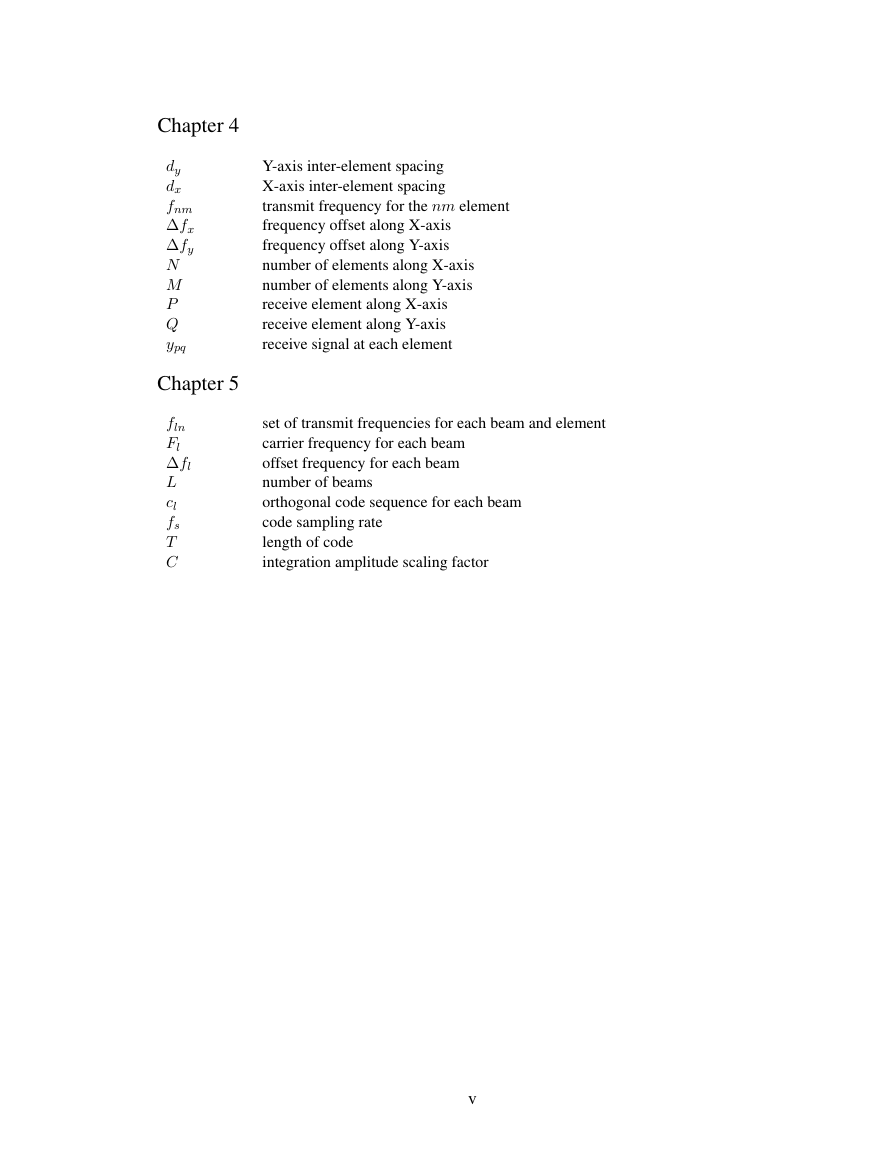
Chapter 4
dy
dx
fnm
∆fx
∆fy
N
M
P
Q
ypq
Chapter 5
fln
Fl
∆fl
L
cl
fs
T
C
Y-axis inter-element spacing
X-axis inter-element spacing
transmit frequency for the nm element
frequency offset along X-axis
frequency offset along Y-axis
number of elements along X-axis
number of elements along Y-axis
receive element along X-axis
receive element along Y-axis
receive signal at each element
set of transmit frequencies for each beam and element
carrier frequency for each beam
offset frequency for each beam
number of beams
orthogonal code sequence for each beam
code sampling rate
length of code
integration amplitude scaling factor
v
�
Contents
1
Introduction
1.1 Motivation .
.
1.2 Contribution .
1.3 Organization .
2 Literature Review
.
.
.
.
.
.
.
.
.
.
.
.
.
.
.
. . . . . . . . . . . . . . . . . . . . . . . . . . . . . . . .
. . . . . . . . . . . . . . . . . . . . . . . . . . . . . . . .
. . . . . . . . . . . . . . . . . . . . . . . . . . . . . . . .
2.1 Range Dependent Transmit Spatial Pattern . . . . . . . . . . . . . . . . . . . . . .
2.2 SAR Using a FDA Configuration . . . . . . . . . . . . . . . . . . . . . . . . . . .
2.3 FDA in Conjunction with MIMO Radar
. . . . . . . . . . . . . . . . . . . . . . .
2.4 Spurious Applications . . . . . . . . . . . . . . . . . . . . . . . . . . . . . . . . .
3 Linear Array Receiver Architectures
3.1.1
3.1 FDA Transmit Pattern .
. . . . . . . . . . . . . . . . . . . . . . . . . . . . . . . .
FDA Time Dependency Spatial Pattern . . . . . . . . . . . . . . . . . . .
3.2 FDA Received Signal .
. . . . . . . . . . . . . . . . . . . . . . . . . . . . . . . .
3.3 Receiver Processing Architectures . . . . . . . . . . . . . . . . . . . . . . . . . .
3.3.1 Band-limited, Coherent FDA . . . . . . . . . . . . . . . . . . . . . . . . .
Full-band, Pseudo-coherent FDA . . . . . . . . . . . . . . . . . . . . . .
3.3.2
3.3.3
Full-band, Coherent FDA . . . . . . . . . . . . . . . . . . . . . . . . . .
4 Planar Array Architectures
4.1 Geometry and Scenario . . . . . . . . . . . . . . . . . . . . . . . . . . . . . . . .
4.2 Planar FDA Transmit Pattern . . . . . . . . . . . . . . . . . . . . . . . . . . . . .
4.2.1 Transmit Signal Model . . . . . . . . . . . . . . . . . . . . . . . . . . . .
. . . . . . . . . . . . . . . . . . . .
4.2.2
4.3 Planar FDA Receive Pattern . . . . . . . . . . . . . . . . . . . . . . . . . . . . .
. . . . . . . . . . . . . . . . . . . . . . . . . . . .
Spatial Pattern Snapshots . . . . . . . . . . . . . . . . . . . . . . . . . . .
4.3.1 Receive Signal Model
4.3.2
Planar Array Spatial Pattern Snapshot
5 Multiple Beam Transmit and Receive with Coding
5.1 Geometry and Scenario . . . . . . . . . . . . . . . . . . . . . . . . . . . . . . . .
. . . . . . . . . . . . . . . . . . . . . . .
5.2 Uncoded Transmit and Receive Signals
5.2.1 Transmit Signal Structure
. . . . . . . . . . . . . . . . . . . . . . . . . .
5.2.2 Receive Signal Structure . . . . . . . . . . . . . . . . . . . . . . . . . . .
. . . . . . . . . . . . . . . . . . . . . . . . . . . . . . . . .
5.3 Coding Technique .
.
6 Conclusions and Future Work
vi
1
2
2
3
4
4
5
6
6
8
9
14
14
16
16
17
21
27
28
28
31
33
35
36
39
44
45
46
47
48
53
57
�
Bibliography
58
vii
�
List of Figures
3.1 Example of a linear FDA . . . . . . . . . . . . . . . . . . . . . . . . . . . . . . .
3.2 FDA geometric set-up .
. . . . . . . . . . . . . . . . . . . . . . . . . . . . . . . .
3.3 Transmit pattern comparison of CF and FD arrays . . . . . . . . . . . . . . . . . .
3.4 FDA time dependency examination for positive offset . . . . . . . . . . . . . . . .
3.5 FDA time dependency examination for negative offset . . . . . . . . . . . . . . . .
3.6 Band-limited, coherent FDA architecture beamforming chain . . . . . . . . . . . .
3.7 Composite receive pattern for band-limited, coherent FDA architecture . . . . . . .
3.8 Full-band, pseudo-coherent FDA architecture . . . . . . . . . . . . . . . . . . . .
3.9 Composite receive pattern for full-band, pseudo-coherent FDA architecture . . . .
3.10 Beamforming chain for the full-band, coherent FDA architecture . . . . . . . . . .
3.11 Uniform linear array composite receive pattern for full-band, coherent architecture
. . . .
4.1 Basic geometric set-up for a planar array . . . . . . . . . . . . . . . . . . . . . . .
4.2 Example of planar array with frequency offsets
. . . . . . . . . . . . . . . . . . .
4.3 The 10-dB main beam transmit pattern is shown for a 9 × 9 planar array with (left)
frequency diversity (∆fx = 1 kHz, ∆fy = 10 kHz) and (right) constant frequency
transmit waveforms. .
. . . . . . . . . . . . . . . . . . . . . . . . . . . . .
. . . . . . . . . . . . . . . . . . .
4.4 Transmit spatial pattern from a planar array (1)
. . . . . . . . . . . . . . . . . . .
4.5 Transmit spatial pattern from a planar array (2)
. . . . . . . . . . . . . . . . . . .
4.6 Transmit spatial pattern from a planar array (3)
4.7 Transmit spatial pattern from a planar array (4)
. . . . . . . . . . . . . . . . . . .
4.8 Receive beamforming chain of the planar FDA architecture . . . . . . . . . . . . .
4.9 Planar array receive pattern, global view . . . . . . . . . . . . . . . . . . . . . . .
4.10 Planar array receive pattern, side view . . . . . . . . . . . . . . . . . . . . . . . .
4.11 Planar array receive pattern, top view . . . . . . . . . . . . . . . . . . . . . . . . .
4.12 Composite receive pattern snapshot for a 9 × 9 FDA for 10-dB beamwidth.
. . . .
4.13 Composite receive pattern snapshot for a 9 × 9 FDA for 15-dB beamwidth.
. . . .
4.14 Composite receive pattern snapshot for a 9 × 9 FDA for 20-dB beamwidth.
. . . .
4.15 Composite receive pattern snapshot for a 9 × 9 FDA for 25-dB beamwidth.
. . . .
5.1 Multiple beam scenario and set-up . . . . . . . . . . . . . . . . . . . . . . . . . .
5.2 Transmit multiple beam spatial pattern comparison . . . . . . . . . . . . . . . . .
5.3 Beamforming chain with filter structures for two beams. Components include: filter
banks at each element for each beam with a beamsteering mechanism and power
combiners. .
. . . . . . . . . . . . . . . . . . . . . . . . . . . . . . . . .
5.4 Multiple beam receive patterns with and without crosstalk . . . . . . . . . . . . .
5.5 Multiple beam receive patterns with and with crosstalk . . . . . . . . . . . . . . .
.
.
.
.
.
10
11
13
15
16
18
19
20
22
23
26
29
30
34
34
35
36
37
38
40
41
41
42
42
43
43
45
48
49
51
52
viii
�



 2023年江西萍乡中考道德与法治真题及答案.doc
 2012年重庆南川中考生物真题及答案.doc
 2013年江西师范大学地理学综合及文艺理论基础考研真题.doc
 2020年四川甘孜小升初语文真题及答案I卷.doc
 2020年注册岩土工程师专业基础考试真题及答案.doc
 2023-2024学年福建省厦门市九年级上学期数学月考试题及答案.doc
 2021-2022学年辽宁省沈阳市大东区九年级上学期语文期末试题及答案.doc
 2022-2023学年北京东城区初三第一学期物理期末试卷及答案.doc
 2018上半年江西教师资格初中地理学科知识与教学能力真题及答案.doc
 2012年河北国家公务员申论考试真题及答案-省级.doc
 2020-2021学年江苏省扬州市江都区邵樊片九年级上学期数学第一次质量检测试题及答案.doc
 2022下半年黑龙江教师资格证中学综合素质真题及答案.doc