NT35510
One-chip Driver IC with internal GRAM
for 16.7M colors 480RGB x 864 a-Si TFT LCD
with CPU / RGB / MIPI / MDDI Interface
or without internal CGRAM
for 16.7M colors 480RGB x 1024 a-Si TFT LCD
with RGB Interface
V0.04
Preliminary
Á Љꗬꗬ
7/28/2010
With respect to the information represented in this document, Novatek makes no warranty, expressed or implied, including the warranties of merchantability,
fitness for a particular purpose, non-infringement, or assumes any legal liability or responsibility for the accuracy, completeness, or usefulness of any such
information.
Version 0.04
1
�
PRELIMINARY NT35510
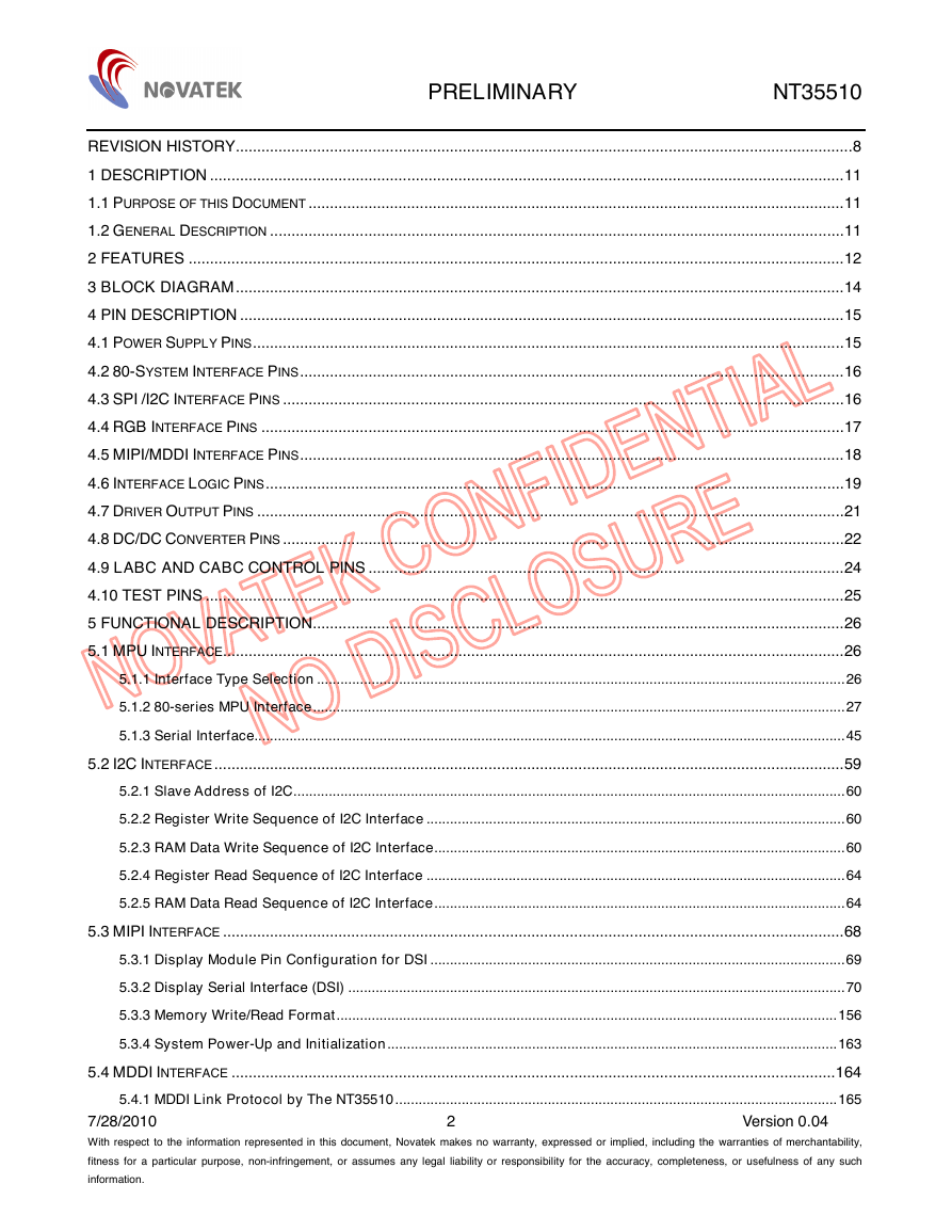
REVISION HISTORY................................................................................................................................................8
1 DESCRIPTION ....................................................................................................................................................11
1.1 PURPOSE OF THIS DOCUMENT .............................................................................................................................11
1.2 GENERAL DESCRIPTION ......................................................................................................................................11
2 FEATURES .........................................................................................................................................................12
3 BLOCK DIAGRAM..............................................................................................................................................14
4 PIN DESCRIPTION .............................................................................................................................................15
4.1 POWER SUPPLY PINS..........................................................................................................................................15
4.2 80-SYSTEM INTERFACE PINS...............................................................................................................................16
4.3 SPI /I2C INTERFACE PINS ...................................................................................................................................16
4.4 RGB INTERFACE PINS ........................................................................................................................................17
4.5 MIPI/MDDI INTERFACE PINS...............................................................................................................................18
4.6 INTERFACE LOGIC PINS.......................................................................................................................................19
4.7 DRIVER OUTPUT PINS .........................................................................................................................................21
4.8 DC/DC CONVERTER PINS ...................................................................................................................................22
4.9 LABC AND CABC CONTROL PINS ...............................................................................................................24
4.10 TEST PINS .....................................................................................................................................................25
5 FUNCTIONAL DESCRIPTION............................................................................................................................26
5.1 MPU INTERFACE.................................................................................................................................................26
5.1.1 Interface Type Selection .......................................................................................................................................26
5.1.2 80-series MPU Interface........................................................................................................................................27
5.1.3 Serial Interface.......................................................................................................................................................45
5.2 I2C INTERFACE...................................................................................................................................................59
5.2.1 Slave Address of I2C.............................................................................................................................................60
5.2.2 Register Write Sequence of I2C Interface ...........................................................................................................60
5.2.3 RAM Data Write Sequence of I2C Interface.........................................................................................................60
5.2.4 Register Read Sequence of I2C Interface ...........................................................................................................64
5.2.5 RAM Data Read Sequence of I2C Interface.........................................................................................................64
5.3 MIPI INTERFACE .................................................................................................................................................68
5.3.1 Display Module Pin Configuration for DSI ..........................................................................................................69
5.3.2 Display Serial Interface (DSI) ...............................................................................................................................70
5.3.3 Memory Write/Read Format................................................................................................................................156
5.3.4 System Power-Up and Initialization...................................................................................................................163
5.4 MDDI INTERFACE .............................................................................................................................................164
5.4.1 MDDI Link Protocol by The NT35510.................................................................................................................165
7/28/2010
With respect to the information represented in this document, Novatek makes no warranty, expressed or implied, including the warranties of merchantability,
fitness for a particular purpose, non-infringement, or assumes any legal liability or responsibility for the accuracy, completeness, or usefulness of any such
information.
Version 0.04
2
�
PRELIMINARY NT35510
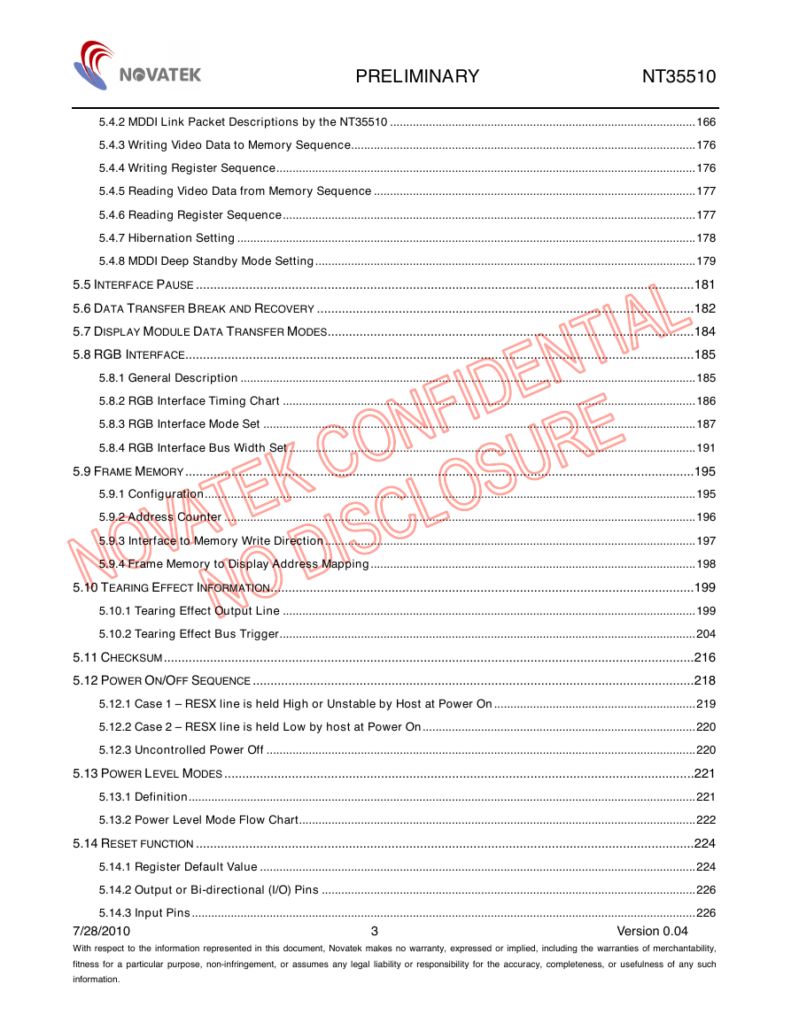
5.4.2 MDDI Link Packet Descriptions by the NT35510 ..............................................................................................166
5.4.3 Writing Video Data to Memory Sequence..........................................................................................................176
5.4.4 Writing Register Sequence.................................................................................................................................176
5.4.5 Reading Video Data from Memory Sequence ...................................................................................................177
5.4.6 Reading Register Sequence...............................................................................................................................177
5.4.7 Hibernation Setting .............................................................................................................................................178
5.4.8 MDDI Deep Standby Mode Setting.....................................................................................................................179
5.5 INTERFACE PAUSE ............................................................................................................................................181
5.6 DATA TRANSFER BREAK AND RECOVERY ..........................................................................................................182
5.7 DISPLAY MODULE DATA TRANSFER MODES.......................................................................................................184
5.8 RGB INTERFACE...............................................................................................................................................185
5.8.1 General Description ............................................................................................................................................185
5.8.2 RGB Interface Timing Chart ...............................................................................................................................186
5.8.3 RGB Interface Mode Set .....................................................................................................................................187
5.8.4 RGB Interface Bus Width Set .............................................................................................................................191
5.9 FRAME MEMORY...............................................................................................................................................195
5.9.1 Configuration.......................................................................................................................................................195
5.9.2 Address Counter .................................................................................................................................................196
5.9.3 Interface to Memory Write Direction..................................................................................................................197
5.9.4 Frame Memory to Display Address Mapping....................................................................................................198
5.10 TEARING EFFECT INFORMATION.......................................................................................................................199
5.10.1 Tearing Effect Output Line ...............................................................................................................................199
5.10.2 Tearing Effect Bus Trigger................................................................................................................................204
5.11 CHECKSUM.....................................................................................................................................................216
5.12 POWER ON/OFF SEQUENCE ............................................................................................................................218
5.12.1 Case 1 – RESX line is held High or Unstable by Host at Power On..............................................................219
5.12.2 Case 2 – RESX line is held Low by host at Power On....................................................................................220
5.12.3 Uncontrolled Power Off ....................................................................................................................................220
5.13 POWER LEVEL MODES ....................................................................................................................................221
5.13.1 Definition............................................................................................................................................................221
5.13.2 Power Level Mode Flow Chart..........................................................................................................................222
5.14 RESET FUNCTION ............................................................................................................................................224
5.14.1 Register Default Value ......................................................................................................................................224
5.14.2 Output or Bi-directional (I/O) Pins ...................................................................................................................226
5.14.3 Input Pins...........................................................................................................................................................226
7/28/2010
With respect to the information represented in this document, Novatek makes no warranty, expressed or implied, including the warranties of merchantability,
fitness for a particular purpose, non-infringement, or assumes any legal liability or responsibility for the accuracy, completeness, or usefulness of any such
information.
Version 0.04
3
�
PRELIMINARY NT35510
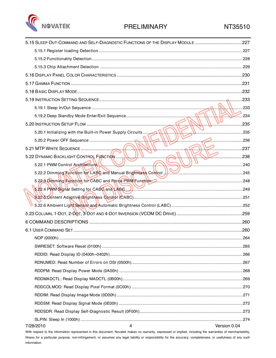
5.15 SLEEP OUT-COMMAND AND SELF-DIAGNOSTIC FUNCTIONS OF THE DISPLAY MODULE ......................................227
5.15.1 Register loading Detection...............................................................................................................................227
5.15.2 Functionality Detection.....................................................................................................................................228
5.15.3 Chip Attachment Detection ..............................................................................................................................229
5.16 DISPLAY PANEL COLOR CHARACTERISTICS .....................................................................................................230
5.17 GAMMA FUNCTION ..........................................................................................................................................231
5.18 BASIC DISPLAY MODE.....................................................................................................................................232
5.19 INSTRUCTION SETTING SEQUENCE...................................................................................................................233
5.19.1 Sleep In/Out Sequence .....................................................................................................................................233
5.19.2 Deep Standby Mode Enter/Exit Sequence.......................................................................................................234
5.20 INSTRUCTION SETUP FLOW .............................................................................................................................235
5.20.1 Initializing with the Built-in Power Supply Circuits........................................................................................235
5.20.2 Power OFF Sequence .......................................................................................................................................236
5.21 MTP WRITE SEQUENCE ..................................................................................................................................237
5.22 DYNAMIC BACKLIGHT CONTROL FUNCTION......................................................................................................238
5.22.1 PWM Control Architecture................................................................................................................................240
5.22.2 Dimming Function for LABC and Manual Brightness Control ......................................................................245
5.22.3 Dimming Function for CABC and Force PWM Function................................................................................248
5.22.4 PWM Signal Setting for CABC and LABC .......................................................................................................249
5.22.5 Content Adaptive Brightness Control (CABC)................................................................................................251
5.22.6 Ambient Light Sensor and Automatic Brightness Control (LABC)...............................................................252
5.23 COLUMN, 1-DOT, 2-DOT, 3-DOT AND 4-DOT INVERSION (VCOM DC DRIVE).....................................................259
6 COMMAND DESCRIPTIONS ...........................................................................................................................260
6.1 USER COMMAND SET........................................................................................................................................260
NOP (0000h)..................................................................................................................................................................264
SWRESET: Software Reset (0100h) ............................................................................................................................265
RDDID: Read Display ID (0400h~0402h).....................................................................................................................266
RDNUMED: Read Number of Errors on DSI (0500h)..................................................................................................267
RDDPM: Read Display Power Mode (0A00h) .............................................................................................................268
RDDMADCTL: Read Display MADCTL (0B00h)..........................................................................................................269
RDDCOLMOD: Read Display Pixel Format (0C00h) ..................................................................................................270
RDDIM: Read Display Image Mode (0D00h) ...............................................................................................................271
RDDSM: Read Display Signal Mode (0E00h) .............................................................................................................272
RDDSDR: Read Display Self-Diagnostic Result (0F00h)...........................................................................................273
SLPIN: Sleep In (1000h) ...............................................................................................................................................274
7/28/2010
With respect to the information represented in this document, Novatek makes no warranty, expressed or implied, including the warranties of merchantability,
fitness for a particular purpose, non-infringement, or assumes any legal liability or responsibility for the accuracy, completeness, or usefulness of any such
information.
Version 0.04
4
�
PRELIMINARY NT35510
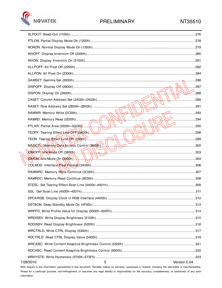
SLPOUT: Sleep Out (1100h).........................................................................................................................................276
PTLON: Partial Display Mode On (1200h) ..................................................................................................................278
NORON: Normal Display Mode On (1300h)................................................................................................................279
INVOFF: Display Inversion Off (2000h).......................................................................................................................280
INVON: Display Inversion On (2100h).........................................................................................................................281
ALLPOFF: All Pixel Off (2200h) ...................................................................................................................................282
ALLPON: All Pixel On (2300h) .....................................................................................................................................284
GAMSET: Gamma Set (2600h).....................................................................................................................................286
DISPOFF: Display Off (2800h) .....................................................................................................................................287
DISPON: Display On (2900h) .......................................................................................................................................288
CASET: Column Address Set (2A00h~2A03h) ...........................................................................................................289
RASET: Row Address Set (2B00h~2B03h).................................................................................................................291
RAMWR: Memory Write (2C00h) .................................................................................................................................293
RAMRD: Memory Read (2E00h) ..................................................................................................................................294
PTLAR: Partial Area (3000h~3003h)............................................................................................................................295
TEOFF: Tearing Effect Line OFF (3400h)....................................................................................................................298
TEON: Tearing Effect Line ON (3500h) .......................................................................................................................299
MADCTL: Memory Data Access Control (3600h).......................................................................................................300
IDMOFF: Idle Mode Off (3800h) ...................................................................................................................................303
IDMON: Idle Mode On (3900h) .....................................................................................................................................304
COLMOD: Interface Pixel Format (3A00h)..................................................................................................................306
RAMWRC: Memory Write Continue (3C00h) ..............................................................................................................307
RAMRDC: Memory Read Continue (3E00h) ...............................................................................................................308
STESL: Set Tearing Effect Scan Line (4400h~4401h)................................................................................................309
GSL: Get Scan Line (4500h~4501h)............................................................................................................................ 311
DPCKRGB: Display Clock in RGB Interface (4A00h) ................................................................................................312
DSTBON: Deep Standby Mode On (4F00h) ................................................................................................................313
WRPFD: Write Profile Value for Display (5000h~500Fh) ...........................................................................................314
WRDISBV: Write Display Brightness (5100h) ............................................................................................................315
RDDISBV: Read Display Brightness (5200h) .............................................................................................................316
WRCTRLD: Write CTRL Display (5300h) ....................................................................................................................317
RDCTRLD: Read CTRL Display Value (5400h)...........................................................................................................319
WRCABC: Write Content Adaptive Brightness Control (5500h) ..............................................................................321
RDCABC: Read Content Adaptive Brightness Control (5600h) ...............................................................................322
WRHYSTE: Write Hysteresis (5700h~573Fh) .............................................................................................................323
7/28/2010
With respect to the information represented in this document, Novatek makes no warranty, expressed or implied, including the warranties of merchantability,
fitness for a particular purpose, non-infringement, or assumes any legal liability or responsibility for the accuracy, completeness, or usefulness of any such
information.
Version 0.04
5
�
PRELIMINARY NT35510
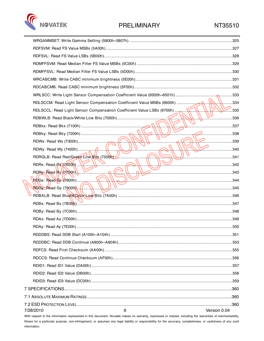
WRGAMMSET: Write Gamma Setting (5800h~5807h) ...............................................................................................325
RDFSVM: Read FS Value MSBs (5A00h) ....................................................................................................................327
RDFSVL: Read FS Value LSBs (5B00h)......................................................................................................................328
RDMFFSVM: Read Median Filter FS Value MSBs (5C00h) ........................................................................................329
RDMFFSVL: Read Median Filter FS Value LSBs (5D00h)..........................................................................................330
WRCABCMB: Write CABC minimum brightness (5E00h).........................................................................................331
RDCABCMB: Read CABC minimum brightness (5F00h) ..........................................................................................332
WRLSCC: Write Light Sensor Compensation Coefficient Value (6500h~6501h) ....................................................333
RDLSCCM: Read Light Sensor Compensation Coefficient Value MSBs (6600h) ...................................................334
RDLSCCL: Read Light Sensor Compensation Coefficient Value LSBs (6700h) .....................................................335
RDBWLB: Read Black/White Low Bits (7000h)..........................................................................................................336
RDBkx: Read Bkx (7100h) ...........................................................................................................................................337
RDBky: Read Bky (7200h) ...........................................................................................................................................338
RDWx: Read Wx (7300h)..............................................................................................................................................339
RDWy: Read Wy (7400h)..............................................................................................................................................340
RDRGLB: Read Red/Green Low Bits (7500h) ............................................................................................................341
RDRx: Read Rx (7600h) ...............................................................................................................................................342
RDRy: Read Ry (7700h) ...............................................................................................................................................343
RDGx: Read Gx (7800h)...............................................................................................................................................344
RDGy: Read Gy (7900h)...............................................................................................................................................345
RDBALB: Read Blue/AColor Low Bits (7A00h) .........................................................................................................346
RDBx: Read Bx (7B00h)...............................................................................................................................................347
RDBy: Read By (7C00h)...............................................................................................................................................348
RDAx: Read Ax (7D00h)...............................................................................................................................................349
RDAy: Read Ay (7E00h) ...............................................................................................................................................350
RDDDBS: Read DDB Start (A100h~A104h) ................................................................................................................351
RDDDBC: Read DDB Continue (A800h~A804h).........................................................................................................353
RDFCS: Read First Checksum (AA00h) .....................................................................................................................355
RDCCS: Read Continue Checksum (AF00h)..............................................................................................................356
RDID1: Read ID1 Value (DA00h)..................................................................................................................................357
RDID2: Read ID2 Value (DB00h)..................................................................................................................................358
RDID3: Read ID3 Value (DC00h)..................................................................................................................................359
7 SPECIFICATIONS.............................................................................................................................................360
7.1 ABSOLUTE MAXIMUM RATINGS..........................................................................................................................360
7.2 ESD PROTECTION LEVEL..................................................................................................................................360
7/28/2010
With respect to the information represented in this document, Novatek makes no warranty, expressed or implied, including the warranties of merchantability,
fitness for a particular purpose, non-infringement, or assumes any legal liability or responsibility for the accuracy, completeness, or usefulness of any such
information.
Version 0.04
6
�
PRELIMINARY NT35510
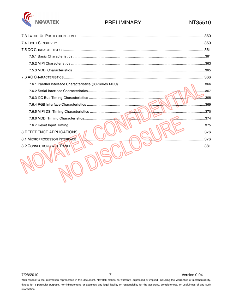
7.3 LATCH-UP PROTECTION LEVEL .........................................................................................................................360
7.4 LIGHT SENSITIVITY............................................................................................................................................360
7.5 DC CHARACTERISTICS......................................................................................................................................361
7.5.1 Basic Characteristics..........................................................................................................................................361
7.5.2 MIPI Characteristics............................................................................................................................................363
7.5.3 MDDI Characteristics ..........................................................................................................................................365
7.6 AC CHARACTERISTICS......................................................................................................................................366
7.6.1 Parallel Interface Characteristics (80-Series MCU) ..........................................................................................366
7.6.2 Serial Interface Characteristics..........................................................................................................................367
7.6.3 I2C Bus Timing Characteristics .........................................................................................................................368
7.6.4 RGB Interface Characteristics ...........................................................................................................................369
7.6.5 MIPI DSI Timing Characteristics ........................................................................................................................370
7.6.6 MDDI Timing Characteristics..............................................................................................................................374
7.6.7 Reset Input Timing..............................................................................................................................................375
8 REFERENCE APPLICATIONS.........................................................................................................................376
8.1 MICROPROCESSOR INTERFACE..........................................................................................................................376
8.2 CONNECTIONS WITH PANEL...............................................................................................................................381
7/28/2010
With respect to the information represented in this document, Novatek makes no warranty, expressed or implied, including the warranties of merchantability,
fitness for a particular purpose, non-infringement, or assumes any legal liability or responsibility for the accuracy, completeness, or usefulness of any such
information.
Version 0.04
7
�
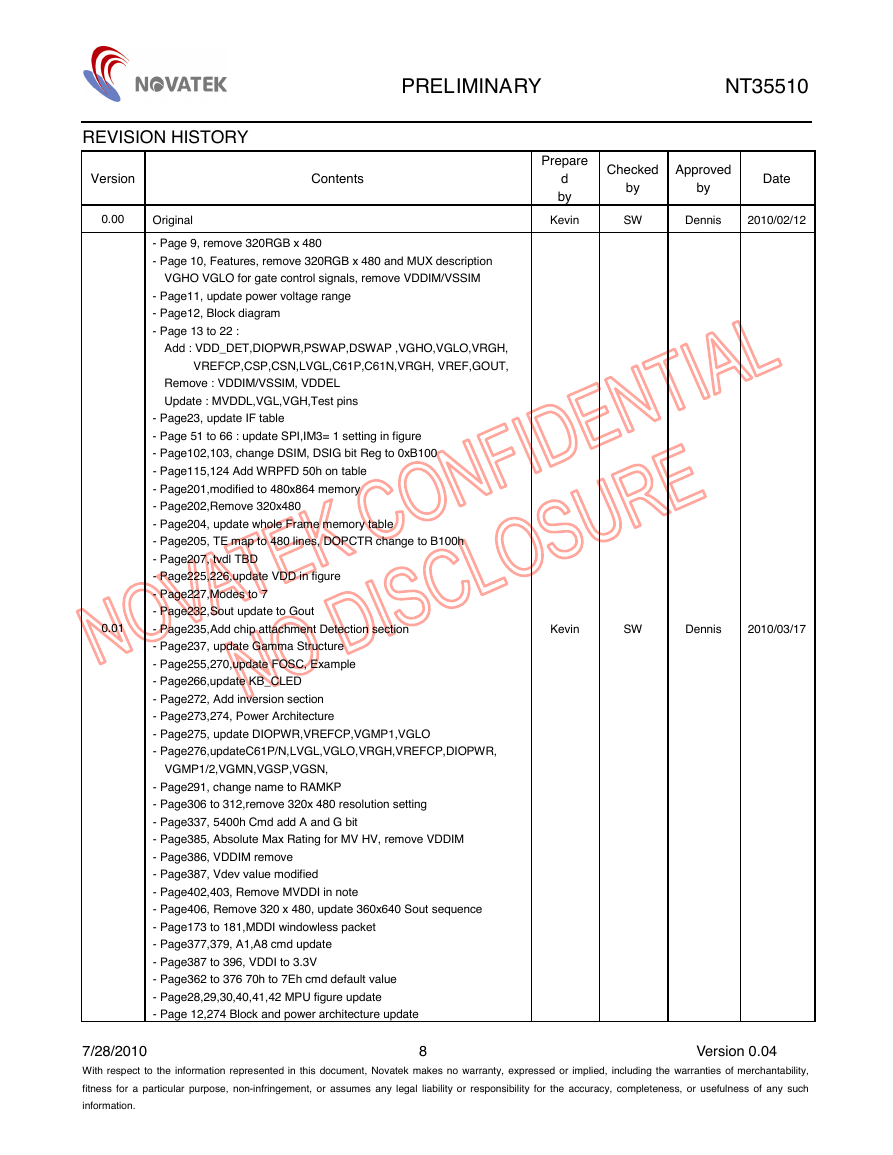
REVISION HISTORY
PRELIMINARY NT35510
Checked
Approved
by
Date
Prepare
d
by
Kevin
by
SW
Dennis
2010/02/12
Kevin
SW
Dennis
2010/03/17
Version
0.00
0.01
Contents
Original
- Page 9, remove 320RGB x 480
- Page 10, Features, remove 320RGB x 480 and MUX description
VGHO VGLO for gate control signals, remove VDDIM/VSSIM
- Page11, update power voltage range
- Page12, Block diagram
- Page 13 to 22 :
Add : VDD_DET,DIOPWR,PSWAP,DSWAP ,VGHO,VGLO,VRGH,
VREFCP,CSP,CSN,LVGL,C61P,C61N,VRGH, VREF,GOUT,
Remove : VDDIM/VSSIM, VDDEL
Update : MVDDL,VGL,VGH,Test pins
- Page23, update IF table
- Page 51 to 66 : update SPI,IM3= 1 setting in figure
- Page102,103, change DSIM, DSIG bit Reg to 0xB100
- Page115,124 Add WRPFD 50h on table
- Page201,modified to 480x864 memory
- Page202,Remove 320x480
- Page204, update whole Frame memory table
- Page205, TE map to 480 lines, DOPCTR change to B100h
- Page207, tvdl TBD
- Page225,226,update VDD in figure
- Page227,Modes to 7
- Page232,Sout update to Gout
- Page235,Add chip attachment Detection section
- Page237, update Gamma Structure
- Page255,270,update FOSC, Example
- Page266,update KB_CLED
- Page272, Add inversion section
- Page273,274, Power Architecture
- Page275, update DIOPWR,VREFCP,VGMP1,VGLO
- Page276,updateC61P/N,LVGL,VGLO,VRGH,VREFCP,DIOPWR,
VGMP1/2,VGMN,VGSP,VGSN,
- Page291, change name to RAMKP
- Page306 to 312,remove 320x 480 resolution setting
- Page337, 5400h Cmd add A and G bit
- Page385, Absolute Max Rating for MV HV, remove VDDIM
- Page386, VDDIM remove
- Page387, Vdev value modified
- Page402,403, Remove MVDDI in note
- Page406, Remove 320 x 480, update 360x640 Sout sequence
- Page173 to 181,MDDI windowless packet
- Page377,379, A1,A8 cmd update
- Page387 to 396, VDDI to 3.3V
- Page362 to 376 70h to 7Eh cmd default value
- Page28,29,30,40,41,42 MPU figure update
- Page 12,274 Block and power architecture update
7/28/2010
With respect to the information represented in this document, Novatek makes no warranty, expressed or implied, including the warranties of merchantability,
fitness for a particular purpose, non-infringement, or assumes any legal liability or responsibility for the accuracy, completeness, or usefulness of any such
information.
Version 0.04
8
�


 2023年江西萍乡中考道德与法治真题及答案.doc
 2012年重庆南川中考生物真题及答案.doc
 2013年江西师范大学地理学综合及文艺理论基础考研真题.doc
 2020年四川甘孜小升初语文真题及答案I卷.doc
 2020年注册岩土工程师专业基础考试真题及答案.doc
 2023-2024学年福建省厦门市九年级上学期数学月考试题及答案.doc
 2021-2022学年辽宁省沈阳市大东区九年级上学期语文期末试题及答案.doc
 2022-2023学年北京东城区初三第一学期物理期末试卷及答案.doc
 2018上半年江西教师资格初中地理学科知识与教学能力真题及答案.doc
 2012年河北国家公务员申论考试真题及答案-省级.doc
 2020-2021学年江苏省扬州市江都区邵樊片九年级上学期数学第一次质量检测试题及答案.doc
 2022下半年黑龙江教师资格证中学综合素质真题及答案.doc