IBIS
(I/O Buffer Information Specification)
Version 7.0
Ratified xxx
Draft 2
© IBIS Open Forum 2018
�
Contents
1
2
3
4
5
6
3.1
3.2
3.3
6.1
6.2
6.3
6.3.1
6.3.2
6.3.3
6.3.4
6.3.5
6.3.6
6.4.1
6.4.2
6.4
General Introduction ....................................................................................................... 8
Statement of Intent ........................................................................................................... 9
General Syntax Rules and Guidelines .......................................................................... 15
File Naming Definitions .............................................................................................. 15
Syntax Rules ................................................................................................................ 16
Keyword Hierarchy ...................................................................................................... 18
File Header and File End Information ......................................................................... 25
Component Description ................................................................................................. 28
Buffer Modeling .............................................................................................................. 47
Model Statement .......................................................................................................... 47
Add Submodel Description .......................................................................................... 95
Multi-Lingual Model Extensions ............................................................................... 109
Introduction .......................................................................................................... 109
Languages Supported ........................................................................................... 110
Overview .............................................................................................................. 110
Definitions ........................................................................................................... 111
General Assumptions ........................................................................................... 111
Keyword Definitions ............................................................................................ 116
Test Load and Data Description ................................................................................ 153
Introduction .......................................................................................................... 153
Keyword Definitions ............................................................................................ 153
Package Modeling ........................................................................................................ 157
Introduction ................................................................................................................ 157
Rules of Precedence ................................................................................................... 157
Keyword Definitions .................................................................................................. 157
Electrical Board Description ....................................................................................... 173
Introduction ................................................................................................................ 173
Keyword Definitions .................................................................................................. 174
Notes on Data Derivation Method .............................................................................. 183
Algorithmic Modeling .................................................................................................. 189
Algorithmic Modeling Interface (AMI) ..................................................................... 189
Introduction .......................................................................................................... 189
Keyword DefinItions ........................................................................................... 191
AMI Executable Model File Programming Guide .................................................... 194
Overview .............................................................................................................. 194
Application Scenarios .......................................................................................... 195
Function Signatures ............................................................................................. 200
Code Segment Examples ..................................................................................... 211
AMI Parameter Definition File Structure .................................................................. 212
Introduction .......................................................................................................... 212
AMI Parameter Definition File Organization ...................................................... 212
Parameter Rules Summary ................................................................................... 213
Reserved Word Rules .......................................................................................... 214
Combination and Corner Rules ............................................................................ 221
Processing and Passing Parameter String Rules .................................................. 222
7
8
7.1
7.2
7.3
8.1
8.2
9
10
10.1
10.2
10.1.1
10.1.2
10.2.1
10.2.2
10.2.3
10.2.4
10.3.1
10.3.2
10.3.3
10.3.4
10.3.5
10.3.6
10.3
2
�
10.4
10.5
10.6
10.3.7
10.4.1
10.5.1
10.6.1
10.6.2
10.6.3
10.7
10.8
10.9
10.7.1
10.8.1
10.9.1
10.9.2
10.9.3
10.10
10.10.1
10.10.2
10.10.3
10.10.4
10.11
10.11.1
Summary Table for Type and Format .................................................................. 223
General Reserved Parameters .................................................................................... 224
Summary Tables for Usage, Type and Format .................................................... 229
Reserved Parameters for Data Management .............................................................. 232
Summary Tables for Usage, Type and Format .................................................... 234
Jitter and Noise Reserved Parameters ........................................................................ 235
Tx-only Reserved Parameters .............................................................................. 235
Rx-only Reserved Parameters .............................................................................. 240
Summary Tables for Usage, Type and Format .................................................... 249
Modulation Reserved Parameters .............................................................................. 253
Summary Tables for Usage, Type and Format .................................................... 258
Repeaters .................................................................................................................... 260
Summary Tables for Usage, Type and Format .................................................... 262
AMI Reserved Parameter Definitions For Link Training Communications ............. 266
Training/Analysis Flow for Channels with No Repeater ..................................... 270
Training/Analysis Flow for Channels with One Repeater ................................... 271
Summary Tables for Usage, Type and Format .................................................... 272
Alternative AMI Analog Buffer Modeling ................................................................ 274
Transmitter Analog Circuit .................................................................................. 274
Receiver Analog Circuit ...................................................................................... 274
Reserved Parameter Definitions .......................................................................... 276
Summary Tables for Usage, Type and Format .................................................... 277
Model Specific Parameters ........................................................................................ 279
Tapped Delay Line Example ............................................................................... 279
Reserved Parameter and Data Type Rule Summary Tables ...................................... 281
Interconnect Modeling ................................................................................................. 292
Introduction ................................................................................................................ 292
General Interconnect Syntax Requirements .............................................................. 296
Connecting Pins, Pads and Buffer Terminals ...................................................... 308
EMI Parameters ........................................................................................................... 327
10.12
11
11.1
11.2
11.2.1
12
3
�
Figures
Figure 1 – Example of File Naming Definitions .............................................................................. 15
Figure 2 – Reference Load Connections ........................................................................................... 49
Figure 3 – Single-Ended or True Differential Buffer ....................................................................... 50
Figure 4 – Receiver Voltage with Hysteresis Thresholds ................................................................. 53
Figure 5 – Receiver Voltage with Static and Dynamic Overshoot Limits ....................................... 54
Figure 6 – Receiver Voltage with Dynamic Area Overshoot Limits ............................................... 55
Figure 7 – Receiver Voltage with Pulse Immunity Thresholds ........................................................ 56
Figure 8 – Low State (Logic Zero) Isso_pd Data Collection ........................................................... 73
Figure 9 – High State (Logic One) Isso_pu Data Collection ............................................................ 74
Figure 10 – Reference Data Collection ............................................................................................. 75
Figure 11 – Reference Data Collection with Supply Modulation .................................................... 75
Figure 12 – [Rgnd], [Rpower], [Rac], [Cac] in Relation to Package and Buffer Data ..................... 78
Figure 13 – Series Element Associations ......................................................................................... 80
Figure 14 – [Series Current] Voltage Priority and Current Direction .............................................. 81
Figure 15 – [Series MOSFET] Voltage Polarities and Current Direction ........................................ 82
Figure 16 – [Rising Waveform] and [Falling Waveform] Fixtures .................................................. 86
Figure 17 – [External Reference] - Used Only for Non-driver Modes ............................................. 89
Figure 18 – [Composite Current] Internal Current Paths ................................................................. 90
Figure 19 – [GND Pulse Table] Waveforms at Die .......................................................................... 99
Figure 20 – Port Names for I/O Buffer ........................................................................................... 113
Figure 21 – Port Names for Series Switch ...................................................................................... 113
Figure 22 – Example Showing [External Circuit] Ports ................................................................. 114
Figure 23 – AMS Model Unit, Using an I/O Buffer as an Example .............................................. 115
Figure 24 – An Analog-Only Model Unit, Using an I/O Buffer as an Example ............................ 116
Figure 25 – Multi-lingual [External Model] I/O Buffer ................................................................. 123
Figure 26 – Multi-lingual Pseudo-differential I/O Buffer .............................................................. 125
Figure 27 – Multi-lingual *-AMS I/O Buffers ............................................................................... 126
Figure 28 – Port Names for True Differential I/O Buffer ............................................................... 127
Figure 29 – Multi-lingual True Differential Buffer ........................................................................ 128
Figure 30 – Reference Example for [Node Declarations] Keyword............................................... 150
Figure 31 – [Test Load] Elements and Placement .......................................................................... 155
Figure 32 – Package Matrix Voltage Polarities and Current Directions ........................................ 166
Figure 33 – SIMM Package Path Example ..................................................................................... 178
Figure 34 – Fork and Endfork in [Path Description] ...................................................................... 179
Figure 35 – Discrete Series Element in [Path Description] ............................................................ 179
Figure 36 – Series Passive Components as Differential Termination ............................................ 180
Figure 37 – Paths Connected by Series Resistors as Differential Terminators .............................. 181
Figure 38 – Example of TTgnd Extraction Setup ........................................................................... 187
Figure 39 – Example of Series MOSFET Table Extraction ........................................................... 188
Figure 40 – Repeater Model ........................................................................................................... 260
Figure 41 – Repeater Link .............................................................................................................. 263
Figure 42 – Transmitter Analog Circuit ......................................................................................... 274
Figure 43 – Receiver Analog Circuit .............................................................................................. 275
Figure 44 – Example Interconnect Model Structure ....................................................................... 292
Figure 45 – Package Substrate I/O Paths ........................................................................................ 294
4
�
Figure 46 – Package Substrate Rail Terminals ............................................................................... 295
Figure 47 – Aggressor_Only Examples .......................................................................................... 307
Figure 48 – A Special Case with Aggressor_Only ......................................................................... 308
Figure 49 – Electrical Connections for Full Buffer Pin Model with Power Routing ..................... 314
Figure 50 – Electrical Terminals for Full Buffer Pin Model with Power Routing ......................... 315
5
�
Tables
Table 1 – Special Rules for Keyword [Model] ................................................................................. 47
Table 2 – Scheduled Model Initial State ........................................................................................... 64
Table 3 – Example of Setting Isso_pu and Isso_pd Values .............................................................. 76
Table 4 – Bus Hold without Off_Delay – Initialization ................................................................. 102
Table 5 – Bus Hold without Off_Delay – Transitions .................................................................... 103
Table 6 – Bus Hold with Off_Delay – Initialization ...................................................................... 103
Table 7 – Bus Hold with Off_Delay – Transitions ......................................................................... 103
Table 8 – Fall Back, Initial State .................................................................................................... 106
Table 9 – Fall Back, Driver Rising Cycle ....................................................................................... 106
Table 10 – Fall Back, Driver Falling Cycle .................................................................................... 106
Table 11 – Language Extension Keywords .................................................................................... 109
Table 12 – Port Names in Multi-Lingual Modeling ....................................................................... 112
Table 13 – Required Port Names for Single-ended Model_type Assignments .............................. 130
Table 14 – Required Port Names for Differential Model_type Assignments ................................. 130
Table 15 – Package Modeling Keywords ....................................................................................... 158
Table 16 – Voltage Ranges ............................................................................................................. 184
Table 17 – Allowable Data Types for Format Values .................................................................... 223
Table 18 – General Rules and Allowable Usage for General Reserved Parameters ...................... 230
Table 19 – Allowable Data Types for General Reserved Parameters ............................................ 230
Table 20 – Allowable Data Formats for General Reserved Parameters ......................................... 231
Table 21 – General Rules and Allowable Usage for Supporting Files Reserved Parameters ........ 234
Table 22 – Allowable Data Types for Supporting Files Reserved Parameters .............................. 234
Table 23 – Allowable Data Formats for Supporting Files Reserved Parameters ........................... 235
Table 24 – General Rules and Allowable Usage for Jitter and Noise Reserved Parameters .......... 250
Table 25 – Allowable Data Types for Jitter and Noise Reserved Parameters ................................ 250
Table 26 – Allowable Data Formats for Jitter and Noise Reserved Parameters ............................. 251
Table 27 – General Rules and Allowable Usage for Modulation Reserved Parameters ................ 258
Table 28 – Allowable Data Types for Modulation Reserved Parameters ...................................... 258
Table 29 – Allowable Data Formats for Modulation Reserved Parameters ................................... 259
Table 30 – General Rules and Allowable Usage for Repeater Reserved Parameters ..................... 262
Table 31 – Allowable Data Types for Repeater Reserved Parameters ........................................... 262
Table 32 – Allowable Data Formats for Repeater Reserved Parameters ....................................... 262
Table 33 – General Rules and Allowable Usage for BCI Reserved Parameters ............................ 273
Table 34 – Allowable Data Types for BCI Reserved Parameters .................................................. 273
Table 35 – Allowable Data Formats for BCI Reserved Parameters ............................................... 273
Table 36 – General Rules and Allowable Usage for Alternative Analog Modeling Reserved
Parameters ................................................................................................................. 277
Table 37 – Allowable Data Types for Alternative Analog Modeling Reserved Parameters .......... 278
Table 38 – Allowable Data Formats for Alternative Analog Modeling Reserved Parameters ...... 278
Table 39 – Reserved Parameters and Supported AMI_Versions ................................................... 281
Table 40 – General Rules and Allowable Usage for Reserved Parameters .................................... 282
Table 41 – Allowable Data Types for Reserved Parameters .......................................................... 284
Table 42 – Allowable Data Formats for Reserved Parameters ....................................................... 286
Table 43 – Allowable Data Types for Format Values .................................................................... 287
Table 44 – Defined Directions for Reserved Parameters ............................................................... 288
6
�
Table 45 – [Algorithmic Model] Subparameter and [Model] Model_Type Interaction ................. 290
Table 46 – Interconnect Modeling Keywords and Subparameters ................................................. 296
Table 47 – Allowed Terminal_type Associations1 ......................................................................... 310
7
�
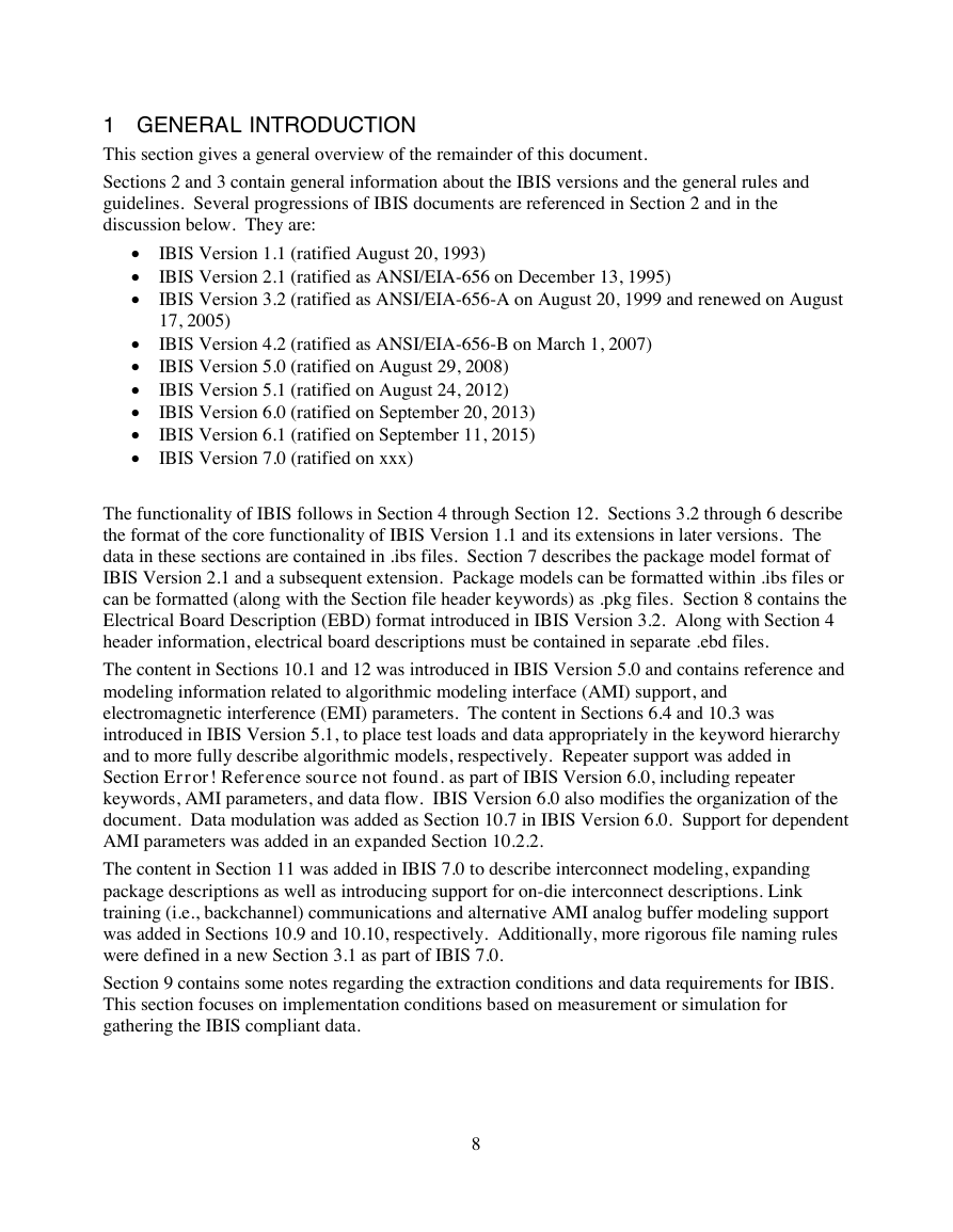
1 GENERAL INTRODUCTION
This section gives a general overview of the remainder of this document.
Sections 2 and 3 contain general information about the IBIS versions and the general rules and
guidelines. Several progressions of IBIS documents are referenced in Section 2 and in the
discussion below. They are:
•
•
•
•
•
•
•
•
•
IBIS Version 1.1 (ratified August 20, 1993)
IBIS Version 2.1 (ratified as ANSI/EIA-656 on December 13, 1995)
IBIS Version 3.2 (ratified as ANSI/EIA-656-A on August 20, 1999 and renewed on August
17, 2005)
IBIS Version 4.2 (ratified as ANSI/EIA-656-B on March 1, 2007)
IBIS Version 5.0 (ratified on August 29, 2008)
IBIS Version 5.1 (ratified on August 24, 2012)
IBIS Version 6.0 (ratified on September 20, 2013)
IBIS Version 6.1 (ratified on September 11, 2015)
IBIS Version 7.0 (ratified on xxx)
The functionality of IBIS follows in Section 4 through Section 12. Sections 3.2 through 6 describe
the format of the core functionality of IBIS Version 1.1 and its extensions in later versions. The
data in these sections are contained in .ibs files. Section 7 describes the package model format of
IBIS Version 2.1 and a subsequent extension. Package models can be formatted within .ibs files or
can be formatted (along with the Section file header keywords) as .pkg files. Section 8 contains the
Electrical Board Description (EBD) format introduced in IBIS Version 3.2. Along with Section 4
header information, electrical board descriptions must be contained in separate .ebd files.
The content in Sections 10.1 and 12 was introduced in IBIS Version 5.0 and contains reference and
modeling information related to algorithmic modeling interface (AMI) support, and
electromagnetic interference (EMI) parameters. The content in Sections 6.4 and 10.3 was
introduced in IBIS Version 5.1, to place test loads and data appropriately in the keyword hierarchy
and to more fully describe algorithmic models, respectively. Repeater support was added in
Section Error! Reference source not found. as part of IBIS Version 6.0, including repeater
keywords, AMI parameters, and data flow. IBIS Version 6.0 also modifies the organization of the
document. Data modulation was added as Section 10.7 in IBIS Version 6.0. Support for dependent
AMI parameters was added in an expanded Section 10.2.2.
The content in Section 11 was added in IBIS 7.0 to describe interconnect modeling, expanding
package descriptions as well as introducing support for on-die interconnect descriptions. Link
training (i.e., backchannel) communications and alternative AMI analog buffer modeling support
was added in Sections 10.9 and 10.10, respectively. Additionally, more rigorous file naming rules
were defined in a new Section 3.1 as part of IBIS 7.0.
Section 9 contains some notes regarding the extraction conditions and data requirements for IBIS.
This section focuses on implementation conditions based on measurement or simulation for
gathering the IBIS compliant data.
8
�






 2023年江西萍乡中考道德与法治真题及答案.doc
 2012年重庆南川中考生物真题及答案.doc
 2013年江西师范大学地理学综合及文艺理论基础考研真题.doc
 2020年四川甘孜小升初语文真题及答案I卷.doc
 2020年注册岩土工程师专业基础考试真题及答案.doc
 2023-2024学年福建省厦门市九年级上学期数学月考试题及答案.doc
 2021-2022学年辽宁省沈阳市大东区九年级上学期语文期末试题及答案.doc
 2022-2023学年北京东城区初三第一学期物理期末试卷及答案.doc
 2018上半年江西教师资格初中地理学科知识与教学能力真题及答案.doc
 2012年河北国家公务员申论考试真题及答案-省级.doc
 2020-2021学年江苏省扬州市江都区邵樊片九年级上学期数学第一次质量检测试题及答案.doc
 2022下半年黑龙江教师资格证中学综合素质真题及答案.doc