REMOTE CONTROL PANEL
RCP-1500
RCP-1501
RCP-1530
OPERATION MANUAL [English]
1st Edition (Revised 6)
�
Menus...................................................................... 50
Menu Operations ...........................................................50
Menu Tree .....................................................................52
Status Screen ................................................................54
Paint Menu ....................................................................54
File Menu ......................................................................64
Maintenance Menu ........................................................65
Config Menu ..................................................................72
To set the return input settings ................................78
To control the CCU menu ........................................78
To control the CAMERA/BPU menu ........................78
To change RCP assignments ..................................79
Multi Menu .....................................................................80
Function Menu ..............................................................80
Scene Menu ..................................................................81
About “Memory Stick Duo”................................... 82
Inserting a “Memory Stick Duo” .....................................82
Protecting Saved Data ..................................................82
Precautions ...................................................................82
Specifications......................................................... 83
Table of Contents
Precautions................................................................ 3
Overview .................................................................... 4
Features .......................................................................... 4
Examples of System Configurations ............................... 5
Supported devices .......................................................... 7
Operating Cameras ........................................................ 7
Names and Functions of Parts ................................ 8
Operation Panel .............................................................. 8
Connector Panel ........................................................... 26
Installation ............................................................... 27
Connection Precautions ................................................ 27
Setting the Status Screen Display ................................ 27
Setting the Clock ........................................................... 29
Setting the LAN Connection ......................................... 30
Setting LEGACY Mode ................................................. 30
Setting BRIDGE Mode .................................................. 31
Setting Multi-Camera System (MCS) Mode .................. 32
Changing the Output Destination for Previews ............. 33
Settings .................................................................... 34
Setting the User Interface ............................................. 34
To set the sounds .................................................... 34
To set the brightness of the LEDs ........................... 35
To adjust the LCD ................................................... 35
To illuminate character display in dark places ........ 36
To change the sensitivity of the adjustment
knobs ................................................................... 37
To set the screen saver ........................................... 37
To perform RPN correction ..................................... 38
Setting Security Restrictions ......................................... 39
To set the security level .......................................... 39
To protect operations with a security code .............. 40
Operation Settings ........................................................ 42
To set PIX/WF operation ......................................... 42
Customization ............................................................... 43
To assign functions to assignable buttons .............. 43
To assign functions to assignable adjustment
knobs ................................................................... 44
To set the custom paint menu ................................. 45
To assign menus to custom buttons ....................... 46
Saving and Initializing Settings ..................................... 48
To save changed setting values to a “Memory Stick
Duo” ..................................................................... 48
2 Table of Contents
�
Precautions
Note on faulty pixels on the LCD panel
The LCD panel fitted to this unit is manufactured with high
precision technology, giving a functioning pixel ratio of at least
99.99%. Thus a very small proportion of pixels may be “stuck,”
either always off (black), always on (red, green, or blue), or
flashing. In addition, over a long period of use, because of the
physical characteristics of the liquid crystal display, such
“stuck” pixels may appear spontaneously. These problems are
not a malfunction.
Cleaning the touch panel
When cleaning the touch panel display, use a soft cloth and
some ethanol to gently wipe only the area that is dirty. Using
too much ethanol or broad wiping may result in smearing.
You can also use a soft, dry cloth such as that used for
cleaning glasses to gently wipe off the dirt.
Notes
Do not clean the touch panel with water or any chemical
substances other than ethanol.
When wiping the touch panel, take proper care to prevent
any liquid from entering between the touch panel and the
body of the unit.
Using excessive force when wiping may result in scratches
on the touch panel.
Note on interference
Do not place mobile phones or similar devices on the control
panel. Doing so may result in malfunction of the unit.
Precautions
3
�
Overview
Features
The MSU-1000 series and RCP-1000 series are remote
control panels for configuring and controlling Sony’s studio
and broadcast cameras.
This section describes the features that are common between
the MSU-1000 series and RCP-1000 series.
Remote control panels
The RCP-1000 series of remote control panels is designed
mainly for operation. Use a remote control panel with a camera
on a one-to-one basis.
The RCP-1530 incorporates an LCD display with a touch
panel, and a variety of settings are available to make this
remote control panel compare favorably with the MSU. It is
multifunctional while at the same time having a slim body
that is just 80 mm wide, which allows you to mount up to five
units in a 19-inch EIA rack. The iris and master black
adjustment block employs joystick type control.
The RCP-1500 incorporates an LCD display with direct
operation switches and a touch panel, which makes it a
remote control panel that offers both ease of operation and
multifunctionality that compares favorably with the MSU.
The iris and master black adjustment block employs joystick
type control. Up to four units can be mounted in a 19-inch
EIA rack.
The RCP-1501 incorporates an LCD display with direct
operation switches and a touch panel, which makes it a
remote control panel that offers both ease of operation and
multifunctionality that compares favorably with the MSU.
The iris and master black adjustment block employs dial
(knob) type control. Up to four units can be mounted in a 19-
inch EIA rack.
Operability suitable for basic camera
operations
This remote control panel is provided with the control functions
required to perform the basic operations of cameras to enable
the simple and accurate operation of various functions. The
operation buttons, adjustment knobs, and other controls are
arranged on the panel according to function and frequency of
use. Guard frames are provided around buttons that are vital
to the operation and setup of cameras to prevent the buttons
from being unintentionally operated.
Illuminated buttons with high visibility flash and light to notify
you of the operation status to enable operation even in dark
locations. Likewise, an illuminated panel surface is employed
to allow you to confirm function names even when the
surroundings are dark.
Building of a variety of control systems
It is possible to connect by LAN cable in addition to connecting
using CCA-5 cable. Therefore, when setting up a multi-camera
control system, not only can a system be built using the
CNU-700 as previously, but a system can also be built using a
LAN. In a system that uses CNU-700s, two camera command
network units (CNUs) can be used to control a camera system
of up to 24 cameras. In a system that uses a LAN, a camera
system of up to 96 cameras can be controlled.
Support for operating multiple cameras
Various operations are made possible by using multiple
camera systems that support multiple cameras.
The following functions are provided to control the connected
cameras.
Panel active function
This function always enables one control panel for one
camera to prevent unintentional operation. Even with a
control panel that does not have the panel active
permission, a camera can be operated using the parallel
function, with the exception of iris and master black
operations.
RCP assignment function
This function changes the combination of an RCP and
camera system.1)
Master/subordinate function
This function makes changes in conjunction with the color
temperature of the specified camera system.1) 2)
Customizable functions
Various settings can be configured according to the operation
configuration and the frequency with which functions are used.
Menus
You can create a custom paint menu, and change the contents
and order of a menu.
Function restriction
You can restrict access to items of a certain level or above to
restrict the operators that can configure settings.
Switches
You can assign any function to a spare switch.
Adjustment knobs3)
You can assign any function to a spare adjustment knob.
Operation and call sounds
You can mute and adjust the volume of the operation and call
sounds if necessary.
Exporting and importing of settings
You can save the settings to a “Memory Stick Duo”, and then
export them to another remote control panel.
1) If multiple CNUs exist in the system, this only works for cameras
connected to the same CNU.
2) This does not work when connected to a network.
3) Customization of the adjustment knobs is only possible with the
RCP-1500/1501.
4 Overview
�
Examples of System Configurations
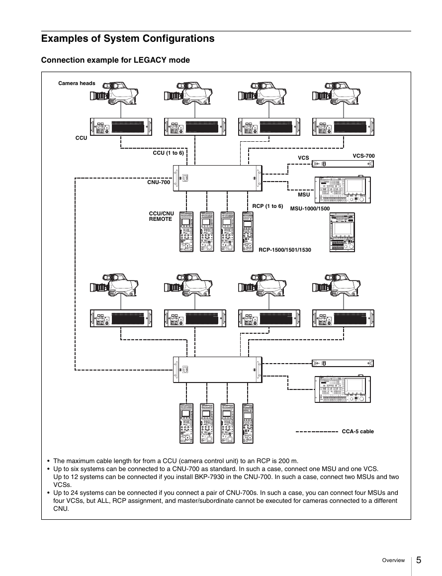
Connection example for LEGACY mode
Camera heads
CCU
CCU (1 to 6)
CNU-700
CCU/CNU
REMOTE
VCS-700
VCS
MSU
RCP (1 to 6)
MSU-1000/1500
RCP-1500/1501/1530
CCA-5 cable
The maximum cable length for from a CCU (camera control unit) to an RCP is 200 m.
Up to six systems can be connected to a CNU-700 as standard. In such a case, connect one MSU and one VCS.
Up to 12 systems can be connected if you install BKP-7930 in the CNU-700. In such a case, connect two MSUs and two
VCSs.
Up to 24 systems can be connected if you connect a pair of CNU-700s. In such a case, you can connect four MSUs and
four VCSs, but ALL, RCP assignment, and master/subordinate cannot be executed for cameras connected to a different
CNU.
Overview
5
�
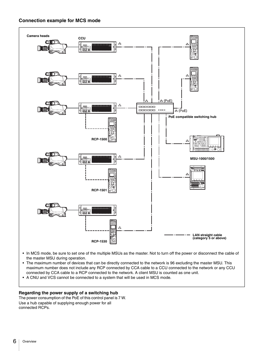
Connection example for MCS mode
Camera heads
CCU
PoE compatible switching hub
MSU-1000/1500
LAN straight cable
(category 5 or above)
RCP-1500
RCP-1501
RCP-1530
In MCS mode, be sure to set one of the multiple MSUs as the master. Not to turn off the power or disconnect the cable of
the master MSU during operation.
The maximum number of devices that can be directly connected to the network is 96 excluding the master MSU. This
maximum number does not include any RCP connected by CCA cable to a CCU connected to the network or any CCU
connected by CCA cable to a RCP connected to the network. A client MSU is counted as one unit.
A CNU and VCS cannot be connected to a system that will be used in MCS mode.
Regarding the power supply of a switching hub
The power consumption of the PoE of this control panel is 7 W.
Use a hub capable of supplying enough power for all
connected RCPs.
6 Overview
�
Supported devices
Operating Cameras
This unit supports connection to the following devices.
BVP-E30 series
CCU-590/790 series
HDC1000(R)/1500(R)/3300(R) series
HDCU1000/1500/3300(R) series
HDC2000/2500 series
HDCU2000/2500 series
HSC-300/HSCU-300 series
HXC-100/HXCU-100 series
HXC-D70/HXCU-D70 series
HDC-P1
HDFA-200
F23/F35
SRW-9000/SRW-9000PL
PDW-700/740/F800
HSC300RF/300R/100RF/100R
HSCU300RF/300R
CA4000
BPU8000/4000
For details about the devices other than the above, refer to the
connecting information for each device.
Notes
Proper functioning may not be possible depending on the
firmware version. Be sure to update to the latest version
before use.
The functions that are available on the control panel may be
limited depending on the connected camera. Some controls
may not function with certain cameras, but this is not a
malfunction.
Camera control permissions (panel active,
IRIS/MB active, and PARA)
By combining an MSU and RCP, you can operate one camera
device from multiple control panels, and multiple cameras from
one MSU. This is called a “multi-camera system.” A multi-
camera system can be implemented by introducing a CNU or
by establishing a LAN connection in MCS mode.
To prevent unintentional operation in a multi-camera system,
permission is granted to operate the cameras for only either
the connected MSU or RCP. There are three types of
permission.
Panel active
Even if multiple control panels are connected to one camera,
only one control panel has the control permission. This
panel is referred to as “active.”
An inactive control panel can only be used to display the
status.
PARA (parallel control)
By enabling the PARA function on an inactive control panel,
you can control cameras. The PARA function is enabled
from an inactive control panel, but can be disabled from any
control panel.
IRIS/MB active
To prevent unintentional operation of IRIS and master black,
you can choose the control panels on which to activate
IRIS/MB. The PARA function does not operate.
Operating an inactive control panel on which PARA is
disabled will not change the state of the camera.
White balance link (master/subordinate mode)
The color temperature of light shining on the subject varies
moment by moment when you shoot outdoors. When
correcting for this, you can link the cameras within the system
and then control them. When you do this, set the camera that
is to be controlled directly to “Master,” and the cameras that
are to be linked to “Subordinate.”
When you change the white balance of the control panel to
which the master camera is connected, the subordinate
cameras are corrected by the same correction amount.
However, adjusting a subordinate camera does not affect any
of the other cameras.
The white balance link function is only enabled when there is
a connection to a CNU (LEGACY mode).
Note
The functions that are available on the control panel may be
limited depending on the connected camera. Some controls
may not function with certain cameras, but this is not a
malfunction.
Overview
7
�
Names and Functions of Parts
Operation Panel
RCP-1500
RCP-1530
Camera/panel control block
(RCP-1500/1501) (page 9)
Camera/panel control block
(RCP-1530) (page 11)
Menu operation block
(page 13)
Function control block
(RCP-1500/1501) (page 14)
Menu operation block
(page 13)
Function control block
(RCP-1530) (page 16)
Adjustment block (RCP-1500)
(page 17)
Adjustment block (RCP-1530)
(page 21)
Panel control/status display
block (RCP-1500) (page 23)
Panel control/status display
block (RCP-1530) (page 25)
RCP-1501
Adjustment block (RCP-1501)
(page 19)
Panel control/status display
block (RCP-1501) (page 24)
8 Names and Functions of Parts
�


 2023年江西萍乡中考道德与法治真题及答案.doc
 2012年重庆南川中考生物真题及答案.doc
 2013年江西师范大学地理学综合及文艺理论基础考研真题.doc
 2020年四川甘孜小升初语文真题及答案I卷.doc
 2020年注册岩土工程师专业基础考试真题及答案.doc
 2023-2024学年福建省厦门市九年级上学期数学月考试题及答案.doc
 2021-2022学年辽宁省沈阳市大东区九年级上学期语文期末试题及答案.doc
 2022-2023学年北京东城区初三第一学期物理期末试卷及答案.doc
 2018上半年江西教师资格初中地理学科知识与教学能力真题及答案.doc
 2012年河北国家公务员申论考试真题及答案-省级.doc
 2020-2021学年江苏省扬州市江都区邵樊片九年级上学期数学第一次质量检测试题及答案.doc
 2022下半年黑龙江教师资格证中学综合素质真题及答案.doc