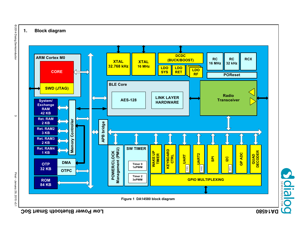
1. Block diagram
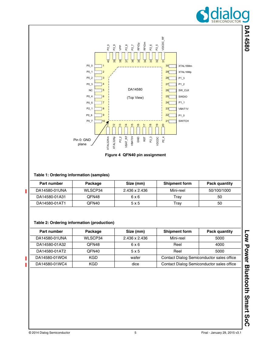
2. Pinout
Table 1: Ordering information (samples)
Table 2: Ordering information (production)
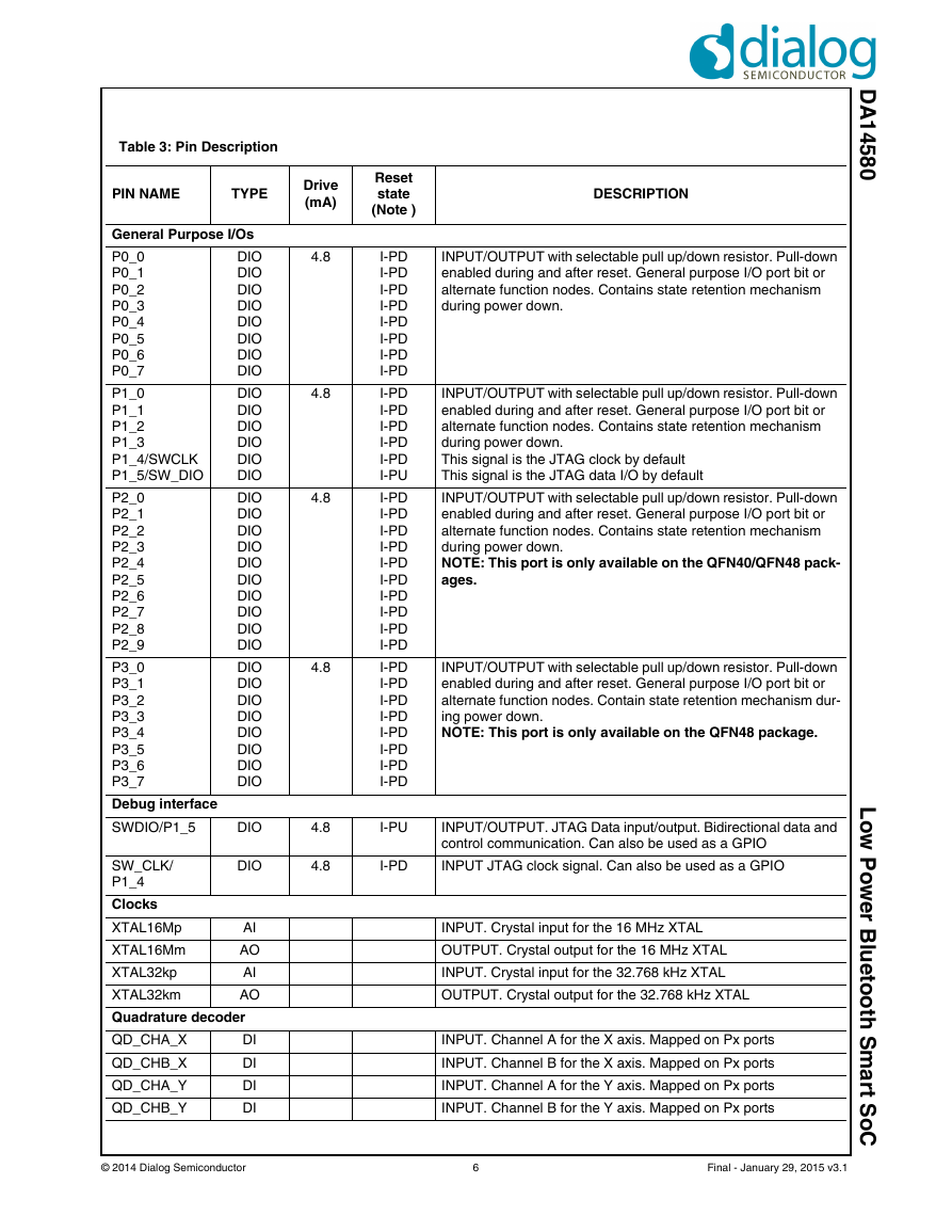
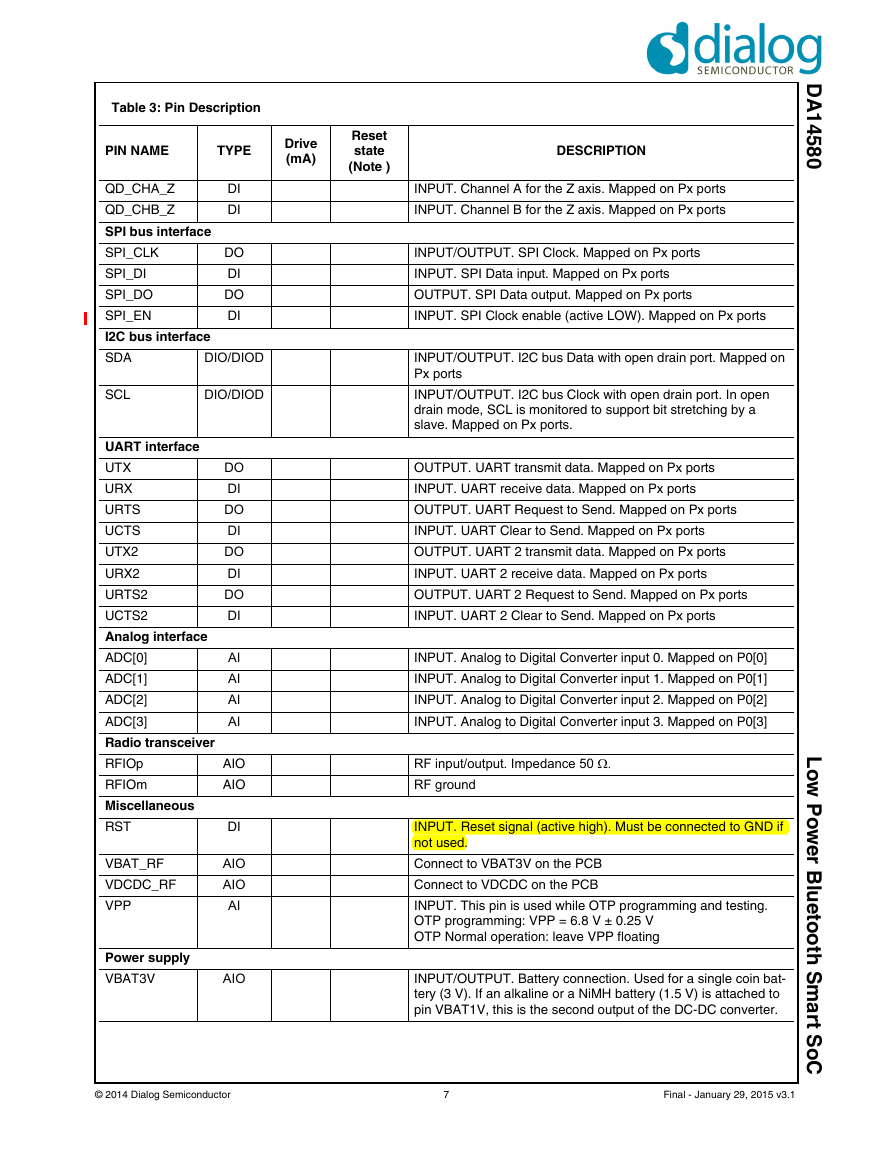
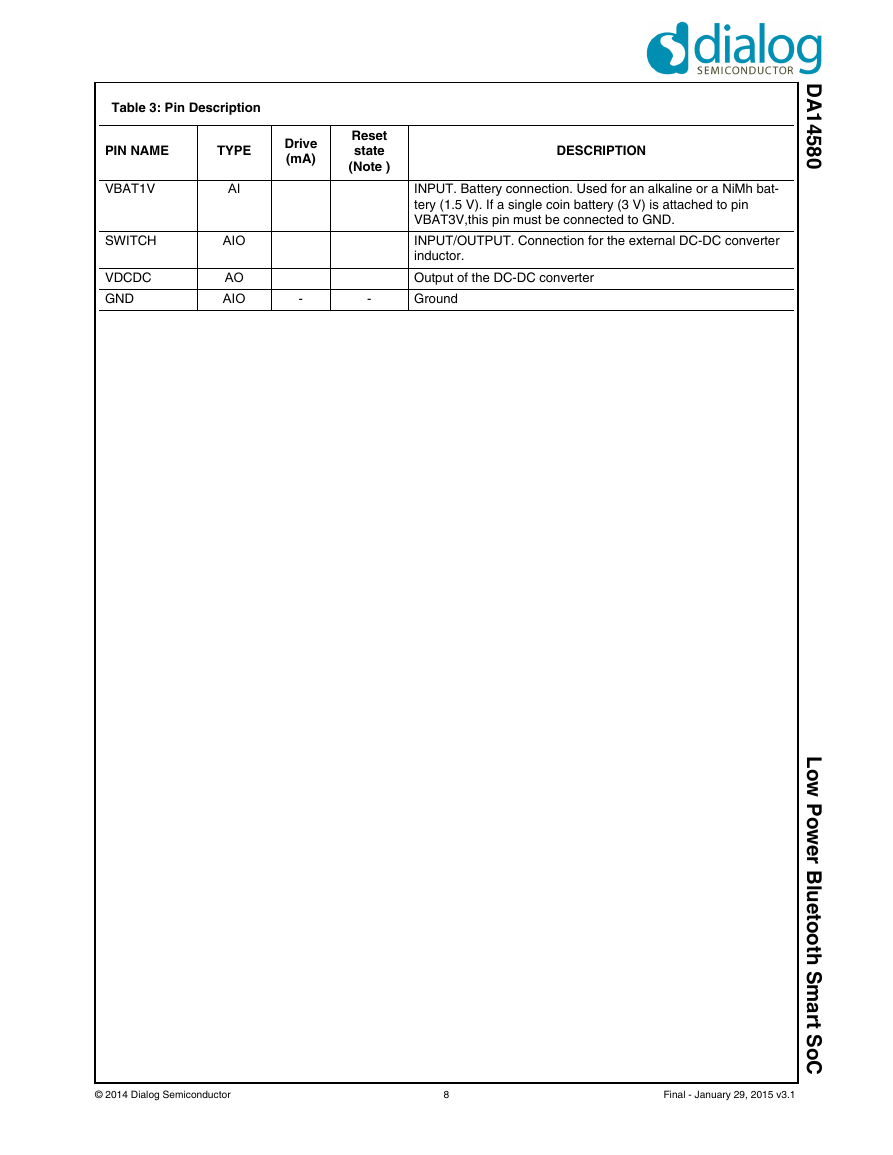
Table 3: Pin Description
3. System overview
3.1 ARM Cortex-M0 CPU
3.2 Bluetooth Smart
3.2.1 BLE Core
3.2.2 Radio Transceiver
3.2.3 SmartSnippetsä
3.3 Memories
3.4 Functional Modes
3.5 Power Modes
3.6 Interfaces
3.6.1 UARTs
3.6.2 SPI+
3.6.3 I2C interface
3.6.4 General purpose ADC
3.6.5 Quadrature decoder
3.6.6 Keyboard controller
3.6.7 Input/output ports
3.7 Timers
3.7.1 General purpose timers
3.7.2 Wake-Up timer
3.7.3 Watchdog timer
3.8 Clock/Reset
3.8.1 Clocks
3.8.2 Reset
3.9 Power Management
4. Registers
Table 4: Register map
Table 5: OTPC_MODE_REG (0x40008000)
Table 6: OTPC_PCTRL_REG (0x40008004)
Table 7: OTPC_STAT_REG (0x40008008)
Table 8: OTPC_AHBADR_REG (0x4000800C)
Table 9: OTPC_CELADR_REG (0x40008010)
Table 10: OTPC_NWORDS_REG (0x40008014)
Table 11: OTPC_FFPRT_REG (0x40008018)
Table 12: OTPC_FFRD_REG (0x4000801C)
Table 13: PATCH_VALID_REG (0x40008400)
Table 14: PATCH_VALID_SET_REG (0x40008404)
Table 15: PATCH_VALID_RESET_REG (0x40008408)
Table 16: PATCH_ADDR0_REG (0x40008410)
Table 17: PATCH_DATA0_REG (0x40008414)
Table 18: PATCH_ADDR1_REG (0x40008418)
Table 19: PATCH_DATA1_REG (0x4000841C)
Table 20: PATCH_ADDR2_REG (0x40008420)
Table 21: PATCH_DATA2_REG (0x40008424)
Table 22: PATCH_ADDR3_REG (0x40008428)
Table 23: PATCH_DATA3_REG (0x4000842C)
Table 24: PATCH_ADDR4_REG (0x40008430)
Table 25: PATCH_DATA4_REG (0x40008434)
Table 26: PATCH_ADDR5_REG (0x40008438)
Table 27: PATCH_DATA5_REG (0x4000843C)
Table 28: PATCH_ADDR6_REG (0x40008440)
Table 29: PATCH_DATA6_REG (0x40008444)
Table 30: PATCH_ADDR7_REG (0x40008448)
Table 31: PATCH_DATA7_REG (0x4000844C)
Table 32: CLK_AMBA_REG (0x50000000)
Table 33: CLK_FREQ_TRIM_REG (0x50000002)
Table 34: CLK_PER_REG (0x50000004)
Table 35: CLK_RADIO_REG (0x50000008)
Table 36: CLK_CTRL_REG (0x5000000A)
Table 37: PMU_CTRL_REG (0x50000010)
Table 38: SYS_CTRL_REG (0x50000012)
Table 39: SYS_STAT_REG (0x50000014)
Table 40: TRIM_CTRL_REG (0x50000016)
Table 41: CLK_32K_REG (0x50000020)
Table 42: CLK_16M_REG (0x50000022)
Table 43: CLK_RCX20K_REG (0x50000024)
Table 44: BANDGAP_REG (0x50000028)
Table 45: ANA_STATUS_REG (0x5000002A)
Table 46: WKUP_CTRL_REG (0x50000100)
Table 47: WKUP_COMPARE_REG (0x50000102)
Table 48: WKUP_RESET_IRQ_REG (0x50000104)
Table 49: WKUP_COUNTER_REG (0x50000106)
Table 50: WKUP_RESET_CNTR_REG (0x50000108)
Table 51: WKUP_SELECT_P0_REG (0x5000010A)
Table 52: WKUP_SELECT_P1_REG (0x5000010C)
Table 53: WKUP_SELECT_P2_REG (0x5000010E)
Table 54: WKUP_SELECT_P3_REG (0x50000110)
Table 55: WKUP_POL_P0_REG (0x50000112)
Table 56: WKUP_POL_P1_REG (0x50000114)
Table 57: WKUP_POL_P2_REG (0x50000116)
Table 58: WKUP_POL_P3_REG (0x50000118)
Table 59: QDEC_CTRL_REG (0x50000200)
Table 60: QDEC_XCNT_REG (0x50000202)
Table 61: QDEC_YCNT_REG (0x50000204)
Table 62: QDEC_CLOCKDIV_REG (0x50000206)
Table 63: QDEC_CTRL2_REG (0x50000208)
Table 64: QDEC_ZCNT_REG (0x5000020A)
Table 65: UART_RBR_THR_DLL_REG (0x50001000)
Table 66: UART_IER_DLH_REG (0x50001004)
Table 67: UART_IIR_FCR_REG (0x50001008)
Table 68: UART_LCR_REG (0x5000100C)
Table 69: UART_MCR_REG (0x50001010)
Table 70: UART_LSR_REG (0x50001014)
Table 71: UART_MSR_REG (0x50001018)
Table 72: UART_SCR_REG (0x5000101C)
Table 73: UART_LPDLL_REG (0x50001020)
Table 74: UART_LPDLH_REG (0x50001024)
Table 75: UART_SRBR_STHR0_REG (0x50001030)
Table 76: UART_SRBR_STHR1_REG (0x50001034)
Table 77: UART_SRBR_STHR2_REG (0x50001038)
Table 78: UART_SRBR_STHR3_REG (0x5000103C)
Table 79: UART_SRBR_STHR4_REG (0x50001040)
Table 80: UART_SRBR_STHR5_REG (0x50001044)
Table 81: UART_SRBR_STHR6_REG (0x50001048)
Table 82: UART_SRBR_STHR7_REG (0x5000104C)
Table 83: UART_SRBR_STHR8_REG (0x50001050)
Table 84: UART_SRBR_STHR9_REG (0x50001054)
Table 85: UART_SRBR_STHR10_REG (0x50001058)
Table 86: UART_SRBR_STHR11_REG (0x5000105C)
Table 87: UART_SRBR_STHR12_REG (0x50001060)
Table 88: UART_SRBR_STHR13_REG (0x50001064)
Table 89: UART_SRBR_STHR14_REG (0x50001068)
Table 90: UART_SRBR_STHR15_REG (0x5000106C)
Table 91: UART_USR_REG (0x5000107C)
Table 92: UART_TFL_REG (0x50001080)
Table 93: UART_RFL_REG (0x50001084)
Table 94: UART_SRR_REG (0x50001088)
Table 95: UART_SRTS_REG (0x5000108C)
Table 96: UART_SBCR_REG (0x50001090)
Table 97: UART_SDMAM_REG (0x50001094)
Table 98: UART_SFE_REG (0x50001098)
Table 99: UART_SRT_REG (0x5000109C)
Table 100: UART_STET_REG (0x500010A0)
Table 101: UART_HTX_REG (0x500010A4)
Table 102: UART_CPR_REG (0x500010F4)
Table 103: UART_UCV_REG (0x500010F8)
Table 104: UART_CTR_REG (0x500010FC)
Table 105: UART2_RBR_THR_DLL_REG (0x50001100)
Table 106: UART2_IER_DLH_REG (0x50001104)
Table 107: UART2_IIR_FCR_REG (0x50001108)
Table 108: UART2_LCR_REG (0x5000110C)
Table 109: UART2_MCR_REG (0x50001110)
Table 110: UART2_LSR_REG (0x50001114)
Table 111: UART2_MSR_REG (0x50001118)
Table 112: UART2_SCR_REG (0x5000111C)
Table 113: UART2_LPDLL_REG (0x50001120)
Table 114: UART2_LPDLH_REG (0x50001124)
Table 115: UART2_SRBR_STHR0_REG (0x50001130)
Table 116: UART2_SRBR_STHR1_REG (0x50001134)
Table 117: UART2_SRBR_STHR2_REG (0x50001138)
Table 118: UART2_SRBR_STHR3_REG (0x5000113C)
Table 119: UART2_SRBR_STHR4_REG (0x50001140)
Table 120: UART2_SRBR_STHR5_REG (0x50001144)
Table 121: UART2_SRBR_STHR6_REG (0x50001148)
Table 122: UART2_SRBR_STHR7_REG (0x5000114C)
Table 123: UART2_SRBR_STHR8_REG (0x50001150)
Table 124: UART2_SRBR_STHR9_REG (0x50001154)
Table 125: UART2_SRBR_STHR10_REG (0x50001158)
Table 126: UART2_SRBR_STHR11_REG (0x5000115C)
Table 127: UART2_SRBR_STHR12_REG (0x50001160)
Table 128: UART2_SRBR_STHR13_REG (0x50001164)
Table 129: UART2_SRBR_STHR14_REG (0x50001168)
Table 130: UART2_SRBR_STHR15_REG (0x5000116C)
Table 131: UART2_USR_REG (0x5000117C)
Table 132: UART2_TFL_REG (0x50001180)
Table 133: UART2_RFL_REG (0x50001184)
Table 134: UART2_SRR_REG (0x50001188)
Table 135: UART2_SRTS_REG (0x5000118C)
Table 136: UART2_SBCR_REG (0x50001190)
Table 137: UART2_SDMAM_REG (0x50001194)
Table 138: UART2_SFE_REG (0x50001198)
Table 139: UART2_SRT_REG (0x5000119C)
Table 140: UART2_STET_REG (0x500011A0)
Table 141: UART2_HTX_REG (0x500011A4)
Table 142: UART2_CPR_REG (0x500011F4)
Table 143: UART2_UCV_REG (0x500011F8)
Table 144: UART2_CTR_REG (0x500011FC)
Table 145: SPI_CTRL_REG (0x50001200)
Table 146: SPI_RX_TX_REG0 (0x50001202)
Table 147: SPI_RX_TX_REG1 (0x50001204)
Table 148: SPI_CLEAR_INT_REG (0x50001206)
Table 149: SPI_CTRL_REG1 (0x50001208)
Table 150: I2C_CON_REG (0x50001300)
Table 151: I2C_TAR_REG (0x50001304)
Table 152: I2C_SAR_REG (0x50001308)
Table 153: I2C_DATA_CMD_REG (0x50001310)
Table 154: I2C_SS_SCL_HCNT_REG (0x50001314)
Table 155: I2C_SS_SCL_LCNT_REG (0x50001318)
Table 156: I2C_FS_SCL_HCNT_REG (0x5000131C)
Table 157: I2C_FS_SCL_LCNT_REG (0x50001320)
Table 158: I2C_INTR_STAT_REG (0x5000132C)
Table 159: I2C_INTR_MASK_REG (0x50001330)
Table 160: I2C_RAW_INTR_STAT_REG (0x50001334)
Table 161: I2C_RX_TL_REG (0x50001338)
Table 162: I2C_TX_TL_REG (0x5000133C)
Table 163: I2C_CLR_INTR_REG (0x50001340)
Table 164: I2C_CLR_RX_UNDER_REG (0x50001344)
Table 165: I2C_CLR_RX_OVER_REG (0x50001348)
Table 166: I2C_CLR_TX_OVER_REG (0x5000134C)
Table 167: I2C_CLR_RD_REQ_REG (0x50001350)
Table 168: I2C_CLR_TX_ABRT_REG (0x50001354)
Table 169: I2C_CLR_RX_DONE_REG (0x50001358)
Table 170: I2C_CLR_ACTIVITY_REG (0x5000135C)
Table 171: I2C_CLR_STOP_DET_REG (0x50001360)
Table 172: I2C_CLR_START_DET_REG (0x50001364)
Table 173: I2C_CLR_GEN_CALL_REG (0x50001368)
Table 174: I2C_ENABLE_REG (0x5000136C)
Table 175: I2C_STATUS_REG (0x50001370)
Table 176: I2C_TXFLR_REG (0x50001374)
Table 177: I2C_RXFLR_REG (0x50001378)
Table 178: I2C_SDA_HOLD_REG (0x5000137C)
Table 179: I2C_TX_ABRT_SOURCE_REG (0x50001380)
Table 180: I2C_SDA_SETUP_REG (0x50001394)
Table 181: I2C_ACK_GENERAL_CALL_REG (0x50001398)
Table 182: I2C_ENABLE_STATUS_REG (0x5000139C)
Table 183: I2C_IC_FS_SPKLEN_REG (0x500013A0)
Table 184: GPIO_IRQ0_IN_SEL_REG (0x50001400)
Table 185: GPIO_IRQ1_IN_SEL_REG (0x50001402)
Table 186: GPIO_IRQ2_IN_SEL_REG (0x50001404)
Table 187: GPIO_IRQ3_IN_SEL_REG (0x50001406)
Table 188: GPIO_IRQ4_IN_SEL_REG (0x50001408)
Table 189: GPIO_DEBOUNCE_REG (0x5000140C)
Table 190: GPIO_RESET_IRQ_REG (0x5000140E)
Table 191: GPIO_INT_LEVEL_CTRL_REG (0x50001410)
Table 192: KBRD_IRQ_IN_SEL0_REG (0x50001412)
Table 193: KBRD_IRQ_IN_SEL1_REG (0x50001414)
Table 194: KBRD_IRQ_IN_SEL2_REG (0x50001416)
Table 195: GP_ADC_CTRL_REG (0x50001500)
Table 196: GP_ADC_CTRL2_REG (0x50001502)
Table 197: GP_ADC_OFFP_REG (0x50001504)
Table 198: GP_ADC_OFFN_REG (0x50001506)
Table 199: GP_ADC_CLEAR_INT_REG (0x50001508)
Table 200: GP_ADC_RESULT_REG (0x5000150A)
Table 201: GP_ADC_DELAY_REG (0x5000150C)
Table 202: GP_ADC_DELAY2_REG (0x5000150E)
Table 203: CLK_REF_SEL_REG (0x50001600)
Table 204: CLK_REF_CNT_REG (0x50001602)
Table 205: CLK_REF_VAL_L_REG (0x50001604)
Table 206: CLK_REF_VAL_H_REG (0x50001606)
Table 207: P0_DATA_REG (0x50003000)
Table 208: P0_SET_DATA_REG (0x50003002)
Table 209: P0_RESET_DATA_REG (0x50003004)
Table 210: P00_MODE_REG (0x50003006)
Table 211: P01_MODE_REG (0x50003008)
Table 212: P02_MODE_REG (0x5000300A)
Table 213: P03_MODE_REG (0x5000300C)
Table 214: P04_MODE_REG (0x5000300E)
Table 215: P05_MODE_REG (0x50003010)
Table 216: P06_MODE_REG (0x50003012)
Table 217: P07_MODE_REG (0x50003014)
Table 218: P1_DATA_REG (0x50003020)
Table 219: P1_SET_DATA_REG (0x50003022)
Table 220: P1_RESET_DATA_REG (0x50003024)
Table 221: P10_MODE_REG (0x50003026)
Table 222: P11_MODE_REG (0x50003028)
Table 223: P12_MODE_REG (0x5000302A)
Table 224: P13_MODE_REG (0x5000302C)
Table 225: P14_MODE_REG (0x5000302E)
Table 226: P15_MODE_REG (0x50003030)
Table 227: P2_DATA_REG (0x50003040)
Table 228: P2_SET_DATA_REG (0x50003042)
Table 229: P2_RESET_DATA_REG (0x50003044)
Table 230: P20_MODE_REG (0x50003046)
Table 231: P21_MODE_REG (0x50003048)
Table 232: P22_MODE_REG (0x5000304A)
Table 233: P23_MODE_REG (0x5000304C)
Table 234: P24_MODE_REG (0x5000304E)
Table 235: P25_MODE_REG (0x50003050)
Table 236: P26_MODE_REG (0x50003052)
Table 237: P27_MODE_REG (0x50003054)
Table 238: P28_MODE_REG (0x50003056)
Table 239: P29_MODE_REG (0x50003058)
Table 240: P01_PADPWR_CTRL_REG (0x50003070)
Table 241: P2_PADPWR_CTRL_REG (0x50003072)
Table 242: P3_PADPWR_CTRL_REG (0x50003074)
Table 243: P3_DATA_REG (0x50003080)
Table 244: P3_SET_DATA_REG (0x50003082)
Table 245: P3_RESET_DATA_REG (0x50003084)
Table 246: P30_MODE_REG (0x50003086)
Table 247: P31_MODE_REG (0x50003088)
Table 248: P32_MODE_REG (0x5000308A)
Table 249: P33_MODE_REG (0x5000308C)
Table 250: P34_MODE_REG (0x5000308E)
Table 251: P35_MODE_REG (0x50003090)
Table 252: P36_MODE_REG (0x50003092)
Table 253: P37_MODE_REG (0x50003094)
Table 254: WATCHDOG_REG (0x50003100)
Table 255: WATCHDOG_CTRL_REG (0x50003102)
Table 256: CHIP_ID1_REG (0x50003200)
Table 257: CHIP_ID2_REG (0x50003201)
Table 258: CHIP_ID3_REG (0x50003202)
Table 259: CHIP_SWC_REG (0x50003203)
Table 260: CHIP_REVISION_REG (0x50003204)
Table 261: CHIP_CONFIG1_REG (0x50003205)
Table 262: CHIP_CONFIG2_REG (0x50003206)
Table 263: CHIP_CONFIG3_REG (0x50003207)
Table 264: CHIP_TEST1_REG (0x5000320A)
Table 265: CHIP_TEST2_REG (0x5000320B)
Table 266: SET_FREEZE_REG (0x50003300)
Table 267: RESET_FREEZE_REG (0x50003302)
Table 268: DEBUG_REG (0x50003304)
Table 269: GP_STATUS_REG (0x50003306)
Table 270: GP_CONTROL_REG (0x50003308)
Table 271: TIMER0_CTRL_REG (0x50003400)
Table 272: TIMER0_ON_REG (0x50003402)
Table 273: TIMER0_RELOAD_M_REG (0x50003404)
Table 274: TIMER0_RELOAD_N_REG (0x50003406)
Table 275: PWM2_DUTY_CYCLE (0x50003408)
Table 276: PWM3_DUTY_CYCLE (0x5000340A)
Table 277: PWM4_DUTY_CYCLE (0x5000340C)
Table 278: TRIPLE_PWM_FREQUENCY (0x5000340E)
Table 279: TRIPLE_PWM_CTRL_REG (0x50003410)
5. Specifications
Table 280: Absolute maximum ratings
Table 281: Recommended operating conditions
Table 282: DC characteristics
Table 283: Timing characteristics
Table 284: 16 MHz Crystal Oscillator: Recommended operating conditions
Table 285: 16 MHz Crystal Oscillator: Timing characteristics
Table 286: 32 kHz Crystal Oscillator: Recommended operating conditions
Table 287: 32 kHz Crystal Oscillator: Timing characteristics
Table 288: DC-DC converter: Recommended operating conditions
Table 289: DC-DC converter: DC characteristics
Table 290: Digital Input/Output: DC characteristics
Table 291: General purpose ADC: Recommended operating conditions
Table 292: General purpose ADC: DC characteristics
Table 293: General purpose ADC: Timing characteristics
Table 294: Radio: DC characteristics
Table 295: Radio: AC characteristics
Table 296: Stable low frequency RCX Oscillator: Timing characteristics
6. Package information
6.1 Moisture sensitivity level (MSL)
6.2 WLCSP handling
6.3 Soldering information
6.4 Package outlines



 2023年江西萍乡中考道德与法治真题及答案.doc
 2012年重庆南川中考生物真题及答案.doc
 2013年江西师范大学地理学综合及文艺理论基础考研真题.doc
 2020年四川甘孜小升初语文真题及答案I卷.doc
 2020年注册岩土工程师专业基础考试真题及答案.doc
 2023-2024学年福建省厦门市九年级上学期数学月考试题及答案.doc
 2021-2022学年辽宁省沈阳市大东区九年级上学期语文期末试题及答案.doc
 2022-2023学年北京东城区初三第一学期物理期末试卷及答案.doc
 2018上半年江西教师资格初中地理学科知识与教学能力真题及答案.doc
 2012年河北国家公务员申论考试真题及答案-省级.doc
 2020-2021学年江苏省扬州市江都区邵樊片九年级上学期数学第一次质量检测试题及答案.doc
 2022下半年黑龙江教师资格证中学综合素质真题及答案.doc