logo资料库

安川伺服电机SGM 驱动一代Σ系列 sgda 英文说明书.pdf

第1页 / 共430页
第2页 / 共430页
第3页 / 共430页
第4页 / 共430页
第5页 / 共430页
第6页 / 共430页
第7页 / 共430页
第8页 / 共430页
资料共430页,剩余部分请下载后查看
Front Cover
PREFACE
NOTES FOR SAFE OPERATION
Manual Contents
Manual Structure
Basic Terms
Visual Aids
CONTENTS
1 FOR FIRST-TIME USERS OF AC SERVOS
1.1 Basic Understanding of AC Servos
1.1.1 Servo Mechanisms
1.1.2 Servo Configuration
1.1.3 Features of Sigma-Series Servos
2 BASIC USES OF Sigma-SERIES PRODUCTS
2.1 Precautions
2.1.1 Notes on Use
2.2 Installation
2.2.1 Checking on Delivery
2.2.2 Installing the Servomotor
2.2.3 Installing the Servopack
2.3 Connection and Wiring
2.3.1 Connecting to Peripheral Devices
2.3.2 Main Circuit Wiring and Power ON Sequence
2.3.3 Examples of Connecting I/O Signal Terminals
2.4 Conducting a Test Run
2.4.1 Test Run in Two Steps
2.4.2 Step 1: Conducting a Test Run for Motor without Load
2.4.3 Step 2: Conducting a Test Run with the Motor Connected to the Machine
2.4.4 Supplementary Information on Test Run
2.4.5 Minimum User Constants Required and Input Signals
3 APPLICATIONS OF Sigma-SERIES PRODUCTS
Before Reading this Chapter
3.1 Setting User Constants According to Machine Characteristics
3.1.1 Changing the Direction of Motor Rotation
3.1.2 Setting the Overtravel Limit Function
3.1.3 Restricting Torque
3.2 Setting User Constants According to Host Controller
3.2.1 Inputting Speed Reference
3.2.2 Inputting Position Reference
3.2.3 Using Encoder Output
3.2.4 Using Contact I/O Signals
3.2.5 Using Electronic Gear
3.2.6 Using Contact Input Speed Control
3.2.7 Using Torque Control
3.2.8 Using Torque Feed-forward Function
3.2.9 Using Torque Restriction by Analog Voltage Reference
3.2.10 Using the Reference Pulse Inhibit Function (INHIBIT)
3.2.11 Using the Reference Pulse Input Filter Selection Function
3.3 Setting Up the Sigma Servopack
3.3.1 Setting User Constants
3.3.2 Setting the Jog Speed
3.3.3 Setting the Number of Encoder Pulses
3.3.4 Setting the Motor Type
3.4 Setting Stop Mode
3.4.1 Adjusting Offset
3.4.2 Using Dynamic Brake
3.4.3 Using Zero-Clamp
3.4.4 Using Holding Brake
3.5 Running the Motor Smoothly
3.5.1 Using the Soft Start Function
3.5.2 Using the Smoothing Function
3.5.3 Adjusting Gain
3.5.4 Adjusting Offset
3.5.5 Setting the Torque Reference Filter Time Constant
3.6 Minimizing Positioning Time
3.6.1 Using Autotuning Function
3.6.2 Setting Servo Gain
3.6.3 Using Feed-forward Control
3.6.4 Using Proportional Control
3.6.5 Setting Speed Bias
3.6.6 Using Mode Switch
3.6.7 Using Speed Loop Compensation Function
3.7 Forming a Protective Sequence
3.7.1 Using Servo Alarm Output and Alarm Code Output
3.7.2 Using Servo ON Input Signal
3.7.3 Using Positioning Complete Signal
3.7.4 Using Speed Coincidence Output Signal
3.7.5 Using Running Output Signal
3.7.6 Handling of Power Loss
3.8 Special Wiring
3.8.1 Wiring Instructions
3.8.2 Wiring for Noise Control
3.8.3 Using More Than One Servo Drive
3.8.4 Using Regenerative Units
3.8.5 Using an Absolute Encoder
3.8.6 Extending an Encoder Cable
3.8.7 Using SGDA Servopack with High Voltage Line
3.8.8 Connector Terminal Layouts
4 USING THE DIGITAL OPERATOR
4.1 Basic Operations
4.1.1 Connecting the Digital Operator
4.1.2 Resetting Servo Alarms
4.1.3 Basic Functions and Mode Selection
4.1.4 Operation in Status Display Mode
4.1.5 Operation in User Constant Setting Mode
4.1.6 Operation in Monitor Mode
4.2 Using the Functions
4.2.1 Operation in Alarm Trace-back Mode
4.2.2 Operation Using the Digital Operator
4.2.3 Autotuning
4.2.4 Reference Offset Automatic Adjustment
4.2.5 Speed Reference Offset Manual Adjustment Mode
4.2.6 Clearing Alarm Trace-back Data
4.2.7 Checking Motor Type
4.2.8 Checking Software Version
5 SERVO SELECTION AND DATA SHEETS
5.1 Selecting a Sigma-Series Servo
5.1.1 Selecting a Servomotor
5.1.2 Selecting a Servopack
5.1.3 Selecting a Digital Operator
5.2 SGM Servomotor
5.2.1 Ratings and Specifications
5.2.2 Mechanical Characteristics
5.3 Servopack Ratings and Specifications
5.3.1 Ratings and Specifications
5.3.2 Overload Characteristics
5.3.3 Starting Time and Stopping Time
5.3.4 Load Inertia
5.3.5 Overhanging Loads
5.3.6 In-rush Current and Power Loss
5.4 Sigma-Series Dimensional Drawings
5.4.1 Servomotor Dimensional Drawings
5.4.2 Servopack Dimensional Drawings
5.4.3 Digital Operator Dimensional Drawings
5.5 Selecting Peripheral Devices
5.5.1 Selecting Peripheral Devices
5.5.2 Order List
5.6 Specifications and Dimensional Drawings of Peripheral Devices
5.6.1 Cable Specifications and Peripheral Devices
5.6.2 Motor Cables
5.6.3 Connector Kits
5.6.4 Brake Power Supply
5.6.5 Encoder Cables
5.6.6 Battery for Absolute Encoder
5.6.7 1CN Connector
5.6.8 Connector Terminal Block Converter Unit
5.6.9 Cable With 1CN Connector and One End Without Connector
5.6.10 Circuit Breaker
5.6.11 Noise Filter
5.6.12 Magnetic Contactor
5.6.13 Surge Suppressor
5.6.14 Regenerative Unit
5.6.15 Variable Resistor for Speed Setting
5.6.16 Encoder Signal Converter Unit
5.6.17 Cables for Connecting PC and Servopack
6 INSPECTION, MAINTENANCE,AND TROUBLESHOOTING
6.1 Inspection and Maintenance
6.1.1 Servomotor
6.1.2 Servopack
6.1.3 Replacing Battery for Absolute Encoder
6.2 Troubleshooting
6.2.1 Troubleshooting Problems with Alarm Display
6.2.2 Troubleshooting Problems With No Alarm Display
6.2.3 Internal Connection Diagram and Instrument Connection Examples
Appendix A Differences Between SGDA and SGD Servopacks
Appendix B Servo Adjustment
B.1 Sigma-Series AC Servopack Gain Adjustment
B.1.1 Sigma-Series AC Servopacks and Gain Adjustment Methods
B.1.2 Basic Rules for Gain Adjustment
B.2 Adjusting a Speed-control Servopack
B.2.1 Adjusting Using Auto-tuning
B.2.2 Manual Adjustment
B.3 Adjusting a Position-control Servopack
B.3.1 Adjusting Using Auto-tuning
B.3.2 Manual Adjustment
B.4 Gain Setting References
B.4.1 Guidelines for Gain Settings According to Load Inertia Ratio
Appendix C List of I/O Signals
Appendix D List of User Constants
Appendix E List of Alarm Displays
INDEX
Number
A
B
C
D
E
F
G
H
I
J
L
M
N
O
P
R
S
T
U
V
W
Z
Revision History
Back Cover
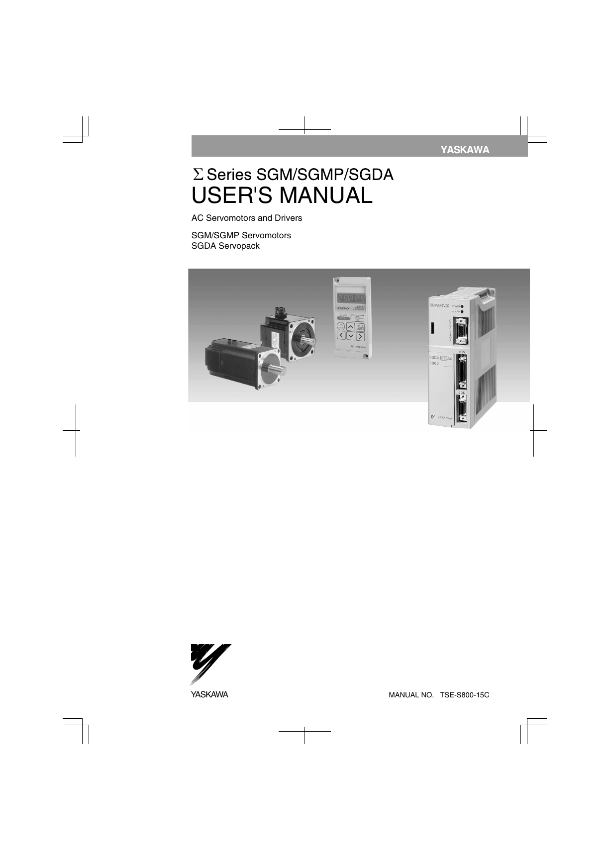
YASKAWA USER'S MANUAL AC Servomotors and Drivers SGM/SGMP Servomotors SGDA Servopack YASKAWA MANUAL NO. TSE-S800-15C
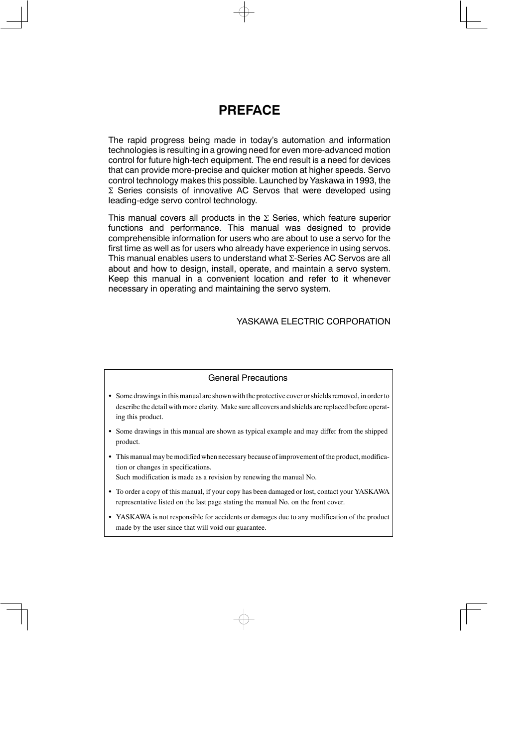
PREFACE The rapid progress being made in today’s automation and information technologies is resulting in a growing need for even more-advanced motion control for future high-tech equipment. The end result is a need for devices that can provide more-precise and quicker motion at higher speeds. Servo control technology makes this possible. Launched by Yaskawa in 1993, the Σ Series consists of innovative AC Servos that were developed using leading-edge servo control technology. This manual covers all products in the Σ Series, which feature superior functions and performance. This manual was designed to provide comprehensible information for users who are about to use a servo for the first time as well as for users who already have experience in using servos. This manual enables users to understand what Σ-Series AC Servos are all about and how to design, install, operate, and maintain a servo system. Keep this manual location and refer to it whenever necessary in operating and maintaining the servo system. in a convenient YASKAWA ELECTRIC CORPORATION General Precautions S Some drawings in this manual are shown with the protective cover or shields removed, in order to describe the detail with more clarity. Make sure all covers and shields are replaced before operat- ing this product. S Some drawings in this manual are shown as typical example and may differ from the shipped product. S This manual may be modified when necessary because of improvement of the product, modifica- tion or changes in specifications. Such modification is made as a revision by renewing the manual No. S To order a copy of this manual, if your copy has been damaged or lost, contact your YASKAWA representative listed on the last page stating the manual No. on the front cover. S YASKAWA is not responsible for accidents or damages due to any modification of the product made by the user since that will void our guarantee.
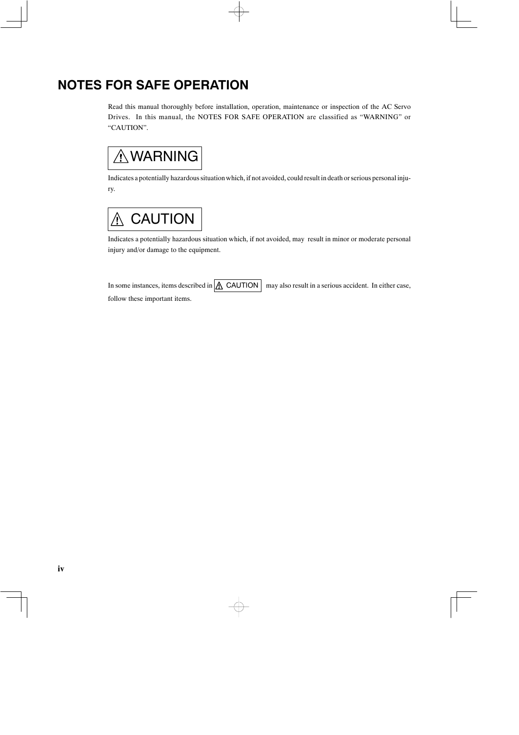
NOTES FOR SAFE OPERATION Read this manual thoroughly before installation, operation, maintenance or inspection of the AC Servo Drives. In this manual, the NOTES FOR SAFE OPERATION are classified as “WARNING” or “CAUTION”. WARNING Indicates a potentially hazardous situation which, if not avoided, could result in death or serious personal inju- ry. CAUTION Indicates a potentially hazardous situation which, if not avoided, may result in minor or moderate personal injury and/or damage to the equipment. In some instances, items described in CAUTION may also result in a serious accident. In either case, follow these important items. iv
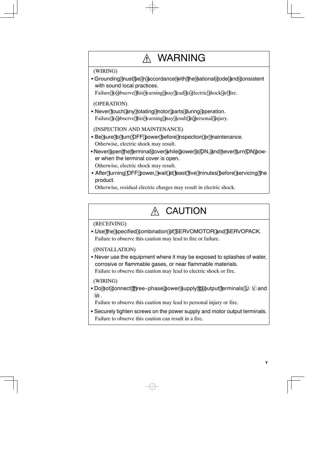
WARNING (WIRING) S Grounding must be in accordance with the national code and consistent with sound local practices. Failure to observe this warning may lead to electric shock or fire. (OPERATION) S Never touch any rotating motor parts during operation. Failure to observe this warning may result in personal injury. (INSPECTION AND MAINTENANCE) S Be sure to turn OFF power before inspection or maintenance. Otherwise, electric shock may result. S Never open the terminal cover while power is ON, and never turn ON pow- er when the terminal cover is open. Otherwise, electric shock may result. S After turning OFF power, wait at least five minutes before servicing the product. Otherwise, residual electric charges may result in electric shock. CAUTION (RECEIVING) S Use the specified combination of SERVOMOTOR and SERVOPACK. Failure to observe this caution may lead to fire or failure. (INSTALLATION) S Never use the equipment where it may be exposed to splashes of water, corrosive or flammable gases, or near flammable materials. Failure to observe this caution may lead to electric shock or fire. (WIRING) S Do not connect t hree−phase power supply t o output terminals UV and W . Failure to observe this caution may lead to personal injury or fire. S Securely tighten screws on the power supply and motor output terminals. Failure to observe this caution can result in a fire. v
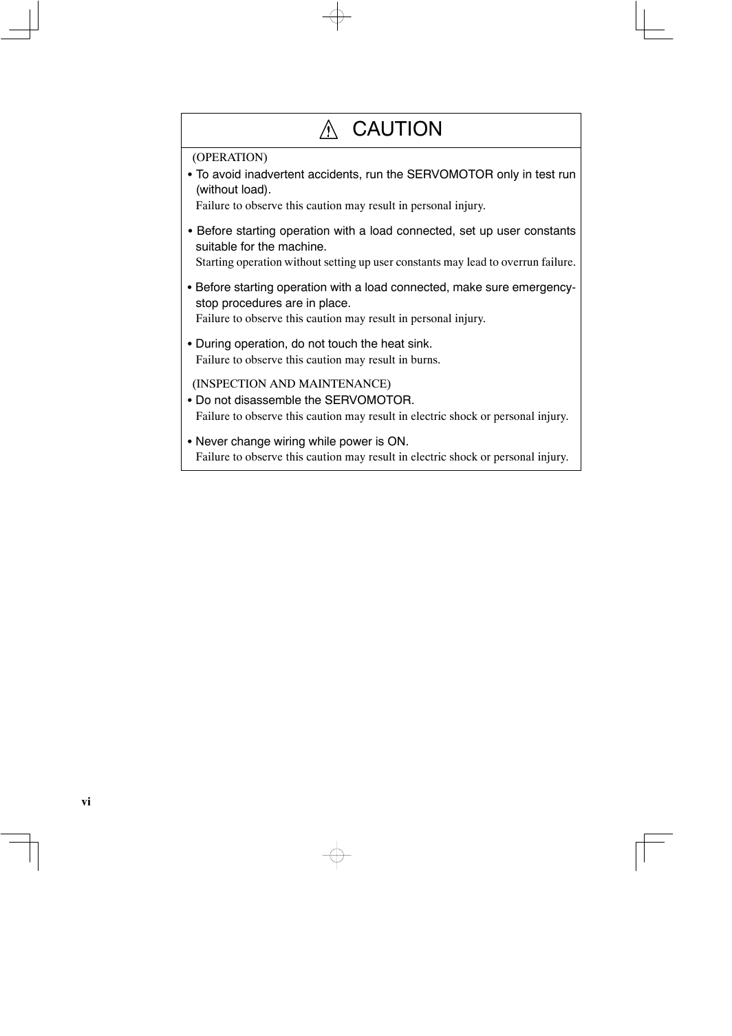
CAUTION (OPERATION) S To avoid inadvertent accidents, run the SERVOMOTOR only in test run (without load). Failure to observe this caution may result in personal injury. S Before starting operation with a load connected, set up user constants suitable for the machine. Starting operation without setting up user constants may lead to overrun failure. S Before starting operation with a load connected, make sure emergency- stop procedures are in place. Failure to observe this caution may result in personal injury. S During operation, do not touch the heat sink. Failure to observe this caution may result in burns. (INSPECTION AND MAINTENANCE) S Do not disassemble the SERVOMOTOR. Failure to observe this caution may result in electric shock or personal injury. S Never change wiring while power is ON. Failure to observe this caution may result in electric shock or personal injury. vi
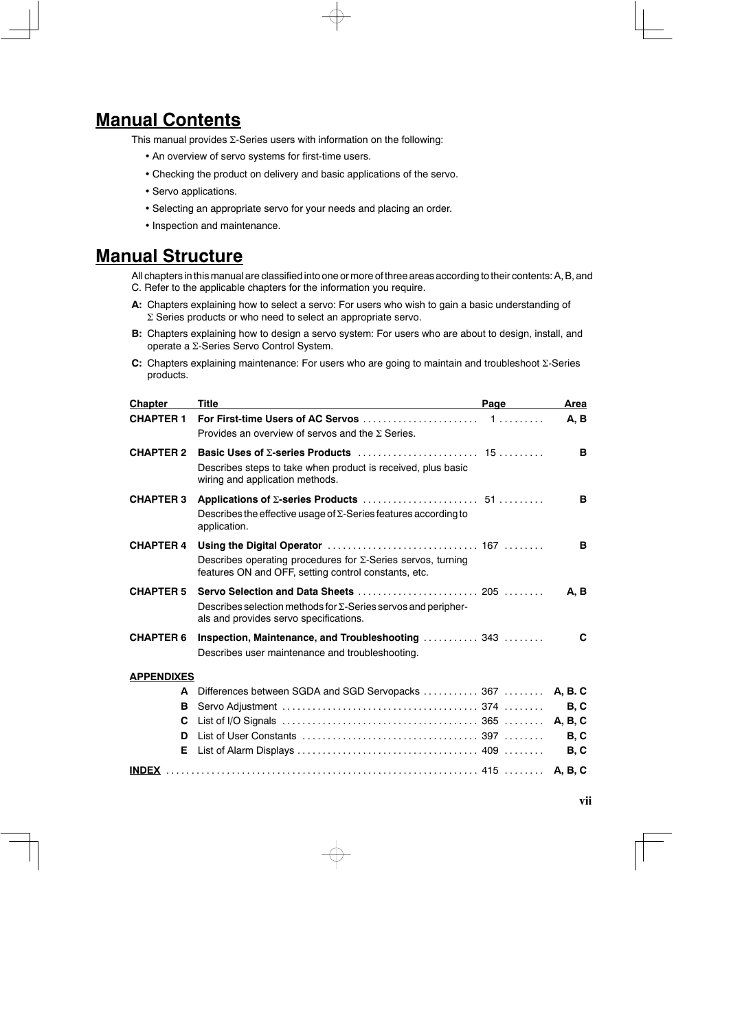
Manual Contents This manual provides Σ-Series users with information on the following: • An overview of servo systems for first-time users. • Checking the product on delivery and basic applications of the servo. • Servo applications. • Selecting an appropriate servo for your needs and placing an order. • Inspection and maintenance. Manual Structure All chapters in this manual are classified into one or more of three areas according to their contents: A, B, and C. Refer to the applicable chapters for the information you require. A: Chapters explaining how to select a servo: For users who wish to gain a basic understanding of Σ Series products or who need to select an appropriate servo. B: Chapters explaining how to design a servo system: For users who are about to design, install, and operate a Σ-Series Servo Control System. C: Chapters explaining maintenance: For users who are going to maintain and troubleshoot Σ-Series products. Chapter CHAPTER 1 For First-time Users of AC Servos Title . . . . . . . . . . . . . . . . . . . . . . . 1 . . . . . . . . . Page Provides an overview of servos and the Σ Series. CHAPTER 2 Basic Uses of Σ-series Products . . . . . . . . . . . . . . . . . . . . . . . . 15 . . . . . . . . . Describes steps to take when product is received, plus basic wiring and application methods. CHAPTER 3 Applications of Σ-series Products . . . . . . . . . . . . . . . . . . . . . . . 51 . . . . . . . . . Describes the effective usage of Σ-Series features according to application. CHAPTER 4 Using the Digital Operator . . . . . . . . . . . . . . . . . . . . . . . . . . . . . . 167 . . . . . . . . Area A, B B B B Describes operating procedures for Σ-Series servos, turning features ON and OFF, setting control constants, etc. CHAPTER 5 Servo Selection and Data Sheets . . . . . . . . . . . . . . . . . . . . . . . . 205 . . . . . . . . A, B Describes selection methods for Σ-Series servos and peripher- als and provides servo specifications. CHAPTER 6 Inspection, Maintenance, and Troubleshooting Describes user maintenance and troubleshooting. . . . . . . . . . . . 343 . . . . . . . . C APPENDIXES A Differences between SGDA and SGD Servopacks B Servo Adjustment C List of I/O Signals D List of User Constants E List of Alarm Displays . . . . . . . . . . . . . . . . . . . . . . . . . . . . . . . . . . . . . . . . . . . . . . . . . . . . . . . . . . . . . . . . . . . . . . . . . . . . . . . . . . . . . . . . . . . . . . . . . . . . . . . . . . . . . . . . . . . . . . . . . . . . . . . . . . . . . . . . . . . . . . . . . . . . . . . . . . . . . . . . 367 374 365 397 409 . . . . . . . . . . . . . . . . . . . . . . . . . . . . . . . . . . . . . . . . A, B. C B, C A, B, C B, C B, C INDEX . . . . . . . . . . . . . . . . . . . . . . . . . . . . . . . . . . . . . . . . . . . . . . . . . . . . . . . . . . . . . . 415 . . . . . . . . A, B, C vii
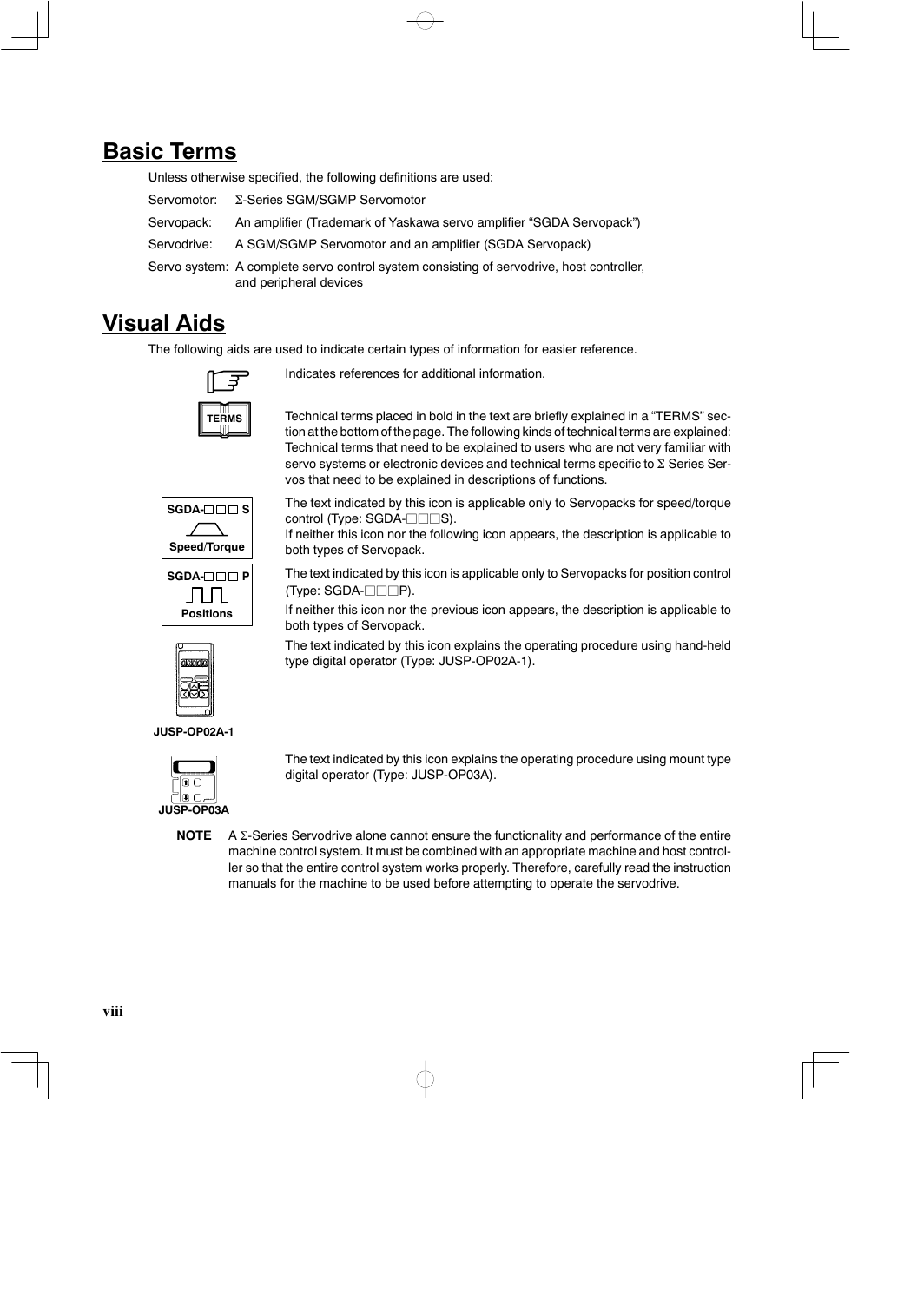
Basic Terms Unless otherwise specified, the following definitions are used: Servomotor: Servopack: Servodrive: Servo system: A complete servo control system consisting of servodrive, host controller, Σ-Series SGM/SGMP Servomotor An amplifier (Trademark of Yaskawa servo amplifier “SGDA Servopack”) A SGM/SGMP Servomotor and an amplifier (SGDA Servopack) and peripheral devices Visual Aids The following aids are used to indicate certain types of information for easier reference. Indicates references for additional information. . TERMS SGDA- S Speed/Torque SGDA- P Positions Technical terms placed in bold in the text are briefly explained in a “TERMS” sec- tion at the bottom of the page. The following kinds of technical terms are explained: Technical terms that need to be explained to users who are not very familiar with servo systems or electronic devices and technical terms specific to Σ Series Ser- vos that need to be explained in descriptions of functions. The text indicated by this icon is applicable only to Servopacks for speed/torque control (Type: SGDA-jjjS). If neither this icon nor the following icon appears, the description is applicable to both types of Servopack. The text indicated by this icon is applicable only to Servopacks for position control (Type: SGDA-jjjP). If neither this icon nor the previous icon appears, the description is applicable to both types of Servopack. The text indicated by this icon explains the operating procedure using hand-held type digital operator (Type: JUSP-OP02A-1). JUSP-OP02A-1 JUSP-OP03A The text indicated by this icon explains the operating procedure using mount type digital operator (Type: JUSP-OP03A). NOTE A Σ-Series Servodrive alone cannot ensure the functionality and performance of the entire machine control system. It must be combined with an appropriate machine and host control- ler so that the entire control system works properly. Therefore, carefully read the instruction manuals for the machine to be used before attempting to operate the servodrive. viii
Yaskawa, 1995 All rights reserved. No part of this publication may be reproduced, stored in a retrieval system, or transmitted, in any form, or by any means, mechanical, electronic, photocopying, recording, or otherwise, without the prior written permission of Yas- kawa. No patent liability is assumed with respect to the use of the information contained herein. Moreover, because Yaskawa is constantly striving to improve its high-quality products, the information contained in this manual is subject to change without notice. Every precaution has been taken in the preparation of this manual. Nevertheless, Yaskawa assumes no re- sponsibility for errors or omissions. Neither is any liability assumed for damages resulting from the use of the information contained in this publication. ix
分享到:
收藏