实验九 配置访问控制列表
一、标准 IP 访问控制列表配置
实验目标
理解标准 IP 访问控制列表的原理及功能
掌握编号的标准 IP 访问控制列表的配置方法
实验背景
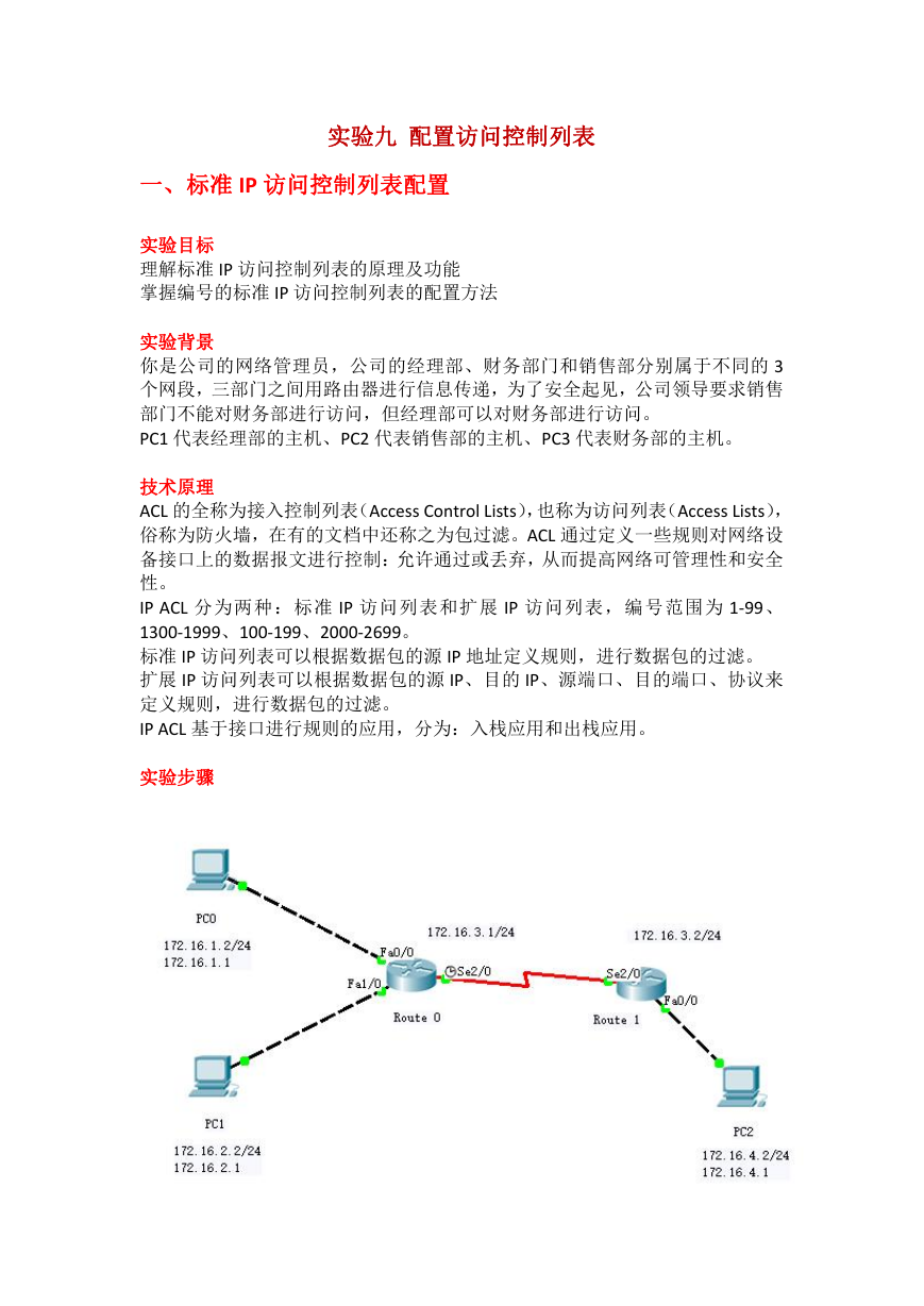
你是公司的网络管理员,公司的经理部、财务部门和销售部分别属于不同的 3
个网段,三部门之间用路由器进行信息传递,为了安全起见,公司领导要求销售
部门不能对财务部进行访问,但经理部可以对财务部进行访问。
PC1 代表经理部的主机、PC2 代表销售部的主机、PC3 代表财务部的主机。
技术原理
ACL 的全称为接入控制列表(Access Control Lists),也称为访问列表(Access Lists),
俗称为防火墙,在有的文档中还称之为包过滤。ACL 通过定义一些规则对网络设
备接口上的数据报文进行控制:允许通过或丢弃,从而提高网络可管理性和安全
性。
IP ACL 分为两种:标准 IP 访问列表和扩展 IP 访问列表,编号范围为 1-99、
1300-1999、100-199、2000-2699。
标准 IP 访问列表可以根据数据包的源 IP 地址定义规则,进行数据包的过滤。
扩展 IP 访问列表可以根据数据包的源 IP、目的 IP、源端口、目的端口、协议来
定义规则,进行数据包的过滤。
IP ACL 基于接口进行规则的应用,分为:入栈应用和出栈应用。
实验步骤
�
(1)路由器之间通过串口连接,DCE 端连接在 R1 上,配置其时钟频率 64000;
主机与路由器通过交叉线连接。
(2)配置路由器接口 IP 地址。
(3)在路由器上配置静态路由协议,让三台 PC 能相互 ping 通,因为只有在互
通的前提下才能涉及到访问控制列表。
(4)在 R1 上配置编号的 IP 标准访问控制
(5)将标准 IP 访问列表应用到接口上。
(6)验证主机之间的互通性。
End with CNTL/Z.
Route 0
Router>en
Router#conf t
Enter configuration commands, one per line.
Router(config)#hostname R0
R0(config)#int fa 0/0
R0(config-if)#ip address 172.16.1.1 255.255.255.0
R0(config-if)#no shutdown
R0(config)#int fa 1/0
R0(config-if)#ip address 172.16.2.1 255.255.255.0
R0(config-if)#no shutdown
R0(config-if)#int s 2/0
R0(config-if)#ip address 172.16.3.1 255.255.255.0
R0(config-if)#no shutdown
R0(config-if)#clock rate 64000
R0(config-if)#exit
R0(config)#ip route 172.16.4.0 255.255.255.0 172.16.3.2
R0(config)#ip access-list standard cmx
R0(config-std-nacl)#permit 172.16.1.0 0.0.0.255
R0(config-std-nacl)#deny 172.16.2.0 0.0.0.255
R0(config-std-nacl)#end
R0#
%SYS-5-CONFIG_I: Configured from console by console
R0#conf t
R0(config)#int s2/0
R0(config-if)#ip access-group cmx outbound
端口到互联网
R0(config-if)#end
//outbound 为路由器的数据通过此
�
Route 1
Router>en
Router#conf t
Enter configuration commands, one per line.
Router(config)#hostname R1
R1(config)#int s 2/0
R1(config-if)#ip address 172.16.3.2 255.255.255.0
R1(config-if)#no shutdown
R1(config-if)#int fa 0/0
R1(config-if)#ip address 172.16.4.1 255.255.255.0
R1(config-if)#no shutdown
End with CNTL/Z.
R1(config-if)#exit
R1(config)#ip route 0.0.0.0 0.0.0.0 172.16.3.1
R1(config)#end
R1#
%SYS-5-CONFIG_I: Configured from console by console
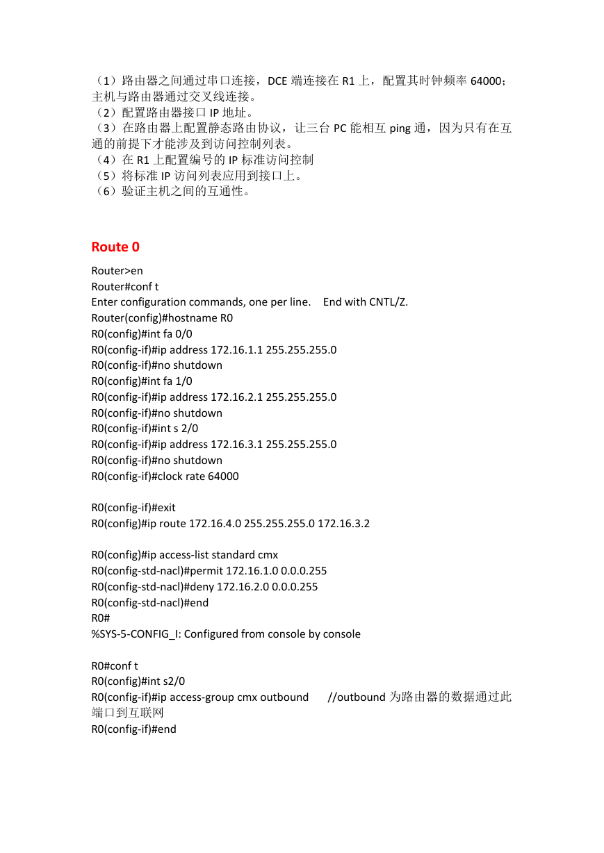
R1#show ip route
Codes: C - connected, S - static, I - IGRP, R - RIP, M - mobile, B - BGP
D - EIGRP, EX - EIGRP external, O - OSPF, IA - OSPF inter area
N1 - OSPF NSSA external type 1, N2 - OSPF NSSA external type 2
E1 - OSPF external type 1, E2 - OSPF external type 2, E - EGP
i - IS-IS, L1 - IS-IS level-1, L2 - IS-IS level-2, ia - IS-IS inter area
* - candidate default, U - per-user static route, o - ODR
P - periodic downloaded static route
Gateway of last resort is 172.16.3.1 to network 0.0.0.0
172.16.0.0/24 is subnetted, 2 subnets
172.16.3.0 is directly connected, Serial2/0
172.16.4.0 is directly connected, FastEthernet0/0
0.0.0.0/0 [1/0] via 172.16.3.1
C
C
S*
�
PC0
PC1
�
PC2
验证:
PC0 可以 ping 通 172.16.4.2,PC1 则 ping 不通。
�
二、扩展 IP 访问控制列表配置
技术原理
访问列表中定义的典型规则主要有以下:源地址、目标地址、上层协议
、时间区域;
扩展 IP 访问列表(编号为 100-199,2000-2699)使用以上四种组合来进行转
发或阻断分组;可以根据数据包的源 IP、目的 IP、源端口、目的端口、协议来定
义规则,进行数据包的过滤。
扩展 IP 访问列表的配置包括以下两步:
(1)定义扩展 IP 访问列表
(2)将扩展 IP 访问列表应用于特定接口上
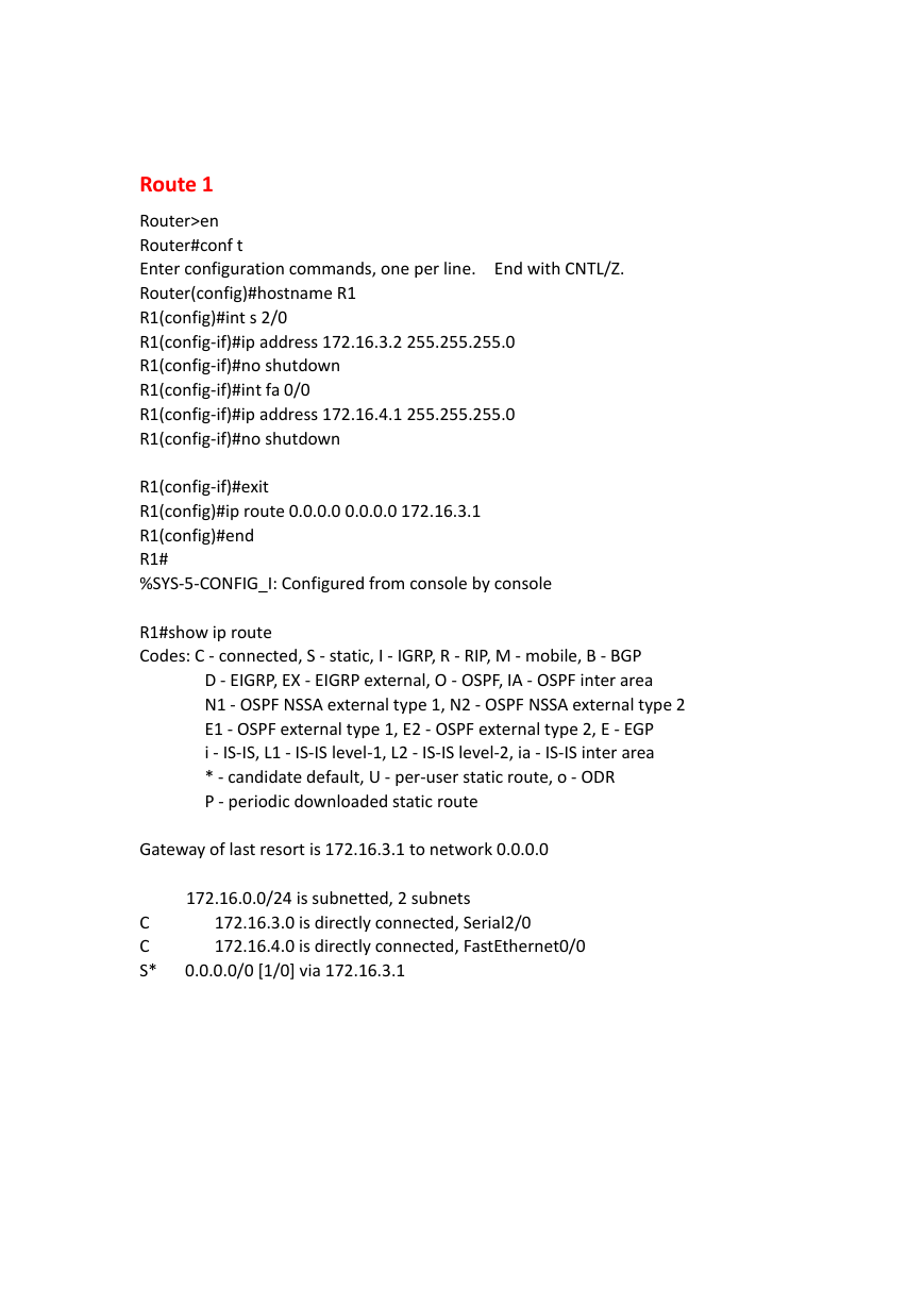
实验步骤
(1)分公司出口路由器与外部路由器之间通过串口连接,DCE 端连接在 R2 上,
配置其时钟频率 64000;主机与路由器通过交叉线连接。
(2)配置 PC 机、服务器及路由器接口 IP 地址。
(3)在各路由器配置静态路由协议,让 PC 间能相互 ping 通,因为只有在互通
的前提下才能涉及到访问控制列表。
(4)在 R2 上配置编号的 IP 扩展访问控制列表。
(5)将扩展 IP 访问列表应用到接口上。
(6)验证主机之间的互通性。
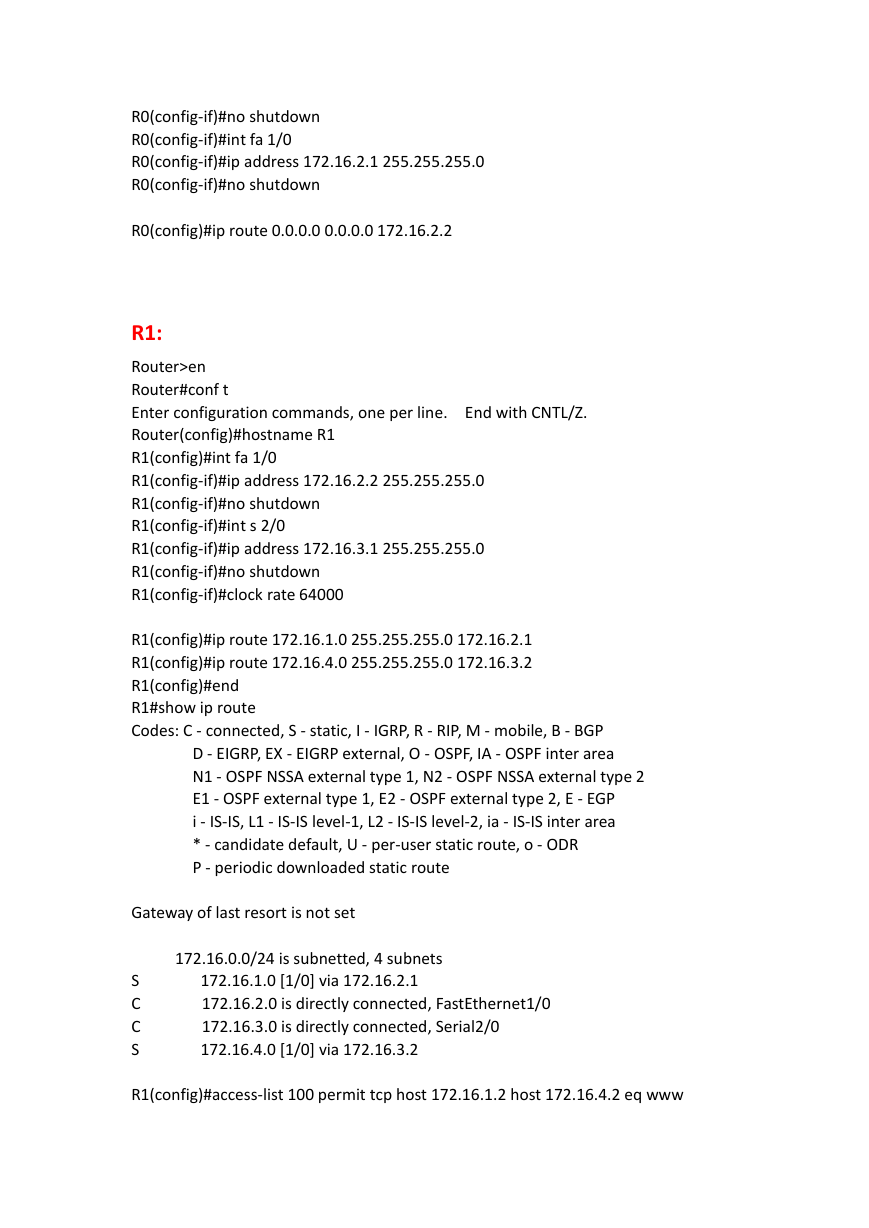
R0:
Router>en
Router#conf t
Enter configuration commands, one per line.
Router(config)#hostname R0
R0(config)#int fa 0/0
R0(config-if)#ip address 172.16.1.1 255.255.255.0
End with CNTL/Z.
�
R0(config-if)#no shutdown
R0(config-if)#int fa 1/0
R0(config-if)#ip address 172.16.2.1 255.255.255.0
R0(config-if)#no shutdown
R0(config)#ip route 0.0.0.0 0.0.0.0 172.16.2.2
R1:
Router>en
Router#conf t
Enter configuration commands, one per line.
Router(config)#hostname R1
R1(config)#int fa 1/0
R1(config-if)#ip address 172.16.2.2 255.255.255.0
R1(config-if)#no shutdown
R1(config-if)#int s 2/0
R1(config-if)#ip address 172.16.3.1 255.255.255.0
R1(config-if)#no shutdown
R1(config-if)#clock rate 64000
End with CNTL/Z.
R1(config)#ip route 172.16.1.0 255.255.255.0 172.16.2.1
R1(config)#ip route 172.16.4.0 255.255.255.0 172.16.3.2
R1(config)#end
R1#show ip route
Codes: C - connected, S - static, I - IGRP, R - RIP, M - mobile, B - BGP
D - EIGRP, EX - EIGRP external, O - OSPF, IA - OSPF inter area
N1 - OSPF NSSA external type 1, N2 - OSPF NSSA external type 2
E1 - OSPF external type 1, E2 - OSPF external type 2, E - EGP
i - IS-IS, L1 - IS-IS level-1, L2 - IS-IS level-2, ia - IS-IS inter area
* - candidate default, U - per-user static route, o - ODR
P - periodic downloaded static route
Gateway of last resort is not set
172.16.0.0/24 is subnetted, 4 subnets
172.16.1.0 [1/0] via 172.16.2.1
172.16.2.0 is directly connected, FastEthernet1/0
172.16.3.0 is directly connected, Serial2/0
172.16.4.0 [1/0] via 172.16.3.2
S
C
C
S
R1(config)#access-list 100 permit tcp host 172.16.1.2 host 172.16.4.2 eq www
�
R1(config)#access-list 100 deny icmp host 172.16.1.2 host 172.16.4.2 echo
R1(config)#int s 2/0
R1(config-if)#ip access-group 100 out
R1(config-if)#end
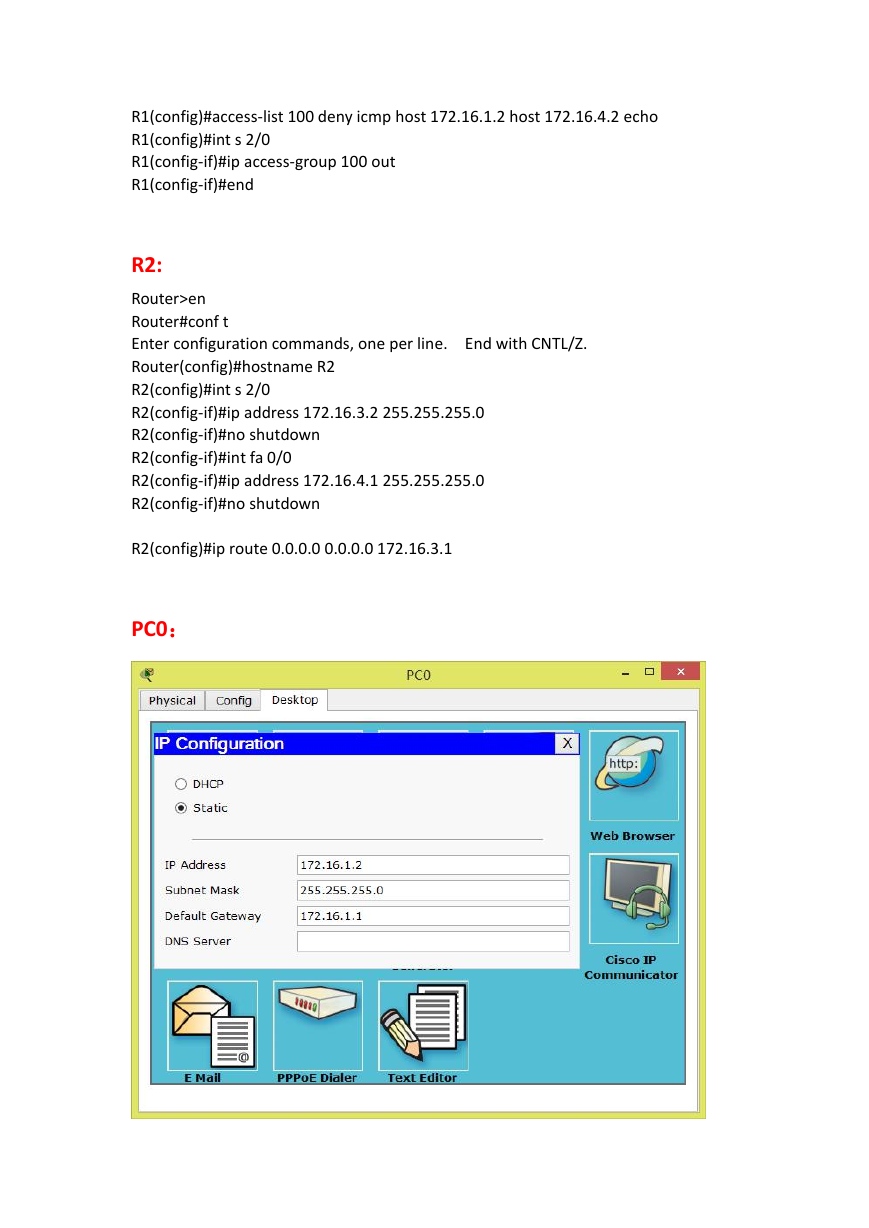
R2:
Router>en
Router#conf t
Enter configuration commands, one per line.
Router(config)#hostname R2
R2(config)#int s 2/0
R2(config-if)#ip address 172.16.3.2 255.255.255.0
R2(config-if)#no shutdown
R2(config-if)#int fa 0/0
R2(config-if)#ip address 172.16.4.1 255.255.255.0
R2(config-if)#no shutdown
End with CNTL/Z.
R2(config)#ip route 0.0.0.0 0.0.0.0 172.16.3.1
PC0:
�




 2023年江西萍乡中考道德与法治真题及答案.doc
 2012年重庆南川中考生物真题及答案.doc
 2013年江西师范大学地理学综合及文艺理论基础考研真题.doc
 2020年四川甘孜小升初语文真题及答案I卷.doc
 2020年注册岩土工程师专业基础考试真题及答案.doc
 2023-2024学年福建省厦门市九年级上学期数学月考试题及答案.doc
 2021-2022学年辽宁省沈阳市大东区九年级上学期语文期末试题及答案.doc
 2022-2023学年北京东城区初三第一学期物理期末试卷及答案.doc
 2018上半年江西教师资格初中地理学科知识与教学能力真题及答案.doc
 2012年河北国家公务员申论考试真题及答案-省级.doc
 2020-2021学年江苏省扬州市江都区邵樊片九年级上学期数学第一次质量检测试题及答案.doc
 2022下半年黑龙江教师资格证中学综合素质真题及答案.doc