logo资料库

USB Type-C Spec R2.0 - August 2019.pdf

第1页 / 共373页
第2页 / 共373页
第3页 / 共373页
第4页 / 共373页
第5页 / 共373页
第6页 / 共373页
第7页 / 共373页
第8页 / 共373页
资料共373页,剩余部分请下载后查看
Specification Work Group Chairs / Specification Editors
Specification Work Group Contributors
Pre-Release Draft Industry Reviewing Companies That Provided Feedback
Revision History
1 Introduction
1.1 Purpose
1.2 Scope
1.3 Related Documents
1.4 Conventions
1.4.1 Precedence
1.4.2 Keywords
1.4.2.1 Informative
1.4.2.2 May
1.4.2.3 N/A
1.4.2.4 Normative
1.4.2.5 Optional
1.4.2.6 Reserved
1.4.2.7 Shall
1.4.2.8 Should
1.4.3 Numbering
1.5 Terms and Abbreviations
2 Overview
2.1 Introduction
2.2 USB Type-C Receptacles, Plugs and Cables
2.3 Configuration Process
2.3.1 Source-to-Sink Attach/Detach Detection
2.3.2 Plug Orientation/Cable Twist Detection
2.3.3 Initial Power (Source-to-Sink) Detection and Establishing the Data (Host-to-Device) Relationship
2.3.4 USB Type-C Vbus Current Detection and Usage
2.3.5 USB PD Communication
2.3.6 Functional Extensions
2.4 Vbus
2.5 Vconn
2.6 Hubs
3 Mechanical
3.1 Overview
3.1.1 Compliant Connectors
3.1.2 Compliant Cable Assemblies
3.1.3 Compliant USB Type-C to Legacy Cable Assemblies
3.1.4 Compliant USB Type-C to Legacy Adapter Assemblies
3.2 USB Type-C Connector Mating Interfaces
3.2.1 Interface Definition
3.2.2 Reference Designs
3.2.2.1 Receptacle Mid-Plate (Informative)
3.2.2.2 Side Latch (informative)
3.2.2.3 Internal EMC Springs and Pads (Informative)
3.2.2.4 Optional External Receptacle EMC Springs (Informative)
3.2.2.5 USB Full-Featured Type-C Plug Paddle Card (Informative)
3.2.3 Pin Assignments and Descriptions
3.3 Cable Construction and Wire Assignments
3.3.1 Cable Construction (Informative)
3.3.2 Wire Assignments
3.3.3 Wire Gauges and Cable Diameters (Informative)
3.4 Standard USB Type-C Cable Assemblies
3.4.1 USB Full-Featured Type-C Cable Assembly
3.4.2 USB 2.0 Type-C Cable Assembly
3.4.3 USB Type-C Captive Cable Assemblies
3.5 Legacy Cable Assemblies
3.5.1 USB Type-C to USB 3.1 Standard-A Cable Assembly
3.5.2 USB Type-C to USB 2.0 Standard-A Cable Assembly
3.5.3 USB Type-C to USB 3.1 Standard-B Cable Assembly
3.5.4 USB Type-C to USB 2.0 Standard-B Cable Assembly
3.5.5 USB Type-C to USB 2.0 Mini-B Cable Assembly
3.5.6 USB Type-C to USB 3.1 Micro-B Cable Assembly
3.5.7 USB Type-C to USB 2.0 Micro-B Cable Assembly
3.6 Legacy Adapter Assemblies
3.6.1 USB Type-C to USB 3.1 Standard-A Receptacle Adapter Assembly
3.6.2 USB Type-C to USB 2.0 Micro-B Receptacle Adapter Assembly
3.7 Electrical Characteristics
3.7.1 Raw Cable (Informative)
3.7.1.1 Intra-Pair Skew (Informative)
3.7.1.2 Differential Insertion Loss (Informative)
3.7.2 USB Type-C to Type-C Passive Cable Assemblies (Normative)
3.7.2.1 Recommended TX/RX Passive Cable Assembly Characteristics (USB 3.2 Gen2 and USB4 Gen2)
3.7.2.1.1 Differential Insertion Loss (Informative – USB 3.2 Gen2 and USB4 Gen2)
3.7.2.1.2 Differential Return Loss (Informative – USB 3.2 Gen2 and USB4 Gen2)
3.7.2.1.3 Differential Near-End and Far-End Crosstalk between TX/RX Pairs (Informative – USB 3.2 Gen2 and USB4 Gen2)
3.7.2.1.4 Differential Crosstalk between USB D+/D− and TX/RX Pairs (Informative – USB 3.2 Gen2 and USB4 Gen2)
3.7.2.2 Recommended TX/RX Passive Cable Assembly Characteristics (USB4 Gen3)
3.7.2.2.1 Differential Insertion Loss (Informative – USB4 Gen3)
3.7.2.2.2 Differential Return Loss (Informative – USB4 Gen3)
3.7.2.2.3 Differential Near-End and Far-End Crosstalk between TX/RX Pairs (Informative – USB4 Gen3)
3.7.2.2.4 Differential Crosstalk between USB D+/D− and TX/RX Pairs (Informative – USB4 Gen3)
3.7.2.3 Normative TX/RX Passive Cable Assembly Requirements (USB 3.2 Gen2 and USB4 Gen2)
3.7.2.3.1 Insertion Loss Fit at Nyquist Frequencies (Normative – USB 3.2 Gen2 and USB4 Gen2)
3.7.2.3.2 Integrated Multi-reflection (Normative – USB 3.2 Gen2 and USB4 Gen2)
3.7.2.3.3 Integrated Crosstalk between TX/RX Pairs (Normative – USB 3.2 Gen2 and USB4 Gen2)
3.7.2.3.4 Integrated Crosstalk between TX/RX Pairs to USB 2.0 D+/D− (Normative – USB 3.2 Gen2 and USB4 Gen2)
3.7.2.3.5 Integrated Return Loss (Normative – USB 3.2 Gen2 and USB4 Gen2)
3.7.2.3.6 Differential-to-Common-Mode Conversion (Normative – USB 3.2 Gen2 and USB4 Gen2)
3.7.2.4 Normative TX/RX Passive Cable Assembly Requirements (USB4 Gen3)
3.7.2.4.1 Insertion Loss Fit at Nyquist Frequencies (Normative – USB4 Gen3)
3.7.2.4.2 Integrated Multi-Reflection (Informative – USB4 Gen3)
3.7.2.4.3 Integrated Crosstalk between TX/RX Pairs (Normative – USB4 Gen3)
3.7.2.4.4 Integrated Crosstalk from TX/RX Pairs to USB 2.0 D+/D− (Normative – USB4 Gen3)
3.7.2.4.5 Integrated Return Loss (Normative – USB4 Gen3)
3.7.2.4.6 Differential-to-Common-Mode Conversion (Normative – USB4 Gen3)
3.7.2.4.7 COM Requirement (Normative – USB4 Gen3)
3.7.2.5 Low-Speed Signal Requirements (Normative)
3.7.2.5.1 CC to USB D+/D− (Normative)
3.7.2.5.2 Vbus Coupling to SBU_A/SBU_B, CC, and USB D+/D− (Normative)
3.7.2.5.3 Coupling between SBU_A and SBU_B (Normative)
3.7.2.5.4 Coupling between SBU_A/SBU_B and CC (Normative)
3.7.2.5.5 Coupling between SBU_A/SBU_B and USB D+/D− (Normative)
3.7.2.6 USB D+/D− Signal Requirements (Normative)
3.7.2.7 Vbus DC Voltage Tolerance (Normative)
3.7.3 Mated Connector (Informative – USB 3.2 Gen2 and USB4 Gen2)
3.7.3.1 Differential Impedance (Informative)
3.7.3.2 Mated Connector Recommended Differential S-Parameter and Signal Integrity Characteristics (Informative)
3.7.4 Mated Connector (Normative – USB4 Gen3)
3.7.5 USB Type-C to Legacy Cable Assemblies (Normative)
3.7.5.1 USB 2.0-only Cable Assemblies (Normative)
3.7.5.2 USB 3.1 Gen2 Cable Assemblies (Normative)
3.7.5.3 Compliant USB Legacy Plugs used in USB Type-C to Legacy Cable Assemblies
3.7.5.3.1 Contact Material Requirements for USB Type-C to USB Micro-B Assemblies
3.7.5.3.2 Contact Current Ratings for USB Standard-A, USB Standard-B and USB Micro-B Connector Mated Pairs (EIA 364-70, Method 2)
3.7.6 USB Type-C to USB Legacy Adapter Assemblies (Normative)
3.7.6.1 USB 2.0 Type-C Plug to USB 2.0 Micro-B Receptacle Adapter Assembly (Normative)
3.7.6.2 USB Full-Featured Type-C Plug to USB 3.1 Standard-A Receptacle Adapter Assembly (Normative)
3.7.6.3 Compliant USB Legacy Receptacles used in USB Type-C to Legacy Adapter Assemblies
3.7.6.3.1 Contact Material Requirements
3.7.6.3.2 Contact Current Ratings
3.7.7 Shielding Effectiveness Requirements (Normative)
3.7.8 DC Electrical Requirements (Normative)
3.7.8.1 Low Level Contact Resistance (EIA 364-23B)
3.7.8.2 Dielectric Strength (EIA 364-20)
3.7.8.3 Insulation Resistance (EIA 364-21)
3.7.8.4 Contact Current Rating
3.7.8.5 DC Resistance of D+ and D−
3.8 Mechanical and Environmental Requirements (Normative)
3.8.1 Mechanical Requirements
3.8.1.1 Insertion Force (EIA 364-13)
3.8.1.2 Extraction Force (EIA 364-13)
3.8.1.3 Durability or Insertion/Extraction Cycles (EIA 364-09)
3.8.1.4 Cable Flexing (EIA 364-41, Condition 1)
3.8.1.5 Cable Pull-Out (EIA 364-38, Method A)
3.8.1.6 4-Axis Continuity Test
3.8.1.7 Wrenching Strength
3.8.1.8 Restriction of Hazardous Substances
3.8.2 Environmental Requirements
3.8.2.1 Reference Materials (Informative)
3.9 Docking Applications (Informative)
3.10 Implementation Notes and Design Guides
3.10.1 EMC Management (Informative)
3.10.2 Stacked and Side-by-Side Connector Physical Spacing (Informative)
3.10.3 Cable Mating Considerations (Informative)
4 Functional
4.1 Signal Summary
4.2 Signal Pin Descriptions
4.2.1 SuperSpeed USB Pins
4.2.2 USB 2.0 Pins
4.2.3 Auxiliary Signal Pins
4.2.4 Power and Ground Pins
4.2.5 Configuration Pins
4.3 Sideband Use (SBU)
4.4 Power and Ground
4.4.1 IR Drop
4.4.2 Vbus
4.4.3 Vconn
4.5 Configuration Channel (CC)
4.5.1 Architectural Overview
4.5.1.1 USB Data Bus Interface and USB Type-C Plug Flip-ability
4.5.1.2 Connecting Sources and Sinks
4.5.1.2.1 Detecting a Valid Source-to-Sink Connection
4.5.1.3 Configuration Channel Functional Models
4.5.1.3.1 Source Configuration Channel Functional Model
4.5.1.3.2 Sink Configuration Channel Functional Model
4.5.1.3.3 Dual-Role-Power (DRP) Configuration Channel Functional Model
4.5.1.4 USB Type-C Port Power Roles and Role Swapping Mechanisms
4.5.1.4.1 USB Type-C State-Machine-Based Role Swapping
4.5.1.4.2 USB PD-based Power Role, Data Role and Vconn Swapping
4.5.1.4.3 Power Role Behavioral Model Summary
4.5.2 CC Functional and Behavioral Requirements
4.5.2.1 Connection State Diagrams
4.5.2.2 Connection State Machine Requirements
4.5.2.2.1 Disabled State
4.5.2.2.1.1 Disabled State Requirements
4.5.2.2.1.2 Exiting From Disabled State
4.5.2.2.2 ErrorRecovery State
4.5.2.2.2.1 ErrorRecovery State Requirements
4.5.2.2.2.2 Exiting From ErrorRecovery State
4.5.2.2.3 Unattached.SNK State
4.5.2.2.3.1 Unattached.SNK Requirements
4.5.2.2.3.2 Exiting from Unattached.SNK State
4.5.2.2.4 AttachWait.SNK State
4.5.2.2.4.1 AttachWait.SNK Requirements
4.5.2.2.4.2 Exiting from AttachWait.SNK State
4.5.2.2.5 Attached.SNK State
4.5.2.2.5.1 Attached.SNK Requirements
4.5.2.2.5.2 Exiting from Attached.SNK State
4.5.2.2.6 UnattachedWait.SRC State
4.5.2.2.6.1 UnattachedWait.SRC Requirements
4.5.2.2.6.2 Exiting from UnattachedWait.SRC State
4.5.2.2.7 Unattached.SRC State
4.5.2.2.7.1 Unattached.SRC Requirements
4.5.2.2.7.2 Exiting from Unattached.SRC State
4.5.2.2.8 AttachWait.SRC State
4.5.2.2.8.1 AttachWait.SRC Requirements
4.5.2.2.8.2 Exiting from AttachWait.SRC State
4.5.2.2.9 Attached.SRC State
4.5.2.2.9.1 Attached.SRC Requirements
4.5.2.2.9.2 Exiting from Attached.SRC State
4.5.2.2.10 Try.SRC State
4.5.2.2.10.1 Try.SRC Requirements
4.5.2.2.10.2 Exiting from Try.SRC State
4.5.2.2.11 TryWait.SNK State
4.5.2.2.11.1 TryWait.SNK Requirements
4.5.2.2.11.2 Exiting from TryWait.SNK State
4.5.2.2.12 Try.SNK State
4.5.2.2.12.1 Try.SNK Requirements
4.5.2.2.12.2 Exiting from Try.SNK State
4.5.2.2.13 TryWait.SRC State
4.5.2.2.13.1 TryWait.SRC Requirements
4.5.2.2.13.2 Exiting from TryWait.SRC State
4.5.2.2.14 Unattached.Accessory State
4.5.2.2.14.1 Unattached.Accessory Requirements
4.5.2.2.14.2 Exiting from Unattached.Accessory State
4.5.2.2.15 AttachWait.Accessory State
4.5.2.2.15.1 AttachWait.Accessory Requirements
4.5.2.2.15.2 Exiting from AttachWait.Accessory State
4.5.2.2.16 AudioAccessory State
4.5.2.2.16.1 AudioAccessory Requirements
4.5.2.2.16.2 Exiting from AudioAccessory State
4.5.2.2.17 UnorientedDebugAccessory.SRC
4.5.2.2.17.1 UnorientedDebugAccessory.SRC Requirements
4.5.2.2.17.2 Exiting from UnorientedDebugAccessory.SRC State
4.5.2.2.18 OrientedDebugAccessory.SRC State
4.5.2.2.18.1 OrientedDebugAccessory.SRC State Requirements
4.5.2.2.18.2 Exiting from OrientedDebugAccessory.SRC State
4.5.2.2.19 DebugAccessory.SNK
4.5.2.2.19.1 DebugAccessory.SNK Requirements
4.5.2.2.19.2 Exiting from DebugAccessory.SNK State
4.5.2.2.20 PoweredAccessory State
4.5.2.2.20.1 PoweredAccessory Requirements
4.5.2.2.20.2 Exiting from PoweredAccessory State
4.5.2.2.21 Unsupported.Accessory State
4.5.2.2.21.1 Unsupported.Accessory Requirements
4.5.2.2.21.2 Exiting from Unsupported.Accessory
4.5.2.2.22 CTUnattached.VPD State
4.5.2.2.22.1 CTUnattached.VPD Requirements
4.5.2.2.22.2 Exiting from CTUnattached.VPD
4.5.2.2.23 CTAttachWait.VPD State
4.5.2.2.23.1 CTAttachWait.VPD Requirements
4.5.2.2.23.2 Exiting from CTAttachWait.VPD
4.5.2.2.24 CTAttached.VPD State
4.5.2.2.24.1 CTAttached.VPD Requirements
4.5.2.2.24.2 Exiting from CTAttached.VPD
4.5.2.2.25 CTDisabled.VPD State
4.5.2.2.25.1 CTDisabled.VPD Requirements
4.5.2.2.25.2 Exiting from CTDisabled.VPD
4.5.2.2.26 CTUnattached.SNK State
4.5.2.2.26.1 CTUnattached.SNK Requirements
4.5.2.2.26.2 Exiting from CTUnattached.SNK
4.5.2.2.27 CTAttached.SNK State
4.5.2.2.27.1 CTAttached.SNK Requirements
4.5.2.2.27.2 Exiting from CTAttached.SNK
4.5.2.2.28 CTUnattached.Unsupported State
4.5.2.2.28.1 CTUnattached.Unsupported Requirements
4.5.2.2.28.2 Exiting from CTUnattached.Unsupported
4.5.2.2.29 CTAttachWait.Unsupported State
4.5.2.2.29.1 CTAttachWait.Unsupported Requirements
4.5.2.2.29.2 Exiting from CTAttachWait.Unsupported
4.5.2.2.30 CTTry.SNK State
4.5.2.2.30.1 CTTry.SNK Requirements
4.5.2.2.30.2 Exiting from CTTry.SNK
4.5.2.2.31 CTAttached.Unsupported State
4.5.2.2.31.1 CTAttached.Unsupported Requirements
4.5.2.2.31.2 Exiting from CTAttached.Unsupported
4.5.2.3 Sink Power Sub-State Requirements
4.5.2.3.1 PowerDefault.SNK Sub-State
4.5.2.3.1.1 PowerDefault.SNK Requirements
4.5.2.3.1.2 Exiting from PowerDefault.SNK
4.5.2.3.2 Power1.5.SNK Sub-State
4.5.2.3.2.1 Power1.5.SNK Requirements
4.5.2.3.2.2 Exiting from Power1.5.SNK
4.5.2.3.3 Power3.0.SNK Sub-State
4.5.2.3.3.1 Power3.0.SNK Requirements
4.5.2.3.3.2 Exiting from Power3.0.SNK
4.5.2.4 Cable State Machine Requirements
4.5.2.4.1 Cable Power On State
4.5.2.4.1.1 Cable Power On State Requirements
4.5.2.4.1.2 Exiting from Cable Power On State
4.5.2.4.2 Assign Cable SOP* State
4.5.2.4.2.1 Assign Cable SOP* State Requirements
4.5.2.4.2.2 Exiting from Assign Cable SOP* State
4.5.2.5 Connection States Summary
4.5.3 USB Port Interoperability Behavior
4.5.3.1 USB Type-C Port to USB Type-C Port Interoperability Behaviors
4.5.3.1.1 Source to Sink Behavior
4.5.3.1.2 Source to DRP Behavior
4.5.3.1.3 DRP to Sink Behavior
4.5.3.1.4 DRP to DRP Behavior
4.5.3.1.5 Source to Source Behavior
4.5.3.1.6 Sink to Sink Behavior
4.5.3.1.7 DRP to Vconn-Powered USB Device (VPD) Behavior
4.5.3.1.8 DRP to Charge-Through Vconn-Powered USB Device (CTVPD) Behavior
4.5.3.2 USB Type-C port to Legacy Port Interoperability Behaviors
4.5.3.2.1 Source to Legacy Device Port Behavior
4.5.3.2.2 Legacy Host Port to Sink Behavior
4.5.3.2.3 DRP to Legacy Device Port Behavior
4.5.3.2.4 Legacy Host Port to DRP Behavior
4.6 Power
4.6.1 Power Requirements during USB Suspend
4.6.1.1 Vbus Requirements during USB Suspend
4.6.1.2 Vconn Requirements during USB Suspend
4.6.2 Vbus Power Provided Over a USB Type-C Cable
4.6.2.1 USB Type-C Current
4.6.2.2 USB Battery Charging 1.2
4.6.2.3 Proprietary Power Source
4.6.2.4 USB Power Delivery
4.6.2.5 Charge-Through Vconn-Powered USB Device (CTVPD) Current Limitations
4.7 USB Hubs
4.8 Power Sourcing and Charging
4.8.1 DFP as a Power Source
4.8.1.1 USB-based Chargers with USB Type-C Receptacles
4.8.1.2 USB-based Chargers with USB Type-C Captive Cables
4.8.2 Non-USB Charging Methods
4.8.3 Sinking Host
4.8.4 Sourcing Device
4.8.5 Charging a System with a Dead Battery
4.8.6 USB Type-C Multi-Port Chargers
4.8.6.1 General Requirements
4.8.6.2 Multi-Port Charger Behaviors
4.8.6.3 Multi-Port Charger Port Labeling
4.8.6.4 Multi-Port Charger that include USB Data Hub Functionality
4.9 Electronically Marked Cables
4.9.1 Parameter Values
4.9.2 Active Cables
4.10 Vconn-Powered Accessories (VPAs) and Vconn-Powered USB Devices (VPDs)
4.10.1 Vconn-Powered Accessories (VPAs)
4.10.2 Vconn-Powered USB Devices (VPDs)
4.11 Parameter Values
4.11.1 Termination Parameters
4.11.2 Timing Parameters
4.11.3 Voltage Parameters
5 USB4 Discovery and Entry
5.1 Overview of the Discovery and Entry Process
5.2 USB4 Functional Requirements
5.2.1 USB4 Host Functional Requirements
5.2.2 USB4 Device Functional Requirements
5.2.3 USB4 Alternate Mode Support
5.2.3.1 USB4 Alternate Mode Support on Hosts
5.2.3.2 USB4 Alternate Mode Support on Hubs and USB4-based Docks
5.3 USB4 Power Requirements
5.3.1 Source Power Requirements
5.3.2 Sink Power Requirements
5.3.3 Device Power Management Requirements
5.4 USB4 Discovery and Entry Flow Requirements
5.4.1 USB Type-C Initial Connection
5.4.2 USB Power Delivery Contract
5.4.3 USB4 Discovery and Entry Flow
5.4.3.1 USB4 Device Discovery (SOP)
5.4.3.2 USB4 Cable Discovery (SOP’)
5.4.3.2.1 Discovering Passive Cables
5.4.3.2.2 Discovering Active Cables
5.4.3.2.3 Process for Discovering Thunderbolt 3 Cables
5.4.3.3 USB4 Operational Entry
5.4.4 USB4 Post-Entry Operation
5.4.4.1 During USB4 Operation
5.4.4.2 Exiting USB4 Operation
5.5 USB4 Hub Connection Requirements
5.5.1 USB4 Hub Port Initial Connection Requirements
5.5.2 USB4 Hub UFP and Host Capabilities Discovery
5.5.3 Hub DFP Connection Requirements
5.5.3.1 Speculative Connections
5.5.3.2 Operational Connections
5.5.4 Hub Ports Connection Behavior Flow Model
5.5.5 Connecting to Downstream USB4 Hubs
5.5.6 Fallback Functional Requirements for USB4 Hubs
5.6 USB4 Device Connection Requirements
5.6.1 Fallback Mapping of USB4 Peripheral Functions to USB Device Class Types
5.7 Parameter Values
5.7.1 Timing Parameters
6 Active Cables
6.1 USB Type-C State Machine
6.2 USB PD Requirements
6.2.1 Active Cable USB PD Requirements
6.2.1.1 SOP’ and SOP” Requirements
6.2.1.2 Discovering Cable Characteristics
6.2.1.3 Cable Status
6.2.2 USB PD Messages for OIAC
6.2.2.1 USB PD Message Handling on Initial Connection
6.2.2.2 USB PD Message Handling in the Active State
6.2.2.2.1 USB PD Messages Which Do Not Traverse the Cable in the Active State
6.2.2.2.2 USB PD Messages Which Do Traverse the Cable in the Active State
6.2.2.3 USB PD Reset Handling
6.2.2.4 Internal Cable Messages
6.2.2.4.1 MSG_Keep_Alive
6.2.2.4.2 MSG_Keep_Alive_ACK
6.2.2.4.3 MSG_Port_Capabilities
6.2.2.4.4 MSG_Cable_Config
6.2.2.4.5 MSG_Release_Remote_SourceCap_GoodCRC
6.2.2.4.6 MSG_DR_Swap_Init
6.2.2.4.7 MSG_DR_Swap_Reject
6.2.2.4.8 MSG_DR_Swap_Accept
6.2.2.4.9 MSG_Force_Detach
6.2.2.4.10 MSG_Hard_Reset
6.2.2.4.11 MSG_Acknowledgement
6.2.2.5 Data Role Swap in Active State
6.2.3 Short Active Cable Behaviors in Response to Power Delivery Events
6.2.3.1 Data Role Swap
6.2.3.2 Power Role Swap
6.2.3.3 Vconn Swap
6.2.3.4 Fast Role Swap
6.3 OIAC Connection Flow and State Diagrams
6.3.1 OIAC Connection Flow – Discovery – Phase 1
6.3.2 OIAC Connection Flow – Reboot – Phase 2
6.3.3 OIAC Connection Flow – Configuration – Phase 3
6.3.4 OIAC Connection State Diagram Master
6.3.4.1 Detached State (M0)
6.3.4.2 Remote Handshake State (M1)
6.3.4.2.1 Entry to Remote Handshake
6.3.4.2.2 Exit from Remote Handshake
6.3.4.3 Master Initial PD Contract State (M2)
6.3.4.3.1 Entry to Master Initial DP Contract
6.3.4.3.2 Exit from Master Initial DP Contract
6.3.4.4 Local DR Swap Test State (M3)
6.3.4.4.1 Entry to Local DR Swap Test
6.3.4.4.2 Exit from Local DR Swap Test
6.3.4.5 Remote DR Swap Test State (M4)
6.3.4.5.1 Entry to Remote DR Swap Test
6.3.4.5.2 Exit from Remote DR Swap Test
6.3.4.6 Error – USB2 Billboard (M5)
6.3.4.6.1 Entry to Error – USB2 Billboard
6.3.4.6.2 Exit from Error – USB2 Billboard
6.3.4.7 Reboot Sequence State (M6)
6.3.4.7.1 Entry to Reboot Sequence
6.3.4.7.2 Exit from Reboot Sequence
6.3.4.8 Force Detach State (M7)
6.3.4.8.1 Entry to Force Detach
6.3.4.8.2 Exit from Force Detach
6.3.4.9 Active USB PD Contract 1 State (M8)
6.3.4.9.1 Entry to Active USB PD Contract 1
6.3.4.9.2 Exit from Active USB PD Contract 1
6.3.4.10 DR Swap State (M9)
6.3.4.10.1 Entry to DR Swap
6.3.4.10.2 Exit from DR Swap
6.3.4.11 Release Remote Source_Cap GoodCRC 1 State (M10)
6.3.4.11.1 Entry to Release Remote Source_Cap GoodCRC 1
6.3.4.11.2 Exit from Release Remote Source_Cap GoodCRC 1
6.3.4.12 Active USB PD Contract 2 State (M11)
6.3.4.12.1 Entry to Active USB PD Contract 2
6.3.4.12.2 Exit from Active USB PD Contract 2
6.3.4.13 Release Remote Source_Cap GoodCRC 2 State (M12)
6.3.4.13.1 Entry to Release Remote Source_Cap GoodCRC 2
6.3.4.13.2 Exit from Release Remote Source_Cap GoodCRC 2
6.3.4.14 Error – USB2 Billboard + Complete Reset (M13)
6.3.4.14.1 Entry to Error – USB2 Billboard + Complete Reset (M13)
6.3.4.14.2 Exit from Error – USB2 Billboard + Complete Reset (M13 B/C)
6.3.4.14.3 WatchDog Timer Entry
6.3.4.15 Final System Configuration Verification (M14)
6.3.4.15.1 Entry to Final System Configuration Verification
6.3.4.15.2 Exit from Final System Configuration Verification
6.3.5 OIAC Connection State Diagram Slave
6.3.5.1 Detached State (S0)
6.3.5.2 Remote Handshake State (S1)
6.3.5.2.1 Entry to Remote Handshake
6.3.5.2.2 Exit from Remote Handshake
6.3.5.3 Slave Initial DP Contract (S2)
6.3.5.3.1 Entry to Slave Initial DP Contract
6.3.5.3.2 Exit from Slave Initial DP Contract
6.3.5.4 DR Swap (S3)
6.3.5.4.1 Entry to DR Swap
6.3.5.4.2 Exit from DR Swap
6.3.5.5 Force Detach (S4)
6.3.5.5.1 Entry to Force Detach
6.3.5.5.2 Exit from Force Detach
6.3.5.6 Send Repeated Cable Config (S5)
6.3.5.6.1 Entry to Send Repeated Cable Config
6.3.5.6.2 Exit from Send Repeated Cable Config
6.3.5.7 Phase 3 PD Contract (S6)
6.3.5.7.1 Entry to Phase 3 PD Contract
6.3.5.7.2 Exit from Phase 3 PD Contract
6.3.5.8 Error – USB2 Billboard (S7)
6.3.5.8.1 Entry to Error – USB2 Billboard
6.3.5.8.2 Exit from Error – USB2 Billboard
6.3.5.9 Phase 3 DR Swap State (S8)
6.3.5.9.1 Entry to Phase 3 DR Swap
6.3.5.9.2 Exit from Phase 3 DR Swap
6.3.5.10 Error – USB2 Billboard + Complete RESET (S9)
6.3.5.10.1 Entry to Error – USB2 Billboard + Complete RESET
6.3.5.10.2 Exit from Error – USB2 Billboard + Complete RESET
6.3.5.10.3 WatchDog Timer Entry
6.3.5.11 Final System Configuration Verification (S10)
6.3.5.11.1 Entry to Final System Configuration Verification
6.3.5.11.2 Exit from Final System Configuration Verification
6.4 Active Cable Power Requirements
6.4.1 Vbus Requirements
6.4.2 OIAC Vbus Requirements
6.4.2.1 OIAC Vbus Requirements on Initial Connection
6.4.3 USB PD Rules in Active State
6.4.4 Vconn Requirements
6.5 Mechanical
6.5.1 Thermal
6.5.1.1 Thermal Shutdown
6.5.1.2 Maximum Skin Temperature
6.5.1.3 Thermal Reporting
6.5.2 Plug Spacing
6.6 Electrical Requirements
6.6.1 Shielding Effectiveness Requirement
6.6.2 Low Speed Signal Requirement
6.6.2.1 CC Channel Requirements
6.6.2.2 SBU Requirements
6.6.2.2.1 Short Active Cables
6.6.2.2.2 Optically Isolated Cables
6.6.3 USB 2.0
6.6.3.1 Short Active Cables
6.6.3.2 Optically Isolated Active Cables
6.6.4 USB 3.2
6.6.4.1 USB 3.2 Active Cable Architectures
6.6.4.2 USB 3.2 Power-on and Rx.Detect
6.6.4.3 USB 3.2 U0 Delay
6.6.4.3.1 OIAC Legacy Adapter
6.6.4.4 USB 3.2 U-State Power Requirements
6.6.4.5 USB 3.2 U-State Exit Latency
6.6.4.6 USB 3.2 Signal Swing
6.6.4.6.1 TP1 – Active Cable Input Stressed Source
6.6.4.6.2 TP2 – Active Cable Input (Informative)
6.6.4.6.3 TP3 – Active Cable Output (Informative)
6.6.4.6.4 TP4 – Active Cable Output
6.6.5 Return Loss
6.7 Active Cables That Support Alternate Modes
6.7.1 Discover SVIDs
6.7.2 Discover Modes
6.7.3 Enter/Exit Modes
6.7.4 Power in Alternate Modes
A Audio Adapter Accessory Mode
A.1 Overview
A.2 Detail
A.3 Electrical Requirements
A.4 Example Implementations
A.4.1 Passive 3.5 mm to USB Type-C Adapter – Single Pole Detection Switch
A.4.2 3.5 mm to USB Type-C Adapter Supporting 500 mA Charge-Through
B Debug Accessory Mode
B.1 Overview
B.2 Functional
B.2.1 Signal Summary
B.2.2 Port Interoperability
B.2.3 Debug Accessory Mode Entry
B.2.3.1 Detecting a Valid DTS-to-TS Connection
B.2.4 Connection State Diagrams
B.2.4.1 Connection State Machine Requirements
B.2.4.1.1 Exiting From ErrorRecovery State
B.2.4.1.2 UnattachedDeb.SNK State
B.2.4.1.2.1 UnattachedDeb.SNK Requirements
B.2.4.1.2.2 Exiting from UnattachedDeb.SNK State
B.2.4.1.3 AttachWaitDeb.SNK State
B.2.4.1.3.1 AttachWaitDeb.SNK Requirements
B.2.4.1.3.2 Exiting from AttachWaitDeb.SNK State
B.2.4.1.4 AttachedDeb.SNK State
B.2.4.1.4.1 AttachedDeb.SNK Requirements
B.2.4.1.4.2 Exiting from AttachedDeb.SNK State
B.2.4.1.5 UnattachedDeb.SRC State
B.2.4.1.5.1 UnattachedDeb.SRC Requirements
B.2.4.1.5.2 Exiting from UnattachedDeb.SRC State
B.2.4.1.6 AttachWaitDeb.SRC State
B.2.4.1.6.1 AttachWaitDeb.SRC Requirements
B.2.4.1.6.2 Exiting from AttachWaitDeb.SRC State
B.2.4.1.7 AttachedDeb.SRC State
B.2.4.1.7.1 AttachedDeb.SRC Requirements
B.2.4.1.7.2 Exiting from AttachedDeb.SRC State
B.2.4.1.8 TryDeb.SRC State
B.2.4.1.8.1 TryDeb.SRC Requirements
B.2.4.1.8.2 Exiting from TryDeb.SRC State
B.2.4.1.9 TryWaitDeb.SNK State
B.2.4.1.9.1 TryWaitDeb.SNK Requirements
B.2.4.1.9.2 Exiting from TryWaitDeb.SNK State
B.2.4.2 Power Sub-State Requirements
B.2.4.2.1 TS Sink Power Sub-State Requirements
B.2.4.2.2 PowerDefaultDeb.SNK Sub-State
B.2.4.2.2.1 PowerDefaultDeb.SNK Requirements
B.2.4.2.2.2 Exiting from PowerDefaultDeb.SNK
B.2.4.2.3 Power1.5Deb.SNK Sub-State
B.2.4.2.3.1 Power1.5Deb.SNK Requirements
B.2.4.2.3.2 Exiting from Power1.5Deb.SNK
B.2.4.2.4 Power3.0Deb.SNK Sub-State
B.2.4.2.4.1 Power3.0Deb.SNK Requirements
B.2.4.2.4.2 Exiting from Power3.0Deb.SNK
B.2.4.2.5 DTS Sink Power Sub-State Requirements
B.2.4.3 Connection States Summary
B.2.5 DTS Port Interoperability Behavior
B.2.5.1 DTS Port to TS Port Interoperability Behaviors
B.2.5.1.1 DTS Source to TS Sink Behavior
B.2.5.1.2 DTS Source to TS DRP Behavior
B.2.5.1.3 DTS Sink to TS Source Behavior
B.2.5.1.4 DTS Sink to TS DRP Behavior
B.2.5.1.5 DTS DRP to TS Sink Behavior
B.2.5.1.6 DTS DRP to TS DRP Behavior
B.2.5.1.7 DTS DRP to TS Source Behavior
B.2.5.2 DTS Port to non-DAM TS Port Interoperability Behaviors
B.2.5.2.1 DTS Source to non-DAM TS Sink Behavior
B.2.5.2.2 DTS Source to non-DAM TS DRP Behavior
B.2.5.2.3 DTS Sink to non-DAM TS Source Behavior
B.2.5.2.4 DTS Sink to non-DAM TS DRP Behavior
B.2.5.2.5 DTS DRP to non-DAM TS Sink Behavior
B.2.5.2.6 DTS DRP to non-DAM TS DRP Behavior
B.2.5.2.7 DTS DRP to non-DAM TS Source Behavior
B.2.5.2.8 DTS Sink to non-DAM TS Sink with Accessory Support Behavior
B.2.6 Orientation Detection
B.2.6.1 Orientation Detection using Rd and/or Rp Values
B.2.6.1.1 Orientation Detection with DTS as a Source
B.2.6.1.2 Orientation Detection with DTS as a Sink
B.3 Security/Privacy Requirements:
C USB Type-C Digital Audio
C.1 Overview
C.2 USB Type-C Digital Audio Specifications
D Thermal Design Considerations for Active Cables
D.1 Introduction
D.2 Model
D.2.1 Assumptions
D.2.2 Model Architecture
D.2.3 Heat Sources
D.2.4 Heat Flow
D.3 USB 3.2 Single Lane Active Cable
D.3.1 USB 3.2 Single-Lane Active Cable Design Considerations
D.3.1.1 USB 3.2 Single-Lane Active Cable in a Single Port Configuration
D.3.1.2 USB 3.2 Single-Lane Active Cable in a Multiple Port Configuration
D.3.1.2.1 USB 3.2 Single-Lane 3A Active Cable in a 3-Port Configuration
D.3.1.2.2 USB 3.2 Single-Lane 5A Active Cable in a 3-Port Configuration
D.4 Dual-Lane Active Cables
D.4.1 USB 3.2 Dual-Lane Active Cable Design Considerations
D.4.1.1 USB 3.2 Dual-Lane Active Cable in a Single Port Configuration
D.4.1.2 Impact of Over-mold Power PO and Thermal Boundary Temperature TMB
D.4.1.3 Dongle Cable
D.4.2 USB 3.2 Dual-Lane Active Cable in a Multi-Port Configuration
D.4.2.1 USB 3.2 Dual-Lane 3A Active Cable in a 3-Port Configuration
D.4.2.2 USB 3.2 Dual-Lane 5A Active Cable in a 3-Port Configuration
D.5 USB 3.2 Host and Device Design Considerations
D.5.1 Heat Spreading or Heat Sinking from Host or Device
D.5.2 Motherboard Temperature Control
D.5.3 Wider Port Spacing for Multi-Port Applications
D.5.4 Power Policies
E Alternate Modes
E.1 Alternate Mode Architecture
E.2 Alternate Mode Requirements
E.2.1 Alternate Mode Pin Reassignment
E.2.2 Alternate Mode Electrical Requirements
E.3 Parameter Values
E.4 Example Alternate Mode – USB DisplayPort™ Dock
E.4.1 USB DisplayPort™ Dock Example
E.4.2 Functional Overview
E.4.3 Operational Summary
F Thunderbolt 3 Compatibility Discovery and Entry
F.1 TBT3 Compatibility Mode Functional Requirements
F.1.1 TBT3-Compatible Power Requirements
F.1.2 TBT3-Compatible Host Requirements
F.1.3 TBT3-Compatible Device Upstream Requirements
F.1.3.1 Self-Powered Device
F.1.3.2 Bus-Powered Device
F.1.4 TBT3-Compatible Device Downstream Requirements
F.1.4.1 Self-Powered Device
F.1.4.2 Bus-Powered Device
F.1.5 TBT3-Compatible Self-Powered Device Without Predefined Upstream Port Rules
F.1.6 TBT3-Compatible Devices with a Captive Cable
F.2 TBT3 Discovery and Entry Flow
F.2.1 TBT3 Passive Cable Discover Identity Responses
F.2.2 TBT3 Active Cable Discover Identity Responses
F.2.3 TBT3 Device Discover Identity Responses
F.2.4 TBT3 Discover SVID Responses
F.2.5 TBT3 Device Discover Mode Responses
F.2.6 TBT3 Cable Discover Mode Responses
F.2.7 TBT3 Cable Enter Mode Command
F.2.8 TBT3 Device Enter Mode Command
F.2.9 TBT3 Cable Functional Difference Summary
Release 2.0 August 2019 USB Type-C Cable and Connector Specification - 1 - Universal Serial Bus Type-C Cable and Connector Specification Release 2.0 August 2019 Copyright © 2019 USB 3.0 Promoter Group. All rights reserved.
Release 2.0 August 2019 - 2 - USB Type-C Cable and Connector Specification Copyright © 2014-2019, USB 3.0 Promoter Group: Apple Inc., Hewlett-Packard Inc., Intel Corporation, Microsoft Corporation, Renesas, STMicroelectronics, and Texas Instruments All rights reserved. NOTE: Adopters may only use the USB Type-C® cable and connector to implement USB or third party functionality as expressly described in this Specification; all other uses are prohibited. LIMITED COPYRIGHT LICENSE: The USB 3.0 Promoters grant a conditional copyright license under the copyrights embodied in the USB Type-C Cable and Connector Specification to use and reproduce the Specification for the sole purpose of, and solely to the extent necessary for, evaluating whether to implement the Specification in products that would comply with the specification. Without limiting the foregoing, use of the Specification for the purpose of filing or modifying any patent application to target the Specification or USB compliant products is not authorized. Except for this express copyright license, no other rights or licenses are granted, including without limitation any patent licenses. In order to obtain any additional intellectual property licenses or licensing commitments associated with the Specification a party must execute the USB 3.0 Adopters Agreement. NOTE: By using the Specification, you accept these license terms on your own behalf and, in the case where you are doing this as an employee, on behalf of your employer. INTELLECTUAL PROPERTY DISCLAIMER THIS SPECIFICATION IS PROVIDED TO YOU “AS IS” WITH NO WARRANTIES WHATSOEVER, INCLUDING ANY WARRANTY OF MERCHANTABILITY, NON-INFRINGEMENT, OR FITNESS FOR ANY PARTICULAR PURPOSE. THE AUTHORS OF THIS SPECIFICATION DISCLAIM ALL LIABILITY, INCLUDING LIABILITY FOR INFRINGEMENT OF ANY PROPRIETARY RIGHTS, RELATING TO USE OR IMPLEMENTATION OF INFORMATION IN THIS SPECIFICATION. THE PROVISION OF THIS SPECIFICATION TO YOU DOES NOT PROVIDE YOU WITH ANY LICENSE, EXPRESS OR IMPLIED, BY ESTOPPEL OR OTHERWISE, TO ANY INTELLECTUAL PROPERTY RIGHTS. All implementation examples and reference designs contained within this Specification are included as part of the limited patent license for those companies that execute the USB 3.0 Adopters Agreement. USB Type-C®, USB-C® and USB4™ are trademarks of the Universal Serial Bus Implementers Forum (USB-IF). DisplayPort™ is a trademark of VESA. All product names are trademarks, registered trademarks, or service marks of their respective owners. Thunderbolt™ is a trademark of Intel Corporation. You may only use the Thunderbolt™ trademark or logo in conjunction with products designed to this specification that complete proper certification and executing a Thunderbolt™ trademark license – see usb.org/compliance for further information. Copyright © 2019 USB 3.0 Promoter Group. All rights reserved.
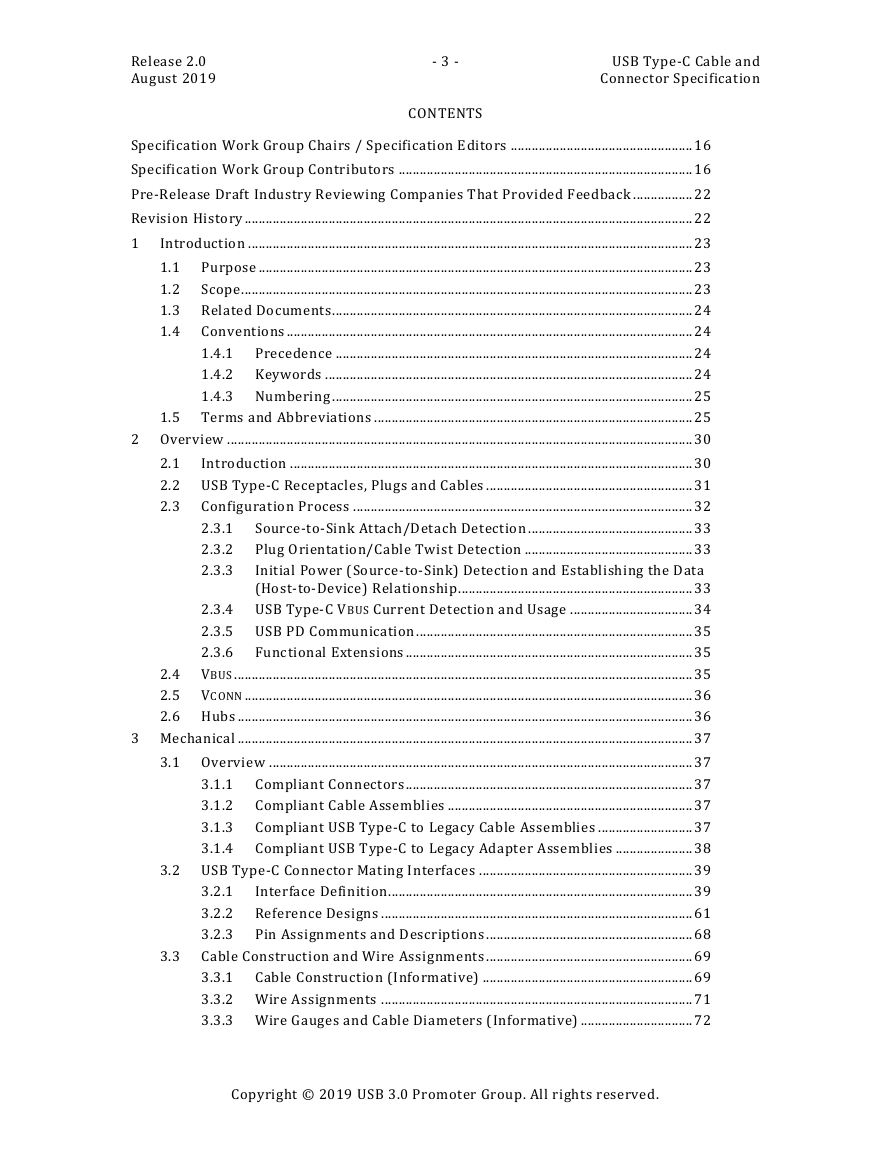
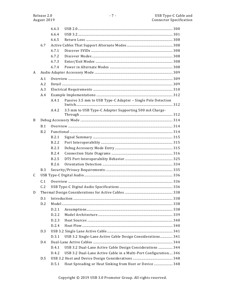
Release 2.0 August 2019 - 3 - CONTENTS USB Type-C Cable and Connector Specification Specification Work Group Chairs / Specification Editors .................................................... 16 Specification Work Group Contributors .................................................................................... 16 Pre-Release Draft Industry Reviewing Companies That Provided Feedback ................. 22 Revision History ................................................................................................................................ 22 1 Introduction ............................................................................................................................... 23 Purpose ............................................................................................................................ 23 1.1 1.2 Scope ................................................................................................................................. 23 1.3 Related Documents....................................................................................................... 24 1.4 Conventions .................................................................................................................... 24 1.4.1 Precedence ...................................................................................................... 24 1.4.2 Keywords ......................................................................................................... 24 1.4.3 Numbering ....................................................................................................... 25 1.5 Terms and Abbreviations ........................................................................................... 25 2 Overview ..................................................................................................................................... 30 2.1 Introduction ................................................................................................................... 30 2.2 USB Type-C Receptacles, Plugs and Cables ........................................................... 31 Configuration Process ................................................................................................. 32 2.3 Source-to-Sink Attach/Detach Detection ............................................... 33 2.3.1 2.3.2 Plug Orientation/Cable Twist Detection ................................................ 33 2.3.3 Initial Power (Source-to-Sink) Detection and Establishing the Data (Host-to-Device) Relationship ................................................................... 33 2.3.4 USB Type-C VBUS Current Detection and Usage ................................... 34 2.3.5 USB PD Communication ............................................................................... 35 Functional Extensions .................................................................................. 35 2.3.6 2.4 VBUS ................................................................................................................................... 35 2.5 VCONN ................................................................................................................................ 36 2.6 Hubs .................................................................................................................................. 36 3 Mechanical .................................................................................................................................. 37 3.1.1 3.1.2 3.1.3 3.1.4 3.1 Overview ......................................................................................................................... 37 Compliant Connectors .................................................................................. 37 Compliant Cable Assemblies ...................................................................... 37 Compliant USB Type-C to Legacy Cable Assemblies ........................... 37 Compliant USB Type-C to Legacy Adapter Assemblies ...................... 38 3.2 USB Type-C Connector Mating Interfaces ............................................................. 39 3.2.1 Interface Definition....................................................................................... 39 3.2.2 Reference Designs ......................................................................................... 61 3.2.3 Pin Assignments and Descriptions ........................................................... 68 Cable Construction and Wire Assignments ........................................................... 69 3.3.1 Cable Construction (Informative) ............................................................ 69 3.3.2 Wire Assignments ......................................................................................... 71 3.3.3 Wire Gauges and Cable Diameters (Informative) ................................ 72 3.3 Copyright © 2019 USB 3.0 Promoter Group. All rights reserved.
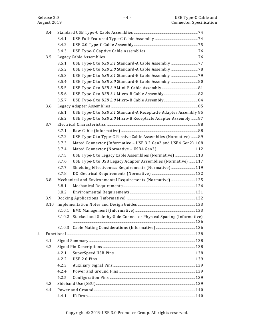
Release 2.0 August 2019 - 4 - USB Type-C Cable and Connector Specification 3.6 3.7 3.4 3.5 Standard USB Type-C Cable Assemblies ................................................................ 74 3.4.1 USB Full-Featured Type-C Cable Assembly ........................................... 74 3.4.2 USB 2.0 Type-C Cable Assembly ................................................................ 75 3.4.3 USB Type-C Captive Cable Assemblies .................................................... 76 Legacy Cable Assemblies ............................................................................................ 76 3.5.1 USB Type-C to USB 3.1 Standard-A Cable Assembly ........................... 77 3.5.2 USB Type-C to USB 2.0 Standard-A Cable Assembly ........................... 78 3.5.3 USB Type-C to USB 3.1 Standard-B Cable Assembly ........................... 79 3.5.4 USB Type-C to USB 2.0 Standard-B Cable Assembly ........................... 80 3.5.5 USB Type-C to USB 2.0 Mini-B Cable Assembly .................................... 81 3.5.6 USB Type-C to USB 3.1 Micro-B Cable Assembly .................................. 82 3.5.7 USB Type-C to USB 2.0 Micro-B Cable Assembly .................................. 84 Legacy Adapter Assemblies ....................................................................................... 85 3.6.1 USB Type-C to USB 3.1 Standard-A Receptacle Adapter Assembly 85 3.6.2 USB Type-C to USB 2.0 Micro-B Receptacle Adapter Assembly ....... 87 Electrical Characteristics ........................................................................................... 88 3.7.1 Raw Cable (Informative) ............................................................................. 88 3.7.2 USB Type-C to Type-C Passive Cable Assemblies (Normative) ....... 89 3.7.3 Mated Connector (Informative – USB 3.2 Gen2 and USB4 Gen2) 108 3.7.4 Mated Connector (Normative – USB4 Gen3) ...................................... 112 3.7.5 USB Type-C to Legacy Cable Assemblies (Normative) .................... 113 3.7.6 USB Type-C to USB Legacy Adapter Assemblies (Normative) ...... 117 3.7.7 Shielding Effectiveness Requirements (Normative) ........................ 119 3.7.8 DC Electrical Requirements (Normative) ........................................... 122 3.8 Mechanical and Environmental Requirements (Normative) ........................ 125 3.8.1 Mechanical Requirements ........................................................................ 126 3.8.2 Environmental Requirements................................................................. 131 3.9 Docking Applications (Informative) .................................................................... 132 3.10 Implementation Notes and Design Guides ......................................................... 133 3.10.1 EMC Management (Informative)............................................................ 133 3.10.2 Stacked and Side-by-Side Connector Physical Spacing (Informative) .......................................................................................................................... 136 3.10.3 Cable Mating Considerations (Informative) ....................................... 136 Functional ................................................................................................................................ 138 4.1 4.2 4.3 4.4 Signal Summary .......................................................................................................... 138 Signal Pin Descriptions ............................................................................................ 138 4.2.1 SuperSpeed USB Pins ................................................................................ 138 4.2.2 USB 2.0 Pins ................................................................................................. 139 4.2.3 Auxiliary Signal Pins .................................................................................. 139 Power and Ground Pins ............................................................................ 139 4.2.4 4.2.5 Configuration Pins ..................................................................................... 139 Sideband Use (SBU)................................................................................................... 139 Power and Ground ..................................................................................................... 140 4.4.1 IR Drop........................................................................................................... 140 Copyright © 2019 USB 3.0 Promoter Group. All rights reserved. 4
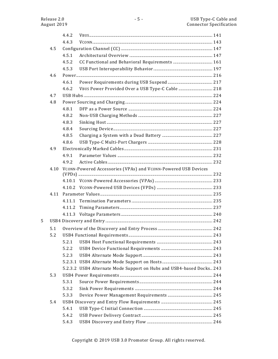
Release 2.0 August 2019 - 5 - USB Type-C Cable and Connector Specification 4.5 4.4.2 VBUS................................................................................................................. 141 4.4.3 VCONN .............................................................................................................. 143 Configuration Channel (CC) .................................................................................... 147 4.5.1 Architectural Overview ............................................................................ 147 4.5.2 CC Functional and Behavioral Requirements .................................... 161 4.5.3 USB Port Interoperability Behavior ...................................................... 197 Power............................................................................................................................. 216 4.6.1 Power Requirements during USB Suspend ......................................... 217 4.6.2 VBUS Power Provided Over a USB Type-C Cable ............................... 218 4.7 USB Hubs ...................................................................................................................... 224 4.8 Power Sourcing and Charging ................................................................................ 224 4.8.1 DFP as a Power Source ............................................................................. 224 4.8.2 Non-USB Charging Methods .................................................................... 227 Sinking Host ................................................................................................. 227 4.8.3 4.8.4 Sourcing Device ........................................................................................... 227 4.8.5 Charging a System with a Dead Battery .............................................. 227 4.8.6 USB Type-C Multi-Port Chargers ........................................................... 228 Electronically Marked Cables ................................................................................. 231 4.9.1 Parameter Values ....................................................................................... 232 4.9.2 Active Cables ................................................................................................ 232 4.6 4.9 4.10 VCONN-Powered Accessories (VPAs) and VCONN-Powered USB Devices (VPDs) ........................................................................................................................... 232 4.10.1 VCONN-Powered Accessories (VPAs) ..................................................... 233 4.10.2 VCONN-Powered USB Devices (VPDs) ................................................... 233 4.11 Parameter Values ....................................................................................................... 235 4.11.1 Termination Parameters .......................................................................... 235 4.11.2 Timing Parameters ..................................................................................... 237 4.11.3 Voltage Parameters .................................................................................... 240 5 USB4 Discovery and Entry .................................................................................................. 242 5.1 Overview of the Discovery and Entry Process .................................................. 242 5.2 USB4 Functional Requirements ............................................................................. 243 5.2.1 USB4 Host Functional Requirements ................................................... 243 5.2.2 USB4 Device Functional Requirements ............................................... 243 5.2.3 USB4 Alternate Mode Support ................................................................ 243 5.2.3.1 USB4 Alternate Mode Support on Hosts .............................................. 243 5.2.3.2 USB4 Alternate Mode Support on Hubs and USB4-based Docks .. 243 5.3 USB4 Power Requirements ..................................................................................... 244 Source Power Requirements ................................................................... 244 5.3.1 5.3.2 Sink Power Requirements ....................................................................... 244 5.3.3 Device Power Management Requirements ......................................... 245 5.4 USB4 Discovery and Entry Flow Requirements ............................................... 245 5.4.1 USB Type-C Initial Connection ............................................................... 245 5.4.2 USB Power Delivery Contract ................................................................. 245 5.4.3 USB4 Discovery and Entry Flow ............................................................ 246 Copyright © 2019 USB 3.0 Promoter Group. All rights reserved.
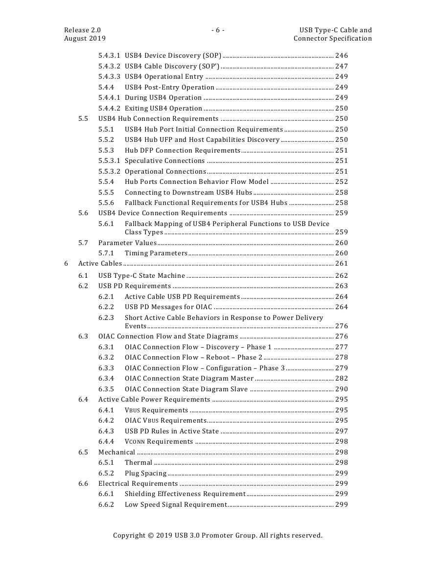
Release 2.0 August 2019 - 6 - USB Type-C Cable and Connector Specification 5.4.3.1 USB4 Device Discovery (SOP) ................................................................. 246 5.4.3.2 USB4 Cable Discovery (SOP’) .................................................................. 247 5.4.3.3 USB4 Operational Entry ........................................................................... 249 5.4.4 USB4 Post-Entry Operation ..................................................................... 249 5.4.4.1 During USB4 Operation ............................................................................ 249 5.4.4.2 Exiting USB4 Operation ............................................................................ 250 5.5 USB4 Hub Connection Requirements .................................................................. 250 5.5.1 USB4 Hub Port Initial Connection Requirements ............................. 250 5.5.2 USB4 Hub UFP and Host Capabilities Discovery ............................... 250 5.5.3 Hub DFP Connection Requirements ...................................................... 251 5.5.3.1 Speculative Connections .......................................................................... 251 5.5.3.2 Operational Connections .......................................................................... 251 5.5.4 Hub Ports Connection Behavior Flow Model ..................................... 252 Connecting to Downstream USB4 Hubs ............................................... 258 5.5.5 5.5.6 Fallback Functional Requirements for USB4 Hubs .......................... 258 5.6 USB4 Device Connection Requirements ............................................................. 259 5.6.1 Fallback Mapping of USB4 Peripheral Functions to USB Device Class Types ................................................................................................... 259 Parameter Values ....................................................................................................... 260 5.7.1 Timing Parameters ..................................................................................... 260 6 Active Cables ........................................................................................................................... 261 5.7 6.1 USB Type-C State Machine ...................................................................................... 262 6.2 USB PD Requirements .............................................................................................. 263 6.2.1 Active Cable USB PD Requirements ...................................................... 264 6.2.2 USB PD Messages for OIAC ...................................................................... 264 6.2.3 Short Active Cable Behaviors in Response to Power Delivery Events............................................................................................................. 276 6.3 OIAC Connection Flow and State Diagrams ....................................................... 276 6.3.1 OIAC Connection Flow – Discovery – Phase 1 ................................... 277 6.3.2 OIAC Connection Flow – Reboot – Phase 2 ......................................... 278 6.3.3 OIAC Connection Flow – Configuration – Phase 3 ............................ 279 6.3.4 OIAC Connection State Diagram Master .............................................. 282 6.3.5 OIAC Connection State Diagram Slave ................................................. 290 6.4 Active Cable Power Requirements ....................................................................... 295 6.4.1 VBUS Requirements .................................................................................... 295 6.4.2 OIAC VBUS Requirements .......................................................................... 295 6.4.3 USB PD Rules in Active State .................................................................. 297 6.4.4 VCONN Requirements ................................................................................. 298 6.5 Mechanical ................................................................................................................... 298 6.5.1 Thermal ......................................................................................................... 298 6.5.2 Plug Spacing ................................................................................................. 299 Electrical Requirements .......................................................................................... 299 Shielding Effectiveness Requirement ................................................... 299 6.6.1 6.6.2 Low Speed Signal Requirement .............................................................. 299 6.6 Copyright © 2019 USB 3.0 Promoter Group. All rights reserved.
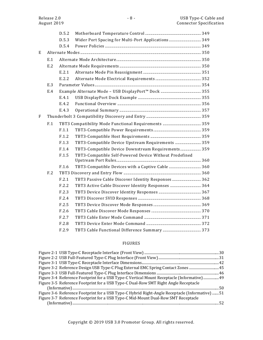
Release 2.0 August 2019 - 7 - USB Type-C Cable and Connector Specification 6.6.3 USB 2.0 ........................................................................................................... 300 6.6.4 USB 3.2 ........................................................................................................... 301 6.6.5 Return Loss .................................................................................................. 308 6.7 Active Cables That Support Alternate Modes .................................................... 308 6.7.1 Discover SVIDs ............................................................................................ 308 6.7.2 Discover Modes ........................................................................................... 308 Enter/Exit Modes ....................................................................................... 308 6.7.3 6.7.4 Power in Alternate Modes ....................................................................... 308 A Audio Adapter Accessory Mode ........................................................................................ 309 A.1 Overview ...................................................................................................................... 309 A.2 Detail ............................................................................................................................. 309 A.3 Electrical Requirements .......................................................................................... 310 A.4 Example Implementations ...................................................................................... 312 A.4.1 Passive 3.5 mm to USB Type-C Adapter – Single Pole Detection Switch ............................................................................................................. 312 A.4.2 3.5 mm to USB Type-C Adapter Supporting 500 mA Charge- Through ......................................................................................................... 312 B Debug Accessory Mode ........................................................................................................ 314 B.1 Overview ...................................................................................................................... 314 Functional .................................................................................................................... 314 B.2 B.2.1 Signal Summary .......................................................................................... 315 B.2.2 Port Interoperability ................................................................................. 315 B.2.3 Debug Accessory Mode Entry ................................................................. 315 B.2.4 Connection State Diagrams ..................................................................... 316 B.2.5 DTS Port Interoperability Behavior ...................................................... 325 B.2.6 Orientation Detection ............................................................................... 334 Security/Privacy Requirements: ........................................................................... 335 C USB Type-C Digital Audio .................................................................................................... 336 B.3 C.1 Overview ...................................................................................................................... 336 C.2 USB Type-C Digital Audio Specifications ............................................................ 336 D Thermal Design Considerations for Active Cables ...................................................... 338 D.1 Introduction ................................................................................................................ 338 D.2 Model ............................................................................................................................. 338 D.2.1 Assumptions ................................................................................................. 338 D.2.2 Model Architecture .................................................................................... 339 D.2.3 Heat Sources ................................................................................................ 340 D.2.4 Heat Flow ...................................................................................................... 340 D.3 USB 3.2 Single Lane Active Cable .......................................................................... 341 D.3.1 USB 3.2 Single-Lane Active Cable Design Considerations .............. 341 D.4 Dual-Lane Active Cables .......................................................................................... 344 D.4.1 USB 3.2 Dual-Lane Active Cable Design Considerations ................ 344 D.4.2 USB 3.2 Dual-Lane Active Cable in a Multi-Port Configuration .... 346 D.5 USB 3.2 Host and Device Design Considerations ............................................. 348 D.5.1 Heat Spreading or Heat Sinking from Host or Device ..................... 348 Copyright © 2019 USB 3.0 Promoter Group. All rights reserved.
Release 2.0 August 2019 - 8 - USB Type-C Cable and Connector Specification D.5.2 Motherboard Temperature Control ...................................................... 349 D.5.3 Wider Port Spacing for Multi-Port Applications ............................... 349 D.5.4 Power Policies ............................................................................................. 349 E Alternate Modes ..................................................................................................................... 350 E.1 Alternate Mode Architecture .................................................................................. 350 E.2 Alternate Mode Requirements ............................................................................... 350 E.2.1 Alternate Mode Pin Reassignment ........................................................ 351 E.2.2 Alternate Mode Electrical Requirements ............................................ 352 Parameter Values ....................................................................................................... 354 Example Alternate Mode – USB DisplayPort™ Dock ....................................... 355 E.4.1 USB DisplayPort Dock Example ............................................................. 355 E.4.2 Functional Overview ................................................................................. 356 E.4.3 Operational Summary ............................................................................... 357 F Thunderbolt 3 Compatibility Discovery and Entry ..................................................... 359 E.3 E.4 F.1 F.2 TBT3 Compatibility Mode Functional Requirements ..................................... 359 TBT3-Compatible Power Requirements .............................................. 359 F.1.1 TBT3-Compatible Host Requirements ................................................. 359 F.1.2 F.1.3 TBT3-Compatible Device Upstream Requirements ......................... 359 TBT3-Compatible Device Downstream Requirements .................... 359 F.1.4 F.1.5 TBT3-Compatible Self-Powered Device Without Predefined Upstream Port Rules.................................................................................. 360 F.1.6 TBT3-Compatible Devices with a Captive Cable ............................... 360 TBT3 Discovery and Entry Flow ........................................................................... 360 TBT3 Passive Cable Discover Identity Responses ............................ 362 F.2.1 F.2.2 TBT3 Active Cable Discover Identity Responses .............................. 364 TBT3 Device Discover Identity Responses ......................................... 367 F.2.3 TBT3 Discover SVID Responses ............................................................. 368 F.2.4 F.2.5 TBT3 Device Discover Mode Responses .............................................. 369 TBT3 Cable Discover Mode Responses ................................................ 370 F.2.6 TBT3 Cable Enter Mode Command ....................................................... 371 F.2.7 TBT3 Device Enter Mode Command ..................................................... 372 F.2.8 F.2.9 TBT3 Cable Functional Difference Summary ..................................... 373 FIGURES Figure 2-1 USB Type-C Receptacle Interface (Front View) ..................................................................................... 30 Figure 2-2 USB Full-Featured Type-C Plug Interface (Front View) ..................................................................... 31 Figure 3-1 USB Type-C Receptacle Interface Dimensions ........................................................................................ 42 Figure 3-2 Reference Design USB Type-C Plug External EMC Spring Contact Zones .................................. 45 Figure 3-3 USB Full-Featured Type-C Plug Interface Dimensions ....................................................................... 46 Figure 3-4 Reference Footprint for a USB Type-C Vertical Mount Receptacle (Informative) .................. 49 Figure 3-5 Reference Footprint for a USB Type-C Dual-Row SMT Right Angle Receptacle (Informative) ....................................................................................................................................................................... 50 Figure 3-6 Reference Footprint for a USB Type-C Hybrid Right-Angle Receptacle (Informative) ........ 51 Figure 3-7 Reference Footprint for a USB Type-C Mid-Mount Dual-Row SMT Receptacle (Informative) ....................................................................................................................................................................... 52 Copyright © 2019 USB 3.0 Promoter Group. All rights reserved.
分享到:
收藏