NVIDIA Jetson AGX Xavier Developer Kit
Carrier Board
Specification
SP-09778-001_v2.0 | January 2020
�
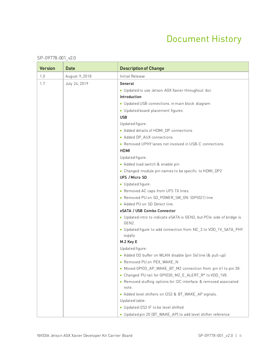
SP-09778-001_v2.0
Version
1.0
1.7
Date
August 9, 2018
July 24, 2019
Document History
Description of Change
Initial Release
General
• Updated to use Jetson AGX Xavier throughout doc
Introduction
• Updated USB connections in main block diagram
• Updated board placement figures
USB
Updated figure:
• Added details of HDMI_DP connections
• Added DP_AUX connections
• Removed UPHY lanes not involved in USB-C connections
HDMI
Updated figure:
• Added load switch & enable pin
• Changed module pin names to be specific to HDMI_DP2
UFS / Micro SD
• Updated figure:
• Removed AC caps from UFS TX lines.
• Removed PU on SD_POWER_SW_ON (GPIO21) line
• Added PU on SD Detect line.
eSATA / USB Combo Connector
• Updated intro to indicate eSATA is GEN3, but PCIe side of bridge is
GEN2.
• Updated figure to add connection from NC_3 to VDD_1V_SATA_PHY
supply
M.2 Key E
Updated figure:
• Added OD buffer on WLAN disable (pin 56) line (& pull-up)
• Removed PU on PEX_WAKE_N
• Moved GPIO3_AP_WAKE_BT_M2 connection from pin 61 to pin 38.
• Changed PU rail for GPIO30_M2_E_ALERT_R* to VDD_1V8.
• Removed stuffing options for I2C interface & removed associated
note.
• Added level shifters on I2S3 & BT_WAKE_AP signals.
Updated table:
• Updated I2S3 IF to be level shifted
• Updated pin 20 (BT_WAKE_AP) to add level shifter reference
NVIDIA Jetson AGX Xavier Developer Kit Carrier Board
SP-09778-001_v2.0 | ii
�
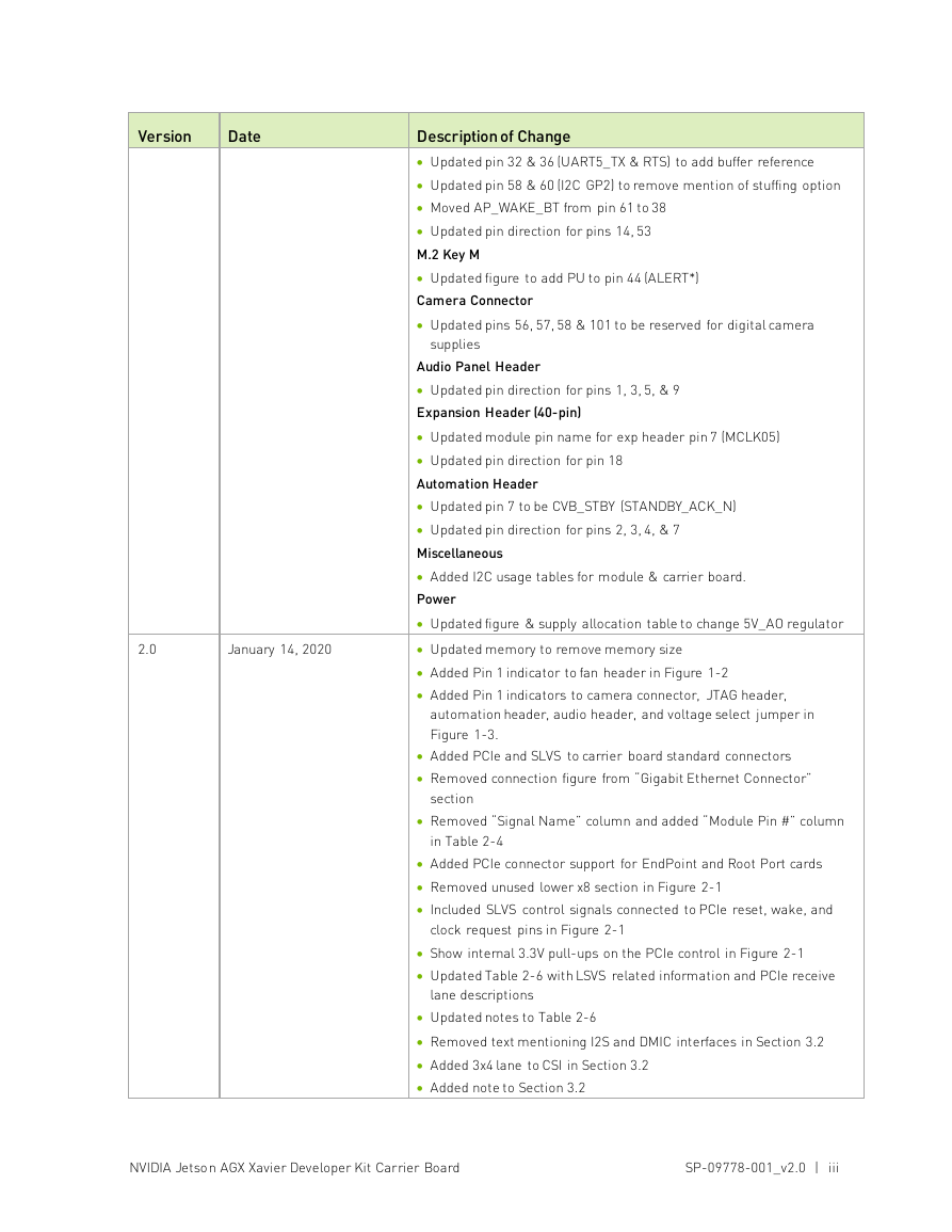
Version
Date
2.0
January 14, 2020
Description of Change
• Updated pin 32 & 36 (UART5_TX & RTS) to add buffer reference
• Updated pin 58 & 60 (I2C GP2) to remove mention of stuffing option
• Moved AP_WAKE_BT from pin 61 to 38
• Updated pin direction for pins 14, 53
M.2 Key M
• Updated figure to add PU to pin 44 (ALERT*)
Camera Connector
• Updated pins 56, 57, 58 & 101 to be reserved for digital camera
supplies
Audio Panel Header
• Updated pin direction for pins 1, 3, 5, & 9
Expansion Header (40-pin)
• Updated module pin name for exp header pin 7 (MCLK05)
• Updated pin direction for pin 18
Automation Header
• Updated pin 7 to be CVB_STBY (STANDBY_ACK_N)
• Updated pin direction for pins 2, 3, 4, & 7
Miscellaneous
• Added I2C usage tables for module & carrier board.
Power
• Updated figure & supply allocation table to change 5V_AO regulator
• Updated memory to remove memory size
• Added Pin 1 indicator to fan header in Figure 1-2
• Added Pin 1 indicators to camera connector, JTAG header,
automation header, audio header, and voltage select jumper in
Figure 1-3.
• Added PCIe and SLVS to carrier board standard connectors
• Removed connection figure from “Gigabit Ethernet Connector”
section
• Removed “Signal Name” column and added “Module Pin #” column
in Table 2-4
• Added PCIe connector support for EndPoint and Root Port cards
• Removed unused lower x8 section in Figure 2-1
• Included SLVS control signals connected to PCIe reset, wake, and
clock request pins in Figure 2-1
• Show internal 3.3V pull-ups on the PCIe control in Figure 2-1
• Updated Table 2-6 with LSVS related information and PCIe receive
lane descriptions
• Updated notes to Table 2-6
• Removed text mentioning I2S and DMIC interfaces in Section 3.2
• Added 3x4 lane to CSI in Section 3.2
• Added note to Section 3.2
NVIDIA Jetson AGX Xavier Developer Kit Carrier Board
SP-09778-001_v2.0 | iii
�
Description of Change
• Removed C-PHY connection example from Figure 3-1
• Removed note related to SPI in Table 3-2
• Updated connector on the carrier board to Wieson G2100CE04C-008-
H
• Updated VBUS[2:1] power rail usage in Table 5-1
• Added Table 5-3 based on P2822 power tree
Version
Date
NVIDIA Jetson AGX Xavier Developer Kit Carrier Board
SP-09778-001_v2.0 | iv
�
Table of Contents
Chapter 1.
Introduction ................................................................................................ 1
1.1
Jetson AGX Xavier Feature List .................................................................................2
1.2 Carrier Board Feature List .......................................................................................2
1.3
Jetson AGX Xavier Carrier Board Block Diagram .......................................................3
Jetson Carrier Board Standard Connectors ........................................... 7
2.1 USB Ports ...............................................................................................................8
2.2 Gigabit Ethernet Connector ......................................................................................9
2.3 HDMI Connector .................................................................................................... 10
2.4 PCIe x16 Connector ............................................................................................... 10
2.5 UFS and Micro SD Card Socket .............................................................................. 13
2.6 eSATA and USB 3.1 Type A Connector..................................................................... 14
2.7 M.2 Key E Expansion Slot ....................................................................................... 14
2.8 M.2 Key M Expansion Slot ...................................................................................... 16
2.9 Audio Panel Header ............................................................................................... 18
2.10 JTAG Header ......................................................................................................... 19
Chapter 3. Carrier Board Custom Expansion Connections .................................... 20
3.1 Module Connector ................................................................................................. 20
3.2 Camera Expansion Header ..................................................................................... 20
3.3
40-Pin Expansion Header ....................................................................................... 23
3.3.1 40-Pin Expansion Header Interface Guidelines .................................................. 25
3.4 Fan Control ........................................................................................................... 25
3.5 Automation Header ................................................................................................ 26
3.6 DC Power Jack ...................................................................................................... 27
Chapter 4. Miscellaneous .......................................................................................... 28
4.1 Buttons, Jumpers and Indicators............................................................................ 28
I2C Interface Usage ............................................................................................... 29
4.2
Interface Power ........................................................................................ 30
Chapter 2.
Chapter 5.
NVIDIA Jetson AGX Xavier Developer Kit Carrier Board
SP-09778-001_v2.0 | v
�
List of Figures
Figure 1-1.
Jetson AGX Xavier Carrier Board Block Diagram ............................................4
Figure 1-2.
Jetson AGX Xavier Carrier Board Placement – Module Connector Side ...........5
Figure 1-3.
Jetson AGX Xavier Carrier Board Placement – Non-module Connector Side ...6
Figure 2-1.
PCIe x16 Connector Connections ................................................................. 11
Figure 2-2. M.2 Key E Connections................................................................................ 15
Audio Panel Header Connections................................................................. 18
Figure 2-3.
Figure 3-1.
Camera CSI Connections – D-PHY ............................................................... 22
Expansion Header Top View......................................................................... 23
Figure 3-2.
4-Pin Fan Header – J9 ................................................................................ 25
Figure 3-3.
Figure 5-1.
Interface Connector Power Diagram............................................................ 30
NVIDIA Jetson AGX Xavier Developer Kit Carrier Board
SP-09778-001_v2.0 | vi
�
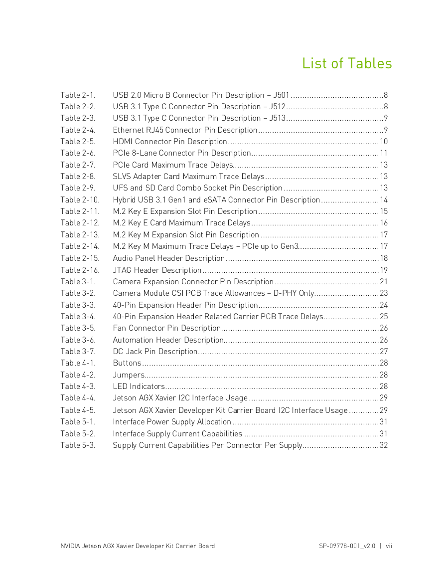
List of Tables
USB 2.0 Micro B Connector Pin Description – J501 ........................................8
Table 2-1.
USB 3.1 Type C Connector Pin Description – J512 ..........................................8
Table 2-2.
USB 3.1 Type C Connector Pin Description – J513 ..........................................9
Table 2-3.
Ethernet RJ45 Connector Pin Description ......................................................9
Table 2-4.
HDMI Connector Pin Description ................................................................. 10
Table 2-5.
PCIe 8-Lane Connector Pin Description ....................................................... 11
Table 2-6.
PCIe Card Maximum Trace Delays............................................................... 13
Table 2-7.
SLVS Adapter Card Maximum Trace Delays ................................................. 13
Table 2-8.
Table 2-9.
UFS and SD Card Combo Socket Pin Description ......................................... 13
Table 2-10. Hybrid USB 3.1 Gen1 and eSATA Connector Pin Description ......................... 14
Table 2-11. M.2 Key E Expansion Slot Pin Description .................................................... 15
Table 2-12. M.2 Key E Card Maximum Trace Delays ....................................................... 16
Table 2-13. M.2 Key M Expansion Slot Pin Description ................................................... 17
Table 2-14. M.2 Key M Maximum Trace Delays – PCIe up to Gen3................................... 17
Audio Panel Header Description .................................................................. 18
Table 2-15.
Table 2-16.
JTAG Header Description ............................................................................ 19
Camera Expansion Connector Pin Description ............................................. 21
Table 3-1.
Camera Module CSI PCB Trace Allowances – D-PHY Only ............................ 23
Table 3-2.
Table 3-3.
40-Pin Expansion Header Pin Description .................................................... 24
40-Pin Expansion Header Related Carrier PCB Trace Delays........................ 25
Table 3-4.
Fan Connector Pin Description .................................................................... 26
Table 3-5.
Automation Header Description................................................................... 26
Table 3-6.
Table 3-7.
DC Jack Pin Description.............................................................................. 27
Buttons ...................................................................................................... 28
Table 4-1.
Jumpers..................................................................................................... 28
Table 4-2.
Table 4-3.
LED Indicators ............................................................................................ 28
Jetson AGX Xavier I2C Interface Usage ........................................................ 29
Table 4-4.
Jetson AGX Xavier Developer Kit Carrier Board I2C Interface Usage ............. 29
Table 4-5.
Table 5-1.
Interface Power Supply Allocation ............................................................... 31
Interface Supply Current Capabilities .......................................................... 31
Table 5-2.
Table 5-3.
Supply Current Capabilities Per Connector Per Supply ................................. 32
NVIDIA Jetson AGX Xavier Developer Kit Carrier Board
SP-09778-001_v2.0 | vii
�
Chapter 1. Introduction
This specification contains recommendations and guidelines for engineers to follow to create
modules for the expansion connectors on the NVIDIA® Jetson AGX Xavier™ carrier board as
well as understand the capabilities of the other dedicated interface connectors and associated
power solutions on the platform.
! CAUTION: ALWAYS CONNECT THE JETSON AGX XAVIER AND ALL EXTERNAL PERIPHERAL
DEVICES BEFORE CONNECTING THE POWER SUPPLY TO THE AC POWER JACK OR TYPE C
CONNECTOR.
The Jetson AGX Xavier Developer Kit carrier board contains ESD-sensitive parts. Always use
appropriate anti-static and grounding techniques when working with the system. Failure to do so
can result in ESD discharge to sensitive pins, and irreparably damage your Jetson AGX Xavier
carrier board. NVIDIA will not replace units that have been damaged due to ESD discharge.
The Jetson AGX Xavier carrier board is ideal for software development within the Linux
environment. Standard connectors are used to access Jetson AGX Xavier features and
interfaces, enabling a highly flexible and extensible development platform. Go to
https://developer.nvidia.com/embedded-computing or contact your NVIDIA representative for
access to software updates and the developer SDK supporting the OS image and host
development platform that you want to use. The developer SDK includes an OS image that you
will load onto your Jetson AGX Xavier device, supporting documentation, and code samples to
help you get started.
NVIDIA Jetson AGX Xavier Developer Kit Carrier Board
SP-09778-001_v2.0 | 1
�




 2023年江西萍乡中考道德与法治真题及答案.doc
 2012年重庆南川中考生物真题及答案.doc
 2013年江西师范大学地理学综合及文艺理论基础考研真题.doc
 2020年四川甘孜小升初语文真题及答案I卷.doc
 2020年注册岩土工程师专业基础考试真题及答案.doc
 2023-2024学年福建省厦门市九年级上学期数学月考试题及答案.doc
 2021-2022学年辽宁省沈阳市大东区九年级上学期语文期末试题及答案.doc
 2022-2023学年北京东城区初三第一学期物理期末试卷及答案.doc
 2018上半年江西教师资格初中地理学科知识与教学能力真题及答案.doc
 2012年河北国家公务员申论考试真题及答案-省级.doc
 2020-2021学年江苏省扬州市江都区邵樊片九年级上学期数学第一次质量检测试题及答案.doc
 2022下半年黑龙江教师资格证中学综合素质真题及答案.doc