GV7600 Aviia™ Transmitter Data Sheet
Key Features
•
Serial digital video transmitter for standard and high
definition component video:
SD 525i and 625i
HD 720p 24, 25, 30, 50 and 60
HD 1080i 50, 60
HD 1080p 24, 25, 30, 50 and 60
Supports 8-bit, 10-bit or 12-bit component digital
video:
RGB or YCbCr 4:4:4 sampled
YCbCr 4:2:2 or 4:2:0 sampled
Single 75Ω coaxial cable driver output
Integrated audio embedder for the carriage of up to 8
channels of 48kHz digital audio
•
•
•
• Asynchronous Serial Interface (ASI) for transmission of
IEC 13818-1 compliant transport streams
• Ancillary (ANC) data insertion
• User selectable processing features, including:
Timing Reference Signal (TRS) insertion
Programmable ANC data insertion
Illegal video code word re-mapping
4-wire Gennum Serial Peripheral Interface (GSPI) for
external host command and control
•
• Dedicated JTAG test interface
•
•
•
•
•
1.2V core and 3.3V analog voltage power supplies
1.8V or 3.3V selectable digital I/O power supply
Small footprint 100-BGA (11mm x 11mm)
Low power operation, typically 400mW
Pb-free and RoHS compliant
Industrial & professional cameras
Applications
•
• Digital video recorders (DVR)
• Video servers
• Video mixers and switchers
• Camcorders
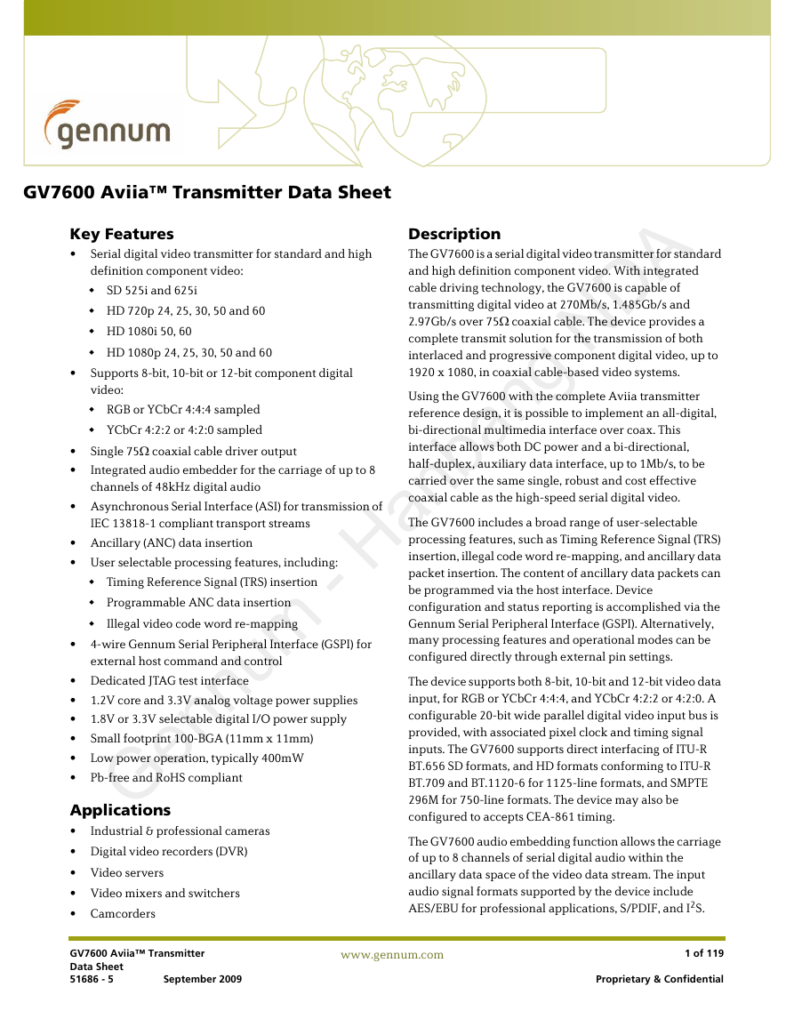
Description
The GV7600 is a serial digital video transmitter for standard
and high definition component video. With integrated
cable driving technology, the GV7600 is capable of
transmitting digital video at 270Mb/s, 1.485Gb/s and
2.97Gb/s over 75Ω coaxial cable. The device provides a
complete transmit solution for the transmission of both
interlaced and progressive component digital video, up to
1920 x 1080, in coaxial cable-based video systems.
Using the GV7600 with the complete Aviia transmitter
reference design, it is possible to implement an all-digital,
bi-directional multimedia interface over coax. This
interface allows both DC power and a bi-directional,
half-duplex, auxiliary data interface, up to 1Mb/s, to be
carried over the same single, robust and cost effective
coaxial cable as the high-speed serial digital video.
The GV7600 includes a broad range of user-selectable
processing features, such as Timing Reference Signal (TRS)
insertion, illegal code word re-mapping, and ancillary data
packet insertion. The content of ancillary data packets can
be programmed via the host interface. Device
configuration and status reporting is accomplished via the
Gennum Serial Peripheral Interface (GSPI). Alternatively,
many processing features and operational modes can be
configured directly through external pin settings.
The device supports both 8-bit, 10-bit and 12-bit video data
input, for RGB or YCbCr 4:4:4, and YCbCr 4:2:2 or 4:2:0. A
configurable 20-bit wide parallel digital video input bus is
provided, with associated pixel clock and timing signal
inputs. The GV7600 supports direct interfacing of ITU-R
BT.656 SD formats, and HD formats conforming to ITU-R
BT.709 and BT.1120-6 for 1125-line formats, and SMPTE
296M for 750-line formats. The device may also be
configured to accepts CEA-861 timing.
The GV7600 audio embedding function allows the carriage
of up to 8 channels of serial digital audio within the
ancillary data space of the video data stream. The input
audio signal formats supported by the device include
AES/EBU for professional applications, S/PDIF, and I2S.
GV7600 Aviia™ Transmitter
Data Sheet
51686 - 5
September 2009
www.gennum.com
1 of 119
Proprietary & Confidential
�
16-bit, 20-bit and 24-bit audio formats are supported at
48kHz synchronous-to-video for SD video formats and
48kHz synchronous or asynchronous for HD formats.
Additional audio processing features include: individual
channel enabling, audio group selection, group
replacement, channel swapping and audio channel status
insertion.
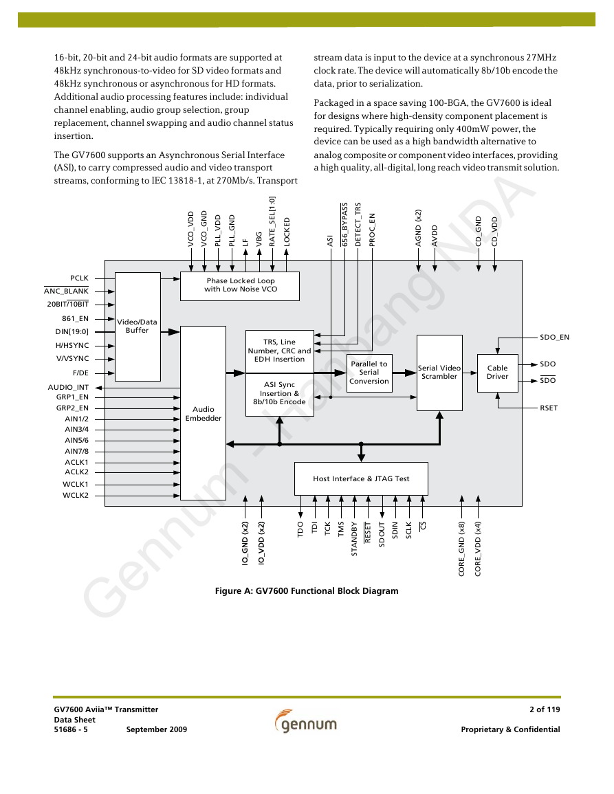
The GV7600 supports an Asynchronous Serial Interface
(ASI), to carry compressed audio and video transport
streams, conforming to IEC 13818-1, at 270Mb/s. Transport
stream data is input to the device at a synchronous 27MHz
clock rate. The device will automatically 8b/10b encode the
data, prior to serialization.
Packaged in a space saving 100-BGA, the GV7600 is ideal
for designs where high-density component placement is
required. Typically requiring only 400mW power, the
device can be used as a high bandwidth alternative to
analog composite or component video interfaces, providing
a high quality, all-digital, long reach video transmit solution.
D
D
V
_
O
C
V
D
N
G
_
O
C
V
D
D
V
_
L
L
P
D
N
G
_
L
L
P
G
B
V
F
L
]
0
:
1
[
L
E
S
_
E
T
A
R
D
E
K
C
O
L
S
S
A
P
Y
B
_
6
5
6
S
R
T
_
T
C
E
T
E
D
N
E
_
C
O
R
P
I
S
A
)
2
x
(
D
N
G
A
D
D
V
A
D
N
G
_
D
C
D
D
V
_
D
C
PCLK
ANC_BLANK
20BIT/10BIT
861_EN
DIN[19:0]
H/HSYNC
V/VSYNC
F/DE
AUDIO_INT
GRP1_EN
GRP2_EN
AIN1/2
AIN3/4
AIN5/6
AIN7/8
ACLK1
ACLK2
WCLK1
WCLK2
Video/Data
Buffer
Phase Locked Loop
with Low Noise VCO
TRS, Line
Number, CRC and
EDH Insertion
ASI Sync
Insertion &
8b/10b Encode
Audio
Embedder
Parallel to
Serial
Conversion
Serial Video
Scrambler
Cable
Driver
SDO_EN
SDO
SDO
RSET
Host Interface & JTAG Test
O
D
T
I
D
T
K
C
T
S
M
T
I
N
D
S
K
L
C
S
S
C
T
E
S
E
R
T
U
O
D
S
Y
B
D
N
A
T
S
)
8
x
(
D
N
G
_
E
R
O
C
)
4
x
(
D
D
V
_
E
R
O
C
)
)
2
2
x
x
(
(
D
D
N
N
G
G
_
_
O
O
I
I
)
)
2
2
x
x
(
(
D
D
D
D
V
V
_
_
O
O
I
I
Figure A: GV7600 Functional Block Diagram
GV7600 Aviia™ Transmitter
Data Sheet
51686 - 5
September 2009
2 of 119
Proprietary & Confidential
�
Revision History
Version
ECR
Date
Changes and / or Modifications
5
4
3
2
1
152573
September 2009
Changed Reset Pulse Width from 10ms to 1ms.
152157
June 2009
Changed Figure 4-54 and 6.3 Marking
Diagram.
151832
May 2009
151644
April 2009
151321
February 2009
Re-ordered the DIN[19:10] & DIN[9:0] in
Table 1-1 to reflect the pin names.
Added Device Latency in Table 2-4.
Changed description in Section 4.7.2.
Changed Figure 4-47.
Changed descriptions to address 40Bh in
Table 4-31 & address 80Ah in Table 4-32.
Changed 4.8.1 Ancillary Data Insertion
Operating Modes and their registers.
Altered Parallel Video Data Inputs DIN[9:0] &
DIN[9:0] section.
Changed table in Full HD Input Formats
section.
Added Aviia 20-bit Mapping Structure for
1280x720 100/120Hz Progressive 4:2:2
(Y’C’BC’R) 8/10-bit Signals.
Added section: Video Format & Bandwidth
Requirements.
Changed/Added to H:V:F Timing diagrams.
Added GSPI timing delay values.
Added Index.
0
150962
December 2008
New document.
Contents
Key Features........................................................................................................................................................1
Applications.........................................................................................................................................................1
Description...........................................................................................................................................................1
1. Pin Out...............................................................................................................................................................9
1.1 Pin Assignment ..................................................................................................................................9
1.2 Pin Descriptions ............................................................................................................................. 10
2. Electrical Characteristics ......................................................................................................................... 17
2.1 Absolute Maximum Ratings ....................................................................................................... 17
2.2 Recommended Operating Conditions .................................................................................... 17
2.3 DC Electrical Characteristics ..................................................................................................... 18
2.4 AC Electrical Characteristics ..................................................................................................... 20
3. Input/Output Circuits ............................................................................................................................... 23
GV7600 Aviia™ Transmitter
Data Sheet
51686 - 5
September 2009
3 of 119
Proprietary & Confidential
�
4. Detailed Description.................................................................................................................................. 28
4.1 Functional Overview .................................................................................................................... 28
4.2 Parallel Video Data Inputs DIN[9:0] & DIN[19:10] .............................................................. 29
4.2.1 Parallel Input In Video Mode......................................................................................... 31
4.2.2 Parallel Input in ASI Mode.............................................................................................. 49
4.2.3 Parallel Input in Data-Through Mode......................................................................... 50
4.2.4 Parallel Input Clock (PCLK) ............................................................................................ 50
4.3 Video Mode ..................................................................................................................................... 51
4.3.1 H:V:F Timing ....................................................................................................................... 51
4.3.2 CEA-861 Timing................................................................................................................. 53
4.4 ASI Mode .......................................................................................................................................... 64
4.5 Data-Through Mode ..................................................................................................................... 65
4.6 Standby Mode ................................................................................................................................. 65
4.7 Audio Embedding .......................................................................................................................... 65
4.7.1 Serial Audio Data Inputs ................................................................................................. 65
4.7.2 Serial Audio Data Format Support............................................................................... 67
4.7.3 Audio Embedding Operating Modes .......................................................................... 68
4.7.4 Audio Packet Detection................................................................................................... 69
4.7.5 Audio Packet Detection and Deletion - SD Detail .................................................. 69
4.7.6 Audio Mute (Default Off) ................................................................................................ 70
4.7.7 Audio Channel Status....................................................................................................... 70
4.7.8 Audio Crosspoint ............................................................................................................... 71
4.7.9 Audio Word Clock............................................................................................................. 72
4.7.10 Channel & Group Activation ....................................................................................... 72
4.7.11 ECC Error Detection and Correction ........................................................................ 72
4.7.12 Audio Control Packet Insertion - SD......................................................................... 73
4.7.13 Audio Control Packet Insertion - HD........................................................................ 74
4.7.14 Audio Interrupt Control................................................................................................ 75
4.8 Ancillary Data Insertion .............................................................................................................. 75
4.8.1 Ancillary Data Insertion Operating Modes............................................................... 77
4.9 Additional Processing Functions .............................................................................................. 78
4.9.1 Video Format Detection .................................................................................................. 78
4.9.2 Ancillary Data Blanking.................................................................................................. 80
4.9.3 Ancillary Data Checksum Calculation and Insertion............................................ 80
4.9.4 TRS Generation and Insertion ....................................................................................... 80
4.9.5 HD Line Number Calculation and Insertion............................................................. 81
4.9.6 Illegal Code Re-Mapping................................................................................................. 81
4.9.7 Line Based CRC Generation and Insertion................................................................ 81
4.9.8 EDH Generation and Insertion...................................................................................... 81
4.9.9 Video Processing................................................................................................................ 83
4.9.10 Processing Feature Disable.......................................................................................... 83
4.10 Parallel to Serial Conversion ................................................................................................... 84
4.11 Serial Clock PLL ........................................................................................................................... 84
4.11.1 PLL Bandwidth................................................................................................................. 84
4.12 Lock Detect .................................................................................................................................... 85
GV7600 Aviia™ Transmitter
Data Sheet
51686 - 5
September 2009
4 of 119
Proprietary & Confidential
�
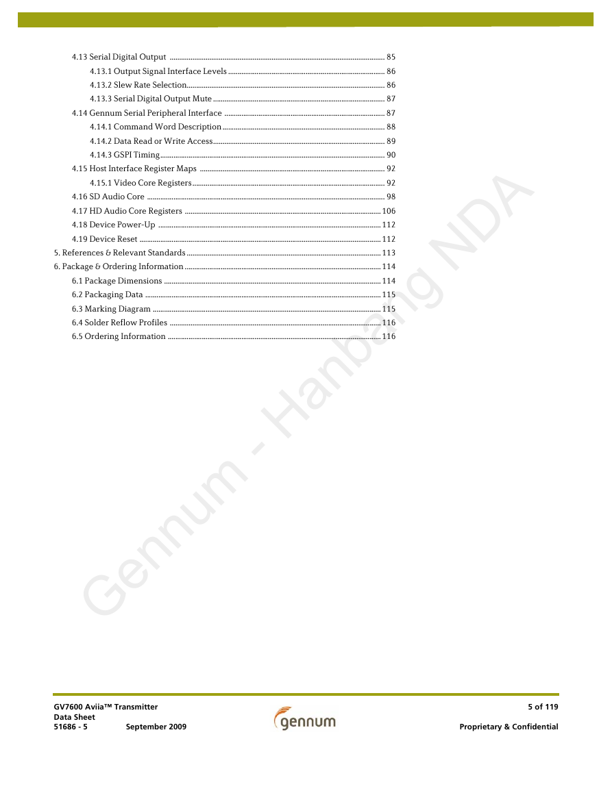
4.13 Serial Digital Output .................................................................................................................. 85
4.13.1 Output Signal Interface Levels ................................................................................... 86
4.13.2 Slew Rate Selection......................................................................................................... 86
4.13.3 Serial Digital Output Mute ........................................................................................... 87
4.14 Gennum Serial Peripheral Interface ..................................................................................... 87
4.14.1 Command Word Description ...................................................................................... 88
4.14.2 Data Read or Write Access........................................................................................... 89
4.14.3 GSPI Timing....................................................................................................................... 90
4.15 Host Interface Register Maps .................................................................................................. 92
4.15.1 Video Core Registers...................................................................................................... 92
4.16 SD Audio Core .............................................................................................................................. 98
4.17 HD Audio Core Registers ........................................................................................................106
4.18 Device Power-Up ......................................................................................................................112
4.19 Device Reset ................................................................................................................................112
5. References & Relevant Standards .......................................................................................................113
6. Package & Ordering Information ........................................................................................................114
6.1 Package Dimensions ...................................................................................................................114
6.2 Packaging Data .............................................................................................................................115
6.3 Marking Diagram .........................................................................................................................115
6.4 Solder Reflow Profiles ................................................................................................................116
6.5 Ordering Information .................................................................................................................116
GV7600 Aviia™ Transmitter
Data Sheet
51686 - 5
September 2009
5 of 119
Proprietary & Confidential
�
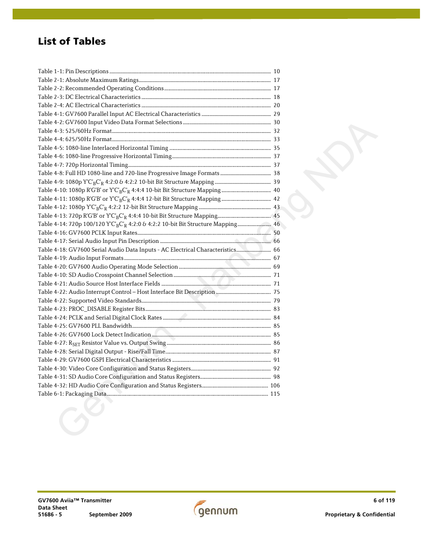
List of Tables
Table 1-1: Pin Descriptions ......................................................................................................................... 10
Table 2-1: Absolute Maximum Ratings................................................................................................... 17
Table 2-2: Recommended Operating Conditions................................................................................ 17
Table 2-3: DC Electrical Characteristics ................................................................................................. 18
Table 2-4: AC Electrical Characteristics ................................................................................................. 20
Table 4-1: GV7600 Parallel Input AC Electrical Characteristics .................................................... 29
Table 4-2: GV7600 Input Video Data Format Selections .................................................................. 30
Table 4-3: 525/60Hz Format....................................................................................................................... 32
Table 4-4: 625/50Hz Format....................................................................................................................... 33
Table 4-5: 1080-line Interlaced Horizontal Timing ............................................................................ 35
Table 4-6: 1080-line Progressive Horizontal Timing.......................................................................... 37
Table 4-7: 720p Horizontal Timing........................................................................................................... 37
Table 4-8: Full HD 1080-line and 720-line Progressive Image Formats ...................................... 38
Table 4-9: 1080p Y'C'BC'R 4:2:0 & 4:2:2 10-bit Bit Structure Mapping .......................................... 39
Table 4-10: 1080p R'G'B' or Y'C'BC'R 4:4:4 10-bit Bit Structure Mapping ..................................... 40
Table 4-11: 1080p R'G'B' or Y'C'BC'R 4:4:4 12-bit Bit Structure Mapping ..................................... 42
Table 4-12: 1080p Y'C'BC'R 4:2:2 12-bit Bit Structure Mapping ...................................................... 43
Table 4-13: 720p R'G'B' or Y'C'BC'R 4:4:4 10-bit Bit Structure Mapping........................................ 45
Table 4-14: 720p 100/120 Y'C'BC'R 4:2:0 & 4:2:2 10-bit Bit Structure Mapping......................... 46
Table 4-16: GV7600 PCLK Input Rates.................................................................................................... 50
Table 4-17: Serial Audio Input Pin Description ................................................................................... 66
Table 4-18: GV7600 Serial Audio Data Inputs - AC Electrical Characteristics.......................... 66
Table 4-19: Audio Input Formats.............................................................................................................. 67
Table 4-20: GV7600 Audio Operating Mode Selection ..................................................................... 69
Table 4-10: SD Audio Crosspoint Channel Selection ......................................................................... 71
Table 4-21: Audio Source Host Interface Fields .................................................................................. 71
Table 4-22: Audio Interrupt Control – Host Interface Bit Description ......................................... 75
Table 4-22: Supported Video Standards................................................................................................. 79
Table 4-23: PROC_DISABLE Register Bits.............................................................................................. 83
Table 4-24: PCLK and Serial Digital Clock Rates ................................................................................. 84
Table 4-25: GV7600 PLL Bandwidth........................................................................................................ 85
Table 4-26: GV7600 Lock Detect Indication ......................................................................................... 85
Table 4-27: RSET Resistor Value vs. Output Swing .............................................................................. 86
Table 4-28: Serial Digital Output - Rise/Fall Time............................................................................... 87
Table 4-29: GV7600 GSPI Electrical Characteristics .......................................................................... 91
Table 4-30: Video Core Configuration and Status Registers............................................................ 92
Table 4-31: SD Audio Core Configuration and Status Registers..................................................... 98
Table 4-32: HD Audio Core Configuration and Status Registers.................................................. 106
Table 6-1: Packaging Data......................................................................................................................... 115
GV7600 Aviia™ Transmitter
Data Sheet
51686 - 5
September 2009
6 of 119
Proprietary & Confidential
�
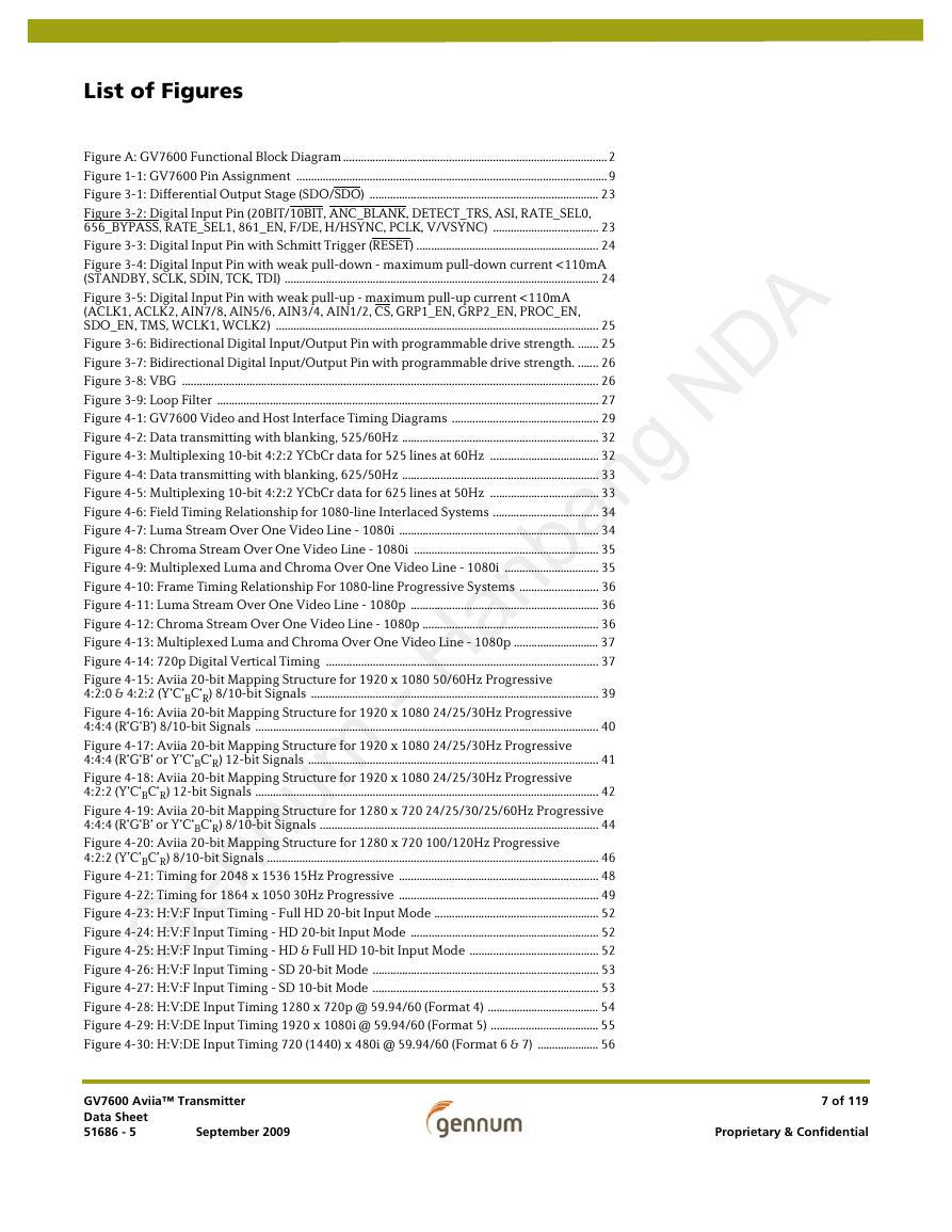
List of Figures
Figure A: GV7600 Functional Block Diagram ..........................................................................................2
Figure 1-1: GV7600 Pin Assignment ..........................................................................................................9
Figure 3-1: Differential Output Stage (SDO/SDO) .............................................................................. 23
Figure 3-2: Digital Input Pin (20BIT/10BIT, ANC_BLANK, DETECT_TRS, ASI, RATE_SEL0,
656_BYPASS, RATE_SEL1, 861_EN, F/DE, H/HSYNC, PCLK, V/VSYNC) .................................... 23
Figure 3-3: Digital Input Pin with Schmitt Trigger (RESET) .............................................................. 24
Figure 3-4: Digital Input Pin with weak pull-down - maximum pull-down current <110mA
(STANDBY, SCLK, SDIN, TCK, TDI) ........................................................................................................... 24
Figure 3-5: Digital Input Pin with weak pull-up - maximum pull-up current <110mA
(ACLK1, ACLK2, AIN7/8, AIN5/6, AIN3/4, AIN1/2, CS, GRP1_EN, GRP2_EN, PROC_EN,
SDO_EN, TMS, WCLK1, WCLK2) .............................................................................................................. 25
Figure 3-6: Bidirectional Digital Input/Output Pin with programmable drive strength. ....... 25
Figure 3-7: Bidirectional Digital Input/Output Pin with programmable drive strength. ....... 26
Figure 3-8: VBG .............................................................................................................................................. 26
Figure 3-9: Loop Filter .................................................................................................................................. 27
Figure 4-1: GV7600 Video and Host Interface Timing Diagrams .................................................. 29
Figure 4-2: Data transmitting with blanking, 525/60Hz ................................................................... 32
Figure 4-3: Multiplexing 10-bit 4:2:2 YCbCr data for 525 lines at 60Hz ..................................... 32
Figure 4-4: Data transmitting with blanking, 625/50Hz ................................................................... 33
Figure 4-5: Multiplexing 10-bit 4:2:2 YCbCr data for 625 lines at 50Hz ..................................... 33
Figure 4-6: Field Timing Relationship for 1080-line Interlaced Systems .................................... 34
Figure 4-7: Luma Stream Over One Video Line - 1080i .................................................................... 34
Figure 4-8: Chroma Stream Over One Video Line - 1080i ............................................................... 35
Figure 4-9: Multiplexed Luma and Chroma Over One Video Line - 1080i ................................ 35
Figure 4-10: Frame Timing Relationship For 1080-line Progressive Systems ........................... 36
Figure 4-11: Luma Stream Over One Video Line - 1080p ................................................................ 36
Figure 4-12: Chroma Stream Over One Video Line - 1080p ............................................................ 36
Figure 4-13: Multiplexed Luma and Chroma Over One Video Line - 1080p ............................. 37
Figure 4-14: 720p Digital Vertical Timing ............................................................................................. 37
Figure 4-15: Aviia 20-bit Mapping Structure for 1920 x 1080 50/60Hz Progressive
4:2:0 & 4:2:2 (Y‘C‘BC‘R) 8/10-bit Signals .................................................................................................. 39
Figure 4-16: Aviia 20-bit Mapping Structure for 1920 x 1080 24/25/30Hz Progressive
4:4:4 (R‘G‘B‘) 8/10-bit Signals ..................................................................................................................... 40
Figure 4-17: Aviia 20-bit Mapping Structure for 1920 x 1080 24/25/30Hz Progressive
4:4:4 (R‘G‘B‘ or Y‘C‘BC‘R) 12-bit Signals ................................................................................................... 41
Figure 4-18: Aviia 20-bit Mapping Structure for 1920 x 1080 24/25/30Hz Progressive
4:2:2 (Y‘C‘BC‘R) 12-bit Signals ..................................................................................................................... 42
Figure 4-19: Aviia 20-bit Mapping Structure for 1280 x 720 24/25/30/25/60Hz Progressive
4:4:4 (R‘G‘B‘ or Y‘C‘BC‘R) 8/10-bit Signals ............................................................................................... 44
Figure 4-20: Aviia 20-bit Mapping Structure for 1280 x 720 100/120Hz Progressive
4:2:2 (Y’C’BC’R) 8/10-bit Signals ................................................................................................................. 46
Figure 4-21: Timing for 2048 x 1536 15Hz Progressive .................................................................... 48
Figure 4-22: Timing for 1864 x 1050 30Hz Progressive .................................................................... 49
Figure 4-23: H:V:F Input Timing - Full HD 20-bit Input Mode ........................................................ 52
Figure 4-24: H:V:F Input Timing - HD 20-bit Input Mode ................................................................ 52
Figure 4-25: H:V:F Input Timing - HD & Full HD 10-bit Input Mode ............................................ 52
Figure 4-26: H:V:F Input Timing - SD 20-bit Mode ............................................................................. 53
Figure 4-27: H:V:F Input Timing - SD 10-bit Mode ............................................................................. 53
Figure 4-28: H:V:DE Input Timing 1280 x 720p @ 59.94/60 (Format 4) ...................................... 54
Figure 4-29: H:V:DE Input Timing 1920 x 1080i @ 59.94/60 (Format 5) ..................................... 55
Figure 4-30: H:V:DE Input Timing 720 (1440) x 480i @ 59.94/60 (Format 6 & 7) ..................... 56
GV7600 Aviia™ Transmitter
Data Sheet
51686 - 5
September 2009
7 of 119
Proprietary & Confidential
�
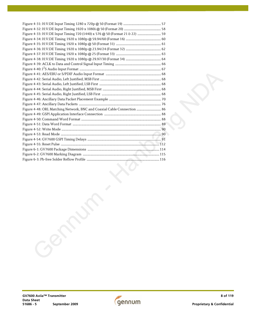
Figure 4-31: H:V:DE Input Timing 1280 x 720p @ 50 (Format 19) ................................................ 57
Figure 4-32: H:V:DE Input Timing 1920 x 1080i @ 50 (Format 20) ............................................... 58
Figure 4-33: H:V:DE Input Timing 720 (1440) x 576 @ 50 (Format 21 & 22) .............................. 59
Figure 4-34: H:V:DE Timing 1920 x 1080p @ 59.94/60 (Format 16) ............................................. 60
Figure 4-35: H:V:DE Timing 1920 x 1080p @ 50 (Format 31) ......................................................... 61
Figure 4-36: H:V:DE Timing 1920 x 1080p @ 23.94/24 (Format 32) ............................................. 62
Figure 4-37: H:V:DE Timing 1920 x 1080p @ 25 (Format 33) ......................................................... 63
Figure 4-38: H:V:DE Timing 1920 x 1080p @ 29.97/30 (Format 34) ............................................. 64
Figure 4-39: ACLK to Data and Control Signal Input Timing .......................................................... 66
Figure 4-40: I2S Audio Input Format ....................................................................................................... 67
Figure 4-41: AES/EBU or S/PDIF Audio Input Format ...................................................................... 68
Figure 4-42: Serial Audio, Left Justified, MSB First ............................................................................. 68
Figure 4-43: Serial Audio, Left Justified, LSB First .............................................................................. 68
Figure 4-44: Serial Audio, Right Justified, MSB First .......................................................................... 68
Figure 4-45: Serial Audio, Right Justified, LSB First ........................................................................... 68
Figure 4-46: Ancillary Data Packet Placement Example .................................................................. 70
Figure 4-47: Ancillary Data Packets ........................................................................................................ 76
Figure 4-48: ORL Matching Network, BNC and Coaxial Cable Connection ............................... 86
Figure 4-49: GSPI Application Interface Connection ........................................................................ 88
Figure 4-50: Command Word Format ..................................................................................................... 88
Figure 4-51: Data Word Format ................................................................................................................ 89
Figure 4-52: Write Mode .............................................................................................................................. 90
Figure 4-53: Read Mode ............................................................................................................................... 90
Figure 4-54: GV7600 GSPI Timing Delays ............................................................................................. 91
Figure 4-55: Reset Pulse .............................................................................................................................112
Figure 6-1: GV7600 Package Dimensions ...........................................................................................114
Figure 6-2: GV7600 Marking Diagram .................................................................................................115
Figure 6-3: Pb-free Solder Reflow Profile ............................................................................................116
GV7600 Aviia™ Transmitter
Data Sheet
51686 - 5
September 2009
8 of 119
Proprietary & Confidential
�




 2023年江西萍乡中考道德与法治真题及答案.doc
 2012年重庆南川中考生物真题及答案.doc
 2013年江西师范大学地理学综合及文艺理论基础考研真题.doc
 2020年四川甘孜小升初语文真题及答案I卷.doc
 2020年注册岩土工程师专业基础考试真题及答案.doc
 2023-2024学年福建省厦门市九年级上学期数学月考试题及答案.doc
 2021-2022学年辽宁省沈阳市大东区九年级上学期语文期末试题及答案.doc
 2022-2023学年北京东城区初三第一学期物理期末试卷及答案.doc
 2018上半年江西教师资格初中地理学科知识与教学能力真题及答案.doc
 2012年河北国家公务员申论考试真题及答案-省级.doc
 2020-2021学年江苏省扬州市江都区邵樊片九年级上学期数学第一次质量检测试题及答案.doc
 2022下半年黑龙江教师资格证中学综合素质真题及答案.doc