logo资料库

RTL2832U_Datasheet.pdf

第1页 / 共53页
第2页 / 共53页
第3页 / 共53页
第4页 / 共53页
第5页 / 共53页
第6页 / 共53页
第7页 / 共53页
第8页 / 共53页
资料共53页,剩余部分请下载后查看
General Description
Features
System Applications
Block Diagram
Pin Assignments
Green Package and Version Identification
Pin Descriptions
Functional Description
Analog-to-Digital Conversion (ADC)
Automatic Gain Control (AGC)
Digital Down Conversion
Resampler
Guard Interval Removal
Fast Fourier Transform (FFT)
Synchronization
Channel Estimation
Transmission Parameter Signal Decoder
Equalization
De-Interleaver, FEC Decoder, and Descrambler
Tuner Interface
Automatic Gain Control (AGC)
Register Name: loop_gain
Register Name: if_agc_min/if_agc_max/rf_agc_min/rf_agc_max
Register Name: Vtop
Register Name: Krf
Register Name: if_agc_val/rf_agc_val
ADC Input (Tuner Output)
Two-Wire Interface Between the Tuner and the RTL2832U
RTL2832U Internal Switching Regulator
Register Descriptions (General)
Analog to Digital Converter (ADC)
DC Cancellation and IQ Compensation
Digital Down Conversion (DDC)
Resampler
Co-Channel Interference Rejection
Impulse Noise Cancellation
Digital Automatic Gain Control (DAGC)
FFT Mode Detection
Timing Recovery/Carrier Recovery
Crystal
PID Filter
Register Descriptions (8051 System)
Demodulator Control Register (DEMOD_CTL, 0000h)
GPIO Related Registers (0001h~0008h)
GPIO Output Value Register (GPO, 0001h)
GPIO Input Value Register (GPI, 0002h)
GPIO Output Enable Register (GPOE, 0003h)
GPIO Direction Control Register (GPD, 0004h)
PAD Configuration Register for GPIO0~3 (GP_CFG0, 0007h)
PAD Configuration Register for GPIO4 (GP_CFG1, 0008h)
I2C Master Control Registers (0040h-0053h)
I2C Clock Register (I2CCR, 0040h-0043h)
I2C Master Control Register (I2CMCR, 0044h-0047h)
I2C Master SCL Timing Register (I2CMSTR, 0048h-004Bh)
I2C Master Status Register (I2CMSR, 004Ch-004Fh)
I2C Master FIFO Register (I2CMFR, 0050h-0053h)
Register Descriptions (USB Interface)
Introduction
Vendor Commands
SIE Control Register
USB System Control Register (USB_SYSCTL, 0000h)
Endpoint A Configuration Register (USB_EPA_CFG, 0144h)
Endpoint A Control Register (USB_EPA_CTL, 0148h)
Endpoint A Max Packet Size Register (USB_EPA_MAXPKT, 0158h)
Endpoint A FIFO Configuration Register (USB_EPA_FIFO_CFG, 01
Characteristics
Absolute Maximum Ratings
DC Characteristics
AC Characteristics
Crystal Conditions
Application Circuits
Mechanical Dimensions
Mechanical Dimensions Notes
Ordering Information
RTL2832U e N R O C DVB-T COFDM DEMODULATOR+USB 2.0 DATASHEET (CONFIDENTIAL: Development Partners Only) L e k T I A N L Rev. 1.4 01 November 2010 Track ID: JATR-2265-11 a lt F I D f o r V E 4 Realtek Semiconductor Corp. No. 2, Innovation Road II, Hsinchu Science Park, Hsinchu 300, Taiwan Tel.: +886-3-578-0211. Fax: +886-3-577-6047 www.realtek.com
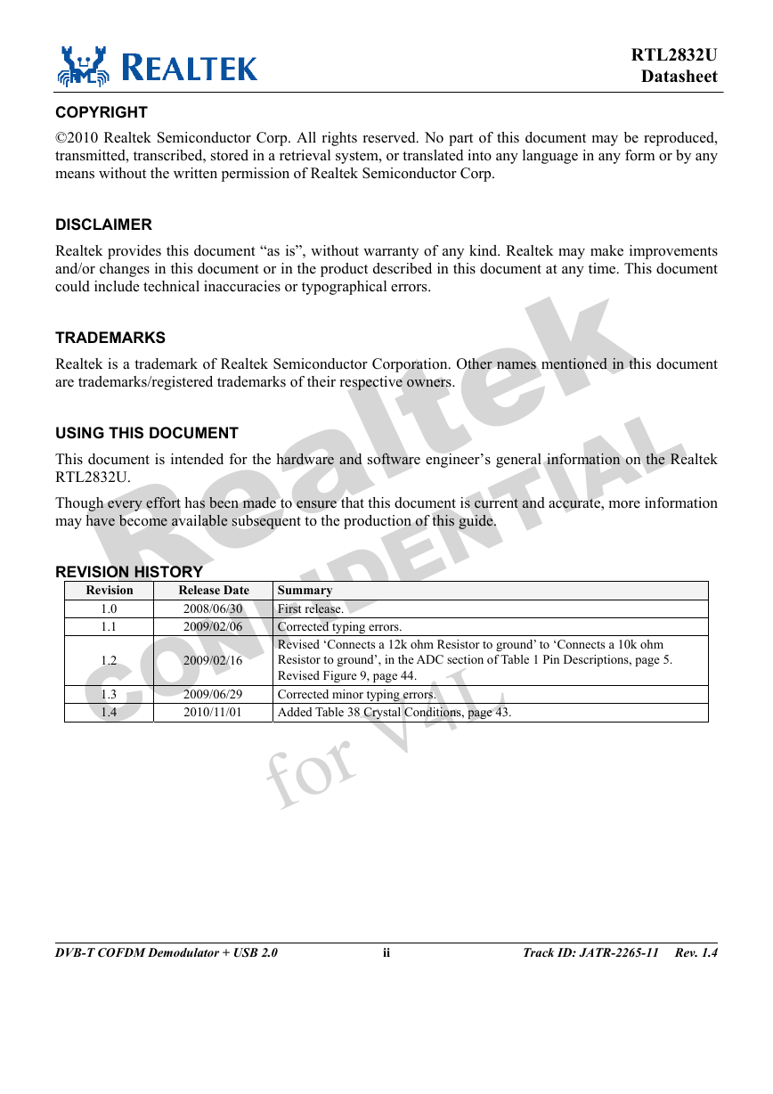
RTL2832U Datasheet COPYRIGHT ©2010 Realtek Semiconductor Corp. All rights reserved. No part of this document may be reproduced, transmitted, transcribed, stored in a retrieval system, or translated into any language in any form or by any means without the written permission of Realtek Semiconductor Corp. DISCLAIMER Realtek provides this document “as is”, without warranty of any kind. Realtek may make improvements and/or changes in this document or in the product described in this document at any time. This document could include technical inaccuracies or typographical errors. TRADEMARKS Realtek is a trademark of Realtek Semiconductor Corporation. Other names mentioned in this document are trademarks/registered trademarks of their respective owners. USING THIS DOCUMENT This document is intended for the hardware and software engineer’s general information on the Realtek RTL2832U. Though every effort has been made to ensure that this document is current and accurate, more information may have become available subsequent to the production of this guide. REVISION HISTORY k T I A e L Revision 1.0 1.1 1.2 1.3 1.4 C Release Date 2008/06/30 2009/02/06 2009/02/16 2009/06/29 2010/11/01 O Summary First release. Corrected typing errors. Revised ‘Connects a 12k ohm Resistor to ground’ to ‘Connects a 10k ohm Resistor to ground’, in the ADC section of Table 1 Pin Descriptions, page 5. Revised Figure 9, page 44. Corrected minor typing errors. Added Table 38 Crystal Conditions, page 43. R e N a lt F I D f o r V E 4 N L DVB-T COFDM Demodulator + USB 2.0 ii Track ID: JATR-2265-11 Rev. 1.4
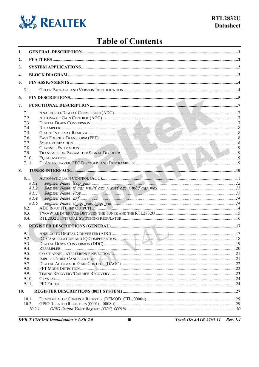
Table of Contents RTL2832U Datasheet 5.1. 6. 7. e L k T I A 1. GENERAL DESCRIPTION..............................................................................................................................................1 FEATURES.........................................................................................................................................................................2 2. SYSTEM APPLICATIONS...............................................................................................................................................2 3. 4. BLOCK DIAGRAM...........................................................................................................................................................3 PIN ASSIGNMENTS .........................................................................................................................................................4 5. GREEN PACKAGE AND VERSION IDENTIFICATION........................................................................................................4 PIN DESCRIPTIONS.........................................................................................................................................................5 FUNCTIONAL DESCRIPTION.......................................................................................................................................7 ANALOG-TO-DIGITAL CONVERSION (ADC).................................................................................................................7 7.1. AUTOMATIC GAIN CONTROL (AGC)............................................................................................................................7 7.2. DIGITAL DOWN CONVERSION ......................................................................................................................................7 7.3. RESAMPLER .................................................................................................................................................................8 7.4. GUARD INTERVAL REMOVAL.......................................................................................................................................8 7.5. FAST FOURIER TRANSFORM (FFT)...............................................................................................................................8 7.6. SYNCHRONIZATION......................................................................................................................................................8 7.7. CHANNEL ESTIMATION ................................................................................................................................................9 7.8. 7.9. TRANSMISSION PARAMETER SIGNAL DECODER...........................................................................................................9 EQUALIZATION ............................................................................................................................................................9 7.10. 7.11. DE-INTERLEAVER, FEC DECODER, AND DESCRAMBLER .............................................................................................9 TUNER INTERFACE......................................................................................................................................................10 AUTOMATIC GAIN CONTROL (AGC)..........................................................................................................................11 8.1.1. Register Name: loop_gain....................................................................................................................................12 8.1.2. Register Name: if_agc_min/if_agc_max/rf_agc_min/rf_agc_max .......................................................................13 8.1.3. Register Name: Vtop.............................................................................................................................................13 8.1.4. Register Name: Krf...............................................................................................................................................14 8.1.5. Register Name: if_agc_val/rf_agc_val.................................................................................................................14 ADC INPUT (TUNER OUTPUT) ...................................................................................................................................14 TWO-WIRE INTERFACE BETWEEN THE TUNER AND THE RTL2832U .........................................................................15 RTL2832U INTERNAL SWITCHING REGULATOR........................................................................................................16 9. REGISTER DESCRIPTIONS (GENERAL)..................................................................................................................17 ANALOG TO DIGITAL CONVERTER (ADC) .................................................................................................................17 9.1. DC CANCELLATION AND IQ COMPENSATION ............................................................................................................18 9.2. DIGITAL DOWN CONVERSION (DDC) ........................................................................................................................19 9.3. RESAMPLER ...............................................................................................................................................................20 9.4. CO-CHANNEL INTERFERENCE REJECTION..................................................................................................................21 9.5. IMPULSE NOISE CANCELLATION ................................................................................................................................21 9.6. DIGITAL AUTOMATIC GAIN CONTROL (DAGC) ........................................................................................................22 9.7. FFT MODE DETECTION..............................................................................................................................................22 9.8. TIMING RECOVERY/CARRIER RECOVERY ..................................................................................................................23 9.9. 9.10. CRYSTAL....................................................................................................................................................................24 PID FILTER ................................................................................................................................................................24 9.11. REGISTER DESCRIPTIONS (8051 SYSTEM) .......................................................................................................27 10.1. DEMODULATOR CONTROL REGISTER (DEMOD_CTL, 0000H) .................................................................................29 10.2. GPIO RELATED REGISTERS (0001H~0008H) .............................................................................................................29 GPIO Output Value Register (GPO, 0001h) ...................................................................................................30 a lt F I D f o r V e N R N L 8. 8.1. 8.2. 8.3. 8.4. 10. 10.2.1. E 4 O C DVB-T COFDM Demodulator + USB 2.0 iii Track ID: JATR-2265-11 Rev. 1.4
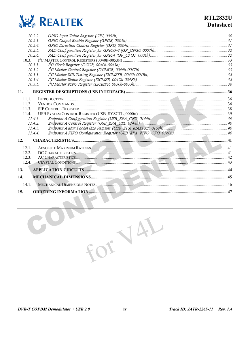
10.3. 10.2.2. 10.2.3. 10.2.4. 10.2.5. 10.2.6. 10.3.1. 10.3.2. 10.3.3. 10.3.4. 10.3.5. RTL2832U Datasheet GPIO Input Value Register (GPI, 0002h)........................................................................................................30 GPIO Output Enable Register (GPOE, 0003h)...............................................................................................31 GPIO Direction Control Register (GPD, 0004h) ............................................................................................31 PAD Configuration Register for GPIO0~3 (GP_CFG0, 0007h).....................................................................32 PAD Configuration Register for GPIO4 (GP_CFG1, 0008h).........................................................................32 I2C MASTER CONTROL REGISTERS (0040H-0053H) ...................................................................................................33 I2C Clock Register (I2CCR, 0040h-0043h)......................................................................................................33 I2C Master Control Register (I2CMCR, 0044h-0047h)...................................................................................33 I2C Master SCL Timing Register (I2CMSTR, 0048h-004Bh) ..........................................................................35 I2C Master Status Register (I2CMSR, 004Ch-004Fh) .....................................................................................35 I2C Master FIFO Register (I2CMFR, 0050h-0053h) ......................................................................................36 REGISTER DESCRIPTIONS (USB INTERFACE) ................................................................................................36 11.1. INTRODUCTION ..........................................................................................................................................................36 11.2. VENDOR COMMANDS.................................................................................................................................................36 11.3. SIE CONTROL REGISTER............................................................................................................................................38 11.4. USB SYSTEM CONTROL REGISTER (USB_SYSCTL, 0000H) ....................................................................................39 Endpoint A Configuration Register (USB_EPA_CFG, 0144h) .......................................................................39 Endpoint A Control Register (USB_EPA_CTL, 0148h) ..................................................................................40 Endpoint A Max Packet Size Register (USB_EPA_MAXPKT, 0158h) ............................................................40 Endpoint A FIFO Configuration Register (USB_EPA_FIFO_CFG, 0160h) ..................................................40 CHARACTERISTICS.................................................................................................................................................41 12.1. ABSOLUTE MAXIMUM RATINGS ................................................................................................................................41 12.2. DC CHARACTERISTICS...............................................................................................................................................41 12.3. AC CHARACTERISTICS...............................................................................................................................................42 12.4. CRYSTAL CONDITIONS...............................................................................................................................................43 APPLICATION CIRCUITS .......................................................................................................................................44 MECHANICAL DIMENSIONS.................................................................................................................................45 14.1. MECHANICAL DIMENSIONS NOTES ............................................................................................................................46 ORDERING INFORMATION...................................................................................................................................47 k T I A 11.4.1. 11.4.2. 11.4.3. 11.4.4. N e L a lt F I D f o r V E 4 L 11. 12. 13. 14. 15. C e N R O DVB-T COFDM Demodulator + USB 2.0 iv Track ID: JATR-2265-11 Rev. 1.4
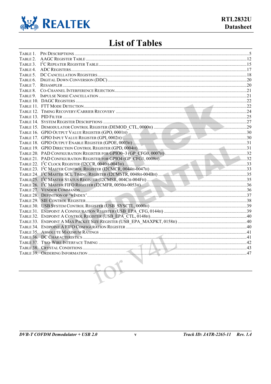
List of Tables RTL2832U Datasheet e L TABLE 1. PIN DESCRIPTIONS ........................................................................................................................................................5 TABLE 2. AAGC REGISTER TABLE ............................................................................................................................................12 TABLE 3. I2C REPEATER REGISTER TABLE.................................................................................................................................15 TABLE 4. ADC REGISTERS.........................................................................................................................................................17 TABLE 5. DC CANCELLATION REGISTERS..................................................................................................................................18 TABLE 6. DIGITAL DOWN CONVERSION (DDC) .........................................................................................................................20 TABLE 7. RESAMPLER ................................................................................................................................................................20 TABLE 8. CO-CHANNEL INTERFERENCE REJECTION...................................................................................................................21 TABLE 9. IMPULSE NOISE CANCELLATION.................................................................................................................................21 TABLE 10. DAGC REGISTERS .....................................................................................................................................................22 TABLE 11. FTT MODE DETECTION..............................................................................................................................................22 TABLE 12. TIMING RECOVERY/CARRIER RECOVERY ..................................................................................................................24 TABLE 13. PID FILTER ................................................................................................................................................................25 TABLE 14. SYSTEM REGISTER DESCRIPTIONS .............................................................................................................................27 TABLE 15. DEMODULATOR CONTROL REGISTER (DEMOD_CTL, 0000H) .................................................................................29 TABLE 16. GPIO OUTPUT VALUE REGISTER (GPO, 0001H) .......................................................................................................30 TABLE 17. GPIO INPUT VALUE REGISTER (GPI, 0002H) ............................................................................................................30 TABLE 18. GPIO OUTPUT ENABLE REGISTER (GPOE, 0003H) ...................................................................................................31 TABLE 19. GPIO DIRECTION CONTROL REGISTER (GPD, 0004H)...............................................................................................31 TABLE 20. PAD CONFIGURATION REGISTER FOR GPIO0~3 (GP_CFG0, 0007H) .......................................................................32 TABLE 21. PAD CONFIGURATION REGISTER FOR GPIO4 (GP_CFG1, 0008H)............................................................................32 TABLE 22. I2C CLOCK REGISTER (I2CCR, 0040H-0043H)...........................................................................................................33 TABLE 23. I2C MASTER CONTROL REGISTER (I2CMCR, 0044H-0047H) ....................................................................................33 TABLE 24. I2C MASTER SCL TIMING REGISTER (I2CMSTR, 0048H-004BH) .............................................................................35 TABLE 25. I2C MASTER STATUS REGISTER (I2CMSR, 004CH-004FH) .......................................................................................35 TABLE 26. I2C MASTER FIFO REGISTER (I2CMFR, 0050H-0053H)............................................................................................36 TABLE 27. VENDOR COMMANDS.................................................................................................................................................36 TABLE 28. DEFINITION OF ‘WINDEX’...........................................................................................................................................37 TABLE 29. SIE CONTROL REGISTER............................................................................................................................................38 TABLE 30. USB SYSTEM CONTROL REGISTER (USB_SYSCTL, 0000H) ....................................................................................39 TABLE 31. ENDPOINT A CONFIGURATION REGISTER (USB_EPA_CFG, 0144H) ........................................................................39 TABLE 32. ENDPOINT A CONTROL REGISTER (USB_EPA_CTL, 0148H)....................................................................................40 TABLE 33. ENDPOINT A MAX PACKET SIZE REGISTER (USB_EPA_MAXPKT, 0158H) ............................................................40 TABLE 34. ENDPOINT A FIFO CONFIGURATION REGISTER .........................................................................................................40 TABLE 35. ABSOLUTE MAXIMUM RATINGS ................................................................................................................................41 TABLE 36. DC CHARACTERISTICS...............................................................................................................................................41 TABLE 37. TWO-WIRE INTERFACE TIMING .................................................................................................................................42 TABLE 38. CRYSTAL CONDITIONS...............................................................................................................................................43 TABLE 39. ORDERING INFORMATION ..........................................................................................................................................47 k T I A e N R O a lt F I D f o r V E 4 N L C DVB-T COFDM Demodulator + USB 2.0 v Track ID: JATR-2265-11 Rev. 1.4
List of Figures RTL2832U Datasheet FIGURE 1. BLOCK DIAGRAM ........................................................................................................................................................3 FIGURE 2. PIN ASSIGNMENTS (48-PIN QFN)................................................................................................................................4 FIGURE 3. IF OR ZERO-IF TUNER INTERFACE.............................................................................................................................10 FIGURE 4. DELAYED AGC .........................................................................................................................................................11 FIGURE 5. TWO-WIRE INTERFACE BETWEEN THE TUNER AND RTL2832U ................................................................................15 FIGURE 6. INTERNAL SWITCHING REGULATOR LAYOUT ............................................................................................................16 FIGURE 7. PID FILTER FUNCTION OF THE RTL2832U................................................................................................................24 FIGURE 8. TWO-WIRE INTERFACE TIMING DIAGRAM ................................................................................................................42 FIGURE 9. APPLICATION CIRCUITS.............................................................................................................................................44 e N R O C a lt F I D f o r V E N L 4 e k T I A L DVB-T COFDM Demodulator + USB 2.0 vi Track ID: JATR-2265-11 Rev. 1.4
RTL2832U Datasheet 1. General Description The RTL2832U is a high-performance DVB-T COFDM demodulator that supports a USB 2.0 interface. The RTL2832U complies with NorDig Unified 1.0.3, D-Book 5.0, and EN300 744 (ETSI Specification). It supports 2K or 8K mode with 6, 7, and 8MHz bandwidth. Modulation parameters, e.g., code rate, and guard interval, are automatically detected. The RTL2832U supports tuners at IF (Intermediate Frequency, 36.125MHz), low-IF (4.57MHz), or Zero-IF output using a 28.8MHz crystal. Embedded with an advanced ADC (Analog-to-Digital Converter), the RTL2832U features high stability in portable reception. The state-of-the-art RTL2832U features Realtek proprietary algorithms (patent-pending), including superior channel estimation, co-channel interface rejection, long echo channel reception, and impulse noise cancellation, and provides an ideal solution for a wide range of applications for PC-TV, such as USB dongle and MiniCard/USB, and embedded system via USB interface. e k T I A L R O C e N a lt F I D f o r V E 4 N L DVB-T COFDM Demodulator + USB 2.0 1 Track ID: JATR-2265-11 Rev. 1.4
2. Features RTL2832U Datasheet COFDM complying with Nordig Unified Delayed AGC with programmable 1.0.3, D-book 5.0, and ETSI 300-744 Take-Over Point (TOP) Supports multiple IF frequencies (4.57MHz or 36.167MHz) and spectrum inversion Supports Zero-IF input Single low-cost crystal for clock generation Automatic transmission mode and guard NEC, Sony, SIRC, RC-5 protocol Superior performance with pre/post/long external EEPROM 7-bit ADC for RF signals level measurement Hardware MPEG-2 PID filters Infra-red port for remote control and wake-up, protocols supported are Microsoft RC6 protocol e k T I A L Eight general purpose I/O ports USB 2.0 Interface Supports USB Full/High speed Configurable vendor information via Passes USB-IF certification Signal 3.3V external power is required 48-pin QFN (6x6 mm2) Green Package N L (±100ppm) interval detection R O C Impulse noise cancellation circuits Automatic carrier recovery over a wide range offset (±800KHz) echo profiles Embedded adjacent and co-channel interference rejection circuit 3. System Applications e N a lt F I D f o r V E 4 Portable DTV device USB dongle MiniCard DVB-T COFDM Demodulator + USB 2.0 2 Track ID: JATR-2265-11 Rev. 1.4
分享到:
收藏