TW8816 - LCD Flat Panel Processor with built-in MCU,
NTSC/PAL/SECAM Decoder, T-CON and Analog RGB Support
Techwell Confidential. Information may change
without notice
Disclaimer
This document provides technical information for the user. Techwell Inc. reserves the right to modify the
information in this document as necessary. The customer should make sure that they have the most recent data
sheet version. Techwell Inc. holds no responsibility for any errors that may appear in this document. Customers
should take appropriate action to ensure their use of the products does not infringe upon any patents. Techwell
Inc. respects valid patent rights of third parties and does not infringe upon or assist others to infringe upon such
rights.
TECHWELL, INC.
1
REV. A
05/15/2008
www.DataSheet.in�
TW8816
TFT Flat Panel Processor with Video Decoder, MCU and TCON
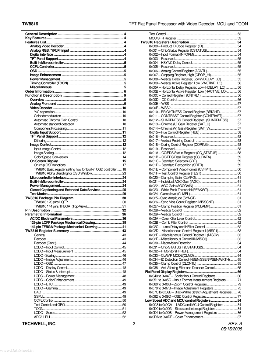
General Description ........................................................................ 4
Key Features .................................................................................... 4
Features List..................................................................................... 4
Analog Video Decoder...........................................................................4
Analog RGB / YPbPr input ....................................................................4
Digital interface ........................................................................................4
TFT Panel Support..................................................................................4
Built-in Microcontroller...........................................................................5
CCFL Controller.......................................................................................5
OSD............................................................................................................5
Image Enhancement ..............................................................................5
Power Management................................................................................5
Timing Controller (TCON)......................................................................5
Miscellaneous..........................................................................................5
Order Information ............................................................................ 6
Functional Description ................................................................... 9
Overview ...................................................................................................9
Analog Front-end ....................................................................................9
Video Decoder .......................................................................................10
Y/C separation ....................................................................................10
Color demodulation ............................................................................10
Automatic Chroma Gain Control.......................................................10
Automatic standard detection............................................................10
Component Processing .....................................................................11
Digital Input Support.............................................................................11
TFT Panel Support................................................................................12
Dithering...............................................................................................12
Image Control.........................................................................................12
Input Image Control............................................................................12
Image Scaling .....................................................................................12
Color Space Conversion....................................................................14
On Screen Display ................................................................................15
On chip OSD functions.......................................................................17
TW8816 Basic register setting flow for Built-in OSD controller.......18
TW8816 Alpha Blending for OSD Window......................................23
Microcontroller Interface......................................................................24
Built-in Microcontroller.........................................................................24
Power Management..............................................................................24
Closed Captioning and Extended Data Services...........................25
Test Modes .............................................................................................29
TW8816 Package Pin Diagram .................................................... 30
TW8816 128 pins LQFP....................................................................30
TW8816 144 pins TFBGA (Top-View)............................................31
Pin Description .............................................................................. 32
Parametric Information................................................................. 36
AC/DC Electrical Parameters..............................................................36
128-pin LQFP Package Mechanical Drawing..................................39
144-pin TFBGA Package Mechanical Drawing...............................41
TW8816 Register Summary ......................................................... 43
General................................................................................................43
Decoder...............................................................................................43
Decoder (Cont.)...................................................................................44
LCDC – Input Control.........................................................................45
LCDC – Input Measurement .............................................................45
LCDC - Scaling...................................................................................46
LCDC – Image Adjustment................................................................46
LCDC – OSD......................................................................................47
LCDC – Display Control.....................................................................48
LCDC – Status & Interrupt .................................................................48
LCDC – Power Management............................................................48
LCDC – Color Enhancement ............................................................49
LCDC – ETC.......................................................................................49
LCDC – Gamma ................................................................................49
DAC .....................................................................................................49
SSPLL..................................................................................................49
CCFL Control......................................................................................50
Test Control and GPO........................................................................50
TCON...................................................................................................51
LCDC – Sense....................................................................................52
ADC/LLPLL.........................................................................................52
TECHWELL, INC.
2
Test Control.........................................................................................53
MCU SFR Register ............................................................................53
TW8816 Registers Description.................................................... 54
0x000 – Product ID Code Register (ID)...........................................54
0x001 – Chip Status Register (CSTATUS)......................................54
0x002 – Input Format (INFORM)......................................................54
0x003 – Reserved ..............................................................................55
0x004 – HSYNC Delay Control.........................................................55
0x005 – Reserved ..............................................................................55
0x006 – Analog Control Register (ACNTL)......................................55
0x007 – Cropping Register, High (CROP_HI).................................55
0x008 – Vertical Delay Register, Low (VDELAY_LO) ....................55
0x009 – Vertical Active Register, Low (VACTIVE_LO)...................56
0x00A – Horizontal Delay Register, Low (HDELAY_LO)...............56
0x00B – Horizontal Active Register, Low (HACTIVE_LO).............56
0x00C – Control Register I (CNTRL1)..............................................56
0x00D – CC Control...........................................................................56
0x00E – WSS1...................................................................................57
0x00F – WSS2 ...................................................................................57
0x010 – BRIGHTNESS Control Register (BRIGHT)......................57
0x011 – CONTRAST Control Register (CONTRAST)...................57
0x012 – SHARPNESS Control Register I (SHARPNESS) ...........57
0x013 – Chroma (U) Gain Register (SAT_U)..................................57
0x014 – Chroma (V) Gain Register (SAT_V) ..................................57
0x015 – Hue Control Register (HUE) ...............................................58
0x016 – Reserved ..............................................................................58
0x017 – Vertical Peaking Control I....................................................58
0x018 – Coring Control Register (CORING)....................................58
0x019 – Reserved ..............................................................................58
0x01A – CC/EDS Status Register (CC_STATUS).........................58
0x01B – CC/EDS Data Register (CC_DATA).................................59
0x01C – Standard Selection (SDT) ..................................................59
0x01D – Standard Recognition (SDTR)...........................................59
0x01E – Component Video Format (CVFMT).................................60
0x01F – Test Control Register (TEST).............................................60
0x020 – Clamping Gain (CLMPG)....................................................61
0x021 – Individual AGC Gain (IAGC)...............................................61
0x022 – AGC Gain (AGCGAIN).......................................................61
0x023 – White Peak Threshold (PEAKWT).....................................61
0x024– Clamp level (CLMPL)...........................................................61
0x025– Sync Amplitude (SYNCT)....................................................61
0x026 – Sync Miss Count Register (MISSCNT) .............................61
0x027 – Clamp Position Register (PCLAMP)..................................61
0x028 – Vertical Control I ...................................................................62
0x029 – Vertical Control II ..................................................................62
0x02A – Color Killer Level Control.....................................................62
0x02B – Comb Filter Control .............................................................62
0x02C – Luma Delay and HFilter Control ........................................62
0x02D – Miscellaneous Control Register I (MISC1)........................63
0x02E – Miscellaneous Control Register II (MISC2).......................63
0x02F – Miscellaneous Control III (MISC3)......................................63
0x030 – Macrovision Detection.........................................................64
0x031 – Chip STATUS II (CSTATUS2)...........................................64
0x032 – H Monitor (HFREF)..............................................................64
0x033 – CLAMP MODE(CLMD)......................................................64
0x034 – ID Detection Control (NSEN/SSEN/PSEN/WKTH).........65
0x035 – Clamp Control (CLCNTL) ...................................................65
0x038 – Anti-Aliasing Filter and Decoder Control............................65
Flat Panel Display Registers...............................................................66
0x040 to 0x04F – Scaler Input Control Registers ...........................66
0x051 to 0x05C – Input Format Measurement Registers ..............71
0x060 to 0x06B – Zoom Control Registers......................................73
0x070 to 0x07B – Image Adjustment Registers ..............................75
0x07C to 0x08B – Black/White Stretch Adjustment Registers.......76
0x092 to 0x09D – OSD Control Registers .......................................77
Low Speed ADC and MCU control Registers.................................84
0x0C8 to 0x0CA – LADC and MCU Control Registers .................84
0x0D0 to 0x0D3 – Status and Interrupt Registers...........................84
0x0D4 to 0x0D8 – Power Management Registers .........................86
0x0DA to 0x0DF – Color Enhancement...........................................87
REV. A
05/15/2008
www.DataSheet.in�
TW8816
TFT Flat Panel Processor with Video Decoder, MCU and TCON
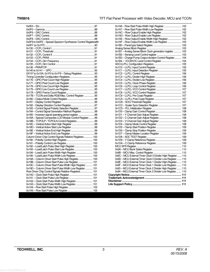
0x0E0 – Etc.........................................................................................87
0x0F0 – Gamma.................................................................................88
0x0F6 – DAC Control.........................................................................88
0x0F7 – DAC Control.........................................................................88
0x0F8 – DAC Control.........................................................................88
0x0F9 to 0x0FE – Spread Spectum Synthesizer Control Registers89
0x0FF (or 0x1FF)................................................................................90
0x130 – CCFL Control I .....................................................................91
0x131 – CCFL Threshold ..................................................................91
0x132 – CCFL Control II ....................................................................91
0x133 – CCFL PWM..........................................................................91
0x134 – CCFL Dim Frequency.........................................................91
0x135 – CCFL Dim Control ...............................................................91
0x136 – PWMTOP.............................................................................91
0x140 to 0x141 – GPO .....................................................................92
0X157 to 0x15A, 0x1F0 to 0x1F9 – Debug Registers ....................93
Timing Controller Configuration Registers........................................95
0x176 – GPIO Pixel Count High Register ........................................95
0x177 – GPIO Pixel Count Low Register.........................................95
0x178 – GPIO Line Count High Register.........................................95
0x179 – GPIO Line Count Low Register..........................................95
0x17A – GPIO Frame Count Register..............................................95
0x17B – TCON and Delta RGB Misc. Control Register .................95
0x180 – Output Mode Control Register............................................96
0x181 – Display Control Register......................................................96
0x182 – Display Direction Control Register......................................97
0x183 – Control Signal Polarity Selection Register..........................97
0x184 – Control Signal Generation Method Register......................98
0x185 – Inversion signal operating period register...........................98
0x18A – Special Companies LCD Module Control Register..........99
0x18B – TCPOLP / TCPOLN Control Registers.............................99
0x18C – Vertical Active Start High Register.....................................99
0x18D – Vertical Active Start Low Register......................................99
0x18E – Vertical Active End High Register ......................................99
0x18F – Vertical Active End Low Register .......................................99
Column Driver Chip Control Signals Relative Registers .............. 100
0x190 – Polarity Control High Register.......................................... 100
0x191 – Polarity Control Low Register........................................... 100
0x192 – Load/Latch Pulse Start High Register............................. 100
0x193 – Load/Latch Pulse Start Low Register.............................. 100
0x194 – Load/Latch Pulse Width High Register........................... 100
0x195 – Load/Latch Pulse Width Low Register............................ 100
0x19A – Column Driver Start Pulse High Register....................... 100
0x19B – Column Driver Start Pulse Low Register........................ 101
0x19C – Column Driver Start Pulse Width High Register............ 101
0x19D – Column Driver Start Pulse Width Low Register ............ 101
Row Driver Chip Control Signals Relative Registers.................... 101
0x1A0 – Clock Start Pulse High Register...................................... 101
0x1A1 – Clock Start Pulse Low Register....................................... 101
0x1A2 – Clock Start Pulse Width High Register........................... 101
0x1A3 – Clock Start Pulse Width Low Register............................ 101
0x1A4 – Row Start Pulse High Register........................................ 102
0x1A5 – Row Start Pulse Low Register ........................................ 102
TECHWELL, INC.
3
0x1A6 – Row Start Pulse Width High Register............................. 102
0x1A7 – Row Start Pulse Width Low Register ............................. 102
0x1AC – Row Output Enable High Register................................. 102
0x1AD – Row Output Enable Low Register.................................. 102
0x1AE – Row Output Enable Width High Register...................... 102
0x1AF – Row Output Enable Width Low Register....................... 103
0x1B0 – Panel type Select Register............................................... 103
Analog Sense Block Register......................................................... 103
0x1B1 – Analog Sense Block Clock generation register ............. 103
0x1B2 – Sensing Level Control register ........................................ 103
0x1B3 – Charge Pump Output duration Control Register........... 104
0x1B4 – VCOM DC Level Control Register................................. 104
ADC/LLPLL Configuration Registers............................................. 105
0x1C0 – LLPLL Input Control Register.......................................... 105
0x1C1 – LLPLL Input Detection Register...................................... 105
0x1C2 – LLPLL Control Register ................................................... 106
0x1C3 – LLPLL Divider High Register........................................... 106
0x1C4 – LLPLL Divider Low Register............................................ 106
0x1C5 – LLPLL Clock Phase Register.......................................... 106
0x1C6 – LLPLL Loop Control Register.......................................... 106
0x1C7 – LLPLL VCO Control Register.......................................... 107
0x1C8 – LLPLL VCO Control Register.......................................... 107
0x1C9 – LLPLL Pre Coast Register .............................................. 107
0x1CA – LLPLL Post Coast Register............................................ 107
0x1CB – SOG Threshold Register ................................................ 107
0x1CC – Scaler Sync Selection Register...................................... 107
0x1CD – PLL Initialization Register................................................ 108
0x1D0 – Clamp Gain Control Register.......................................... 108
0x1D1 – Y Channel Gain Adjust Register..................................... 108
0x1D2 – C Channel Gain Adjust Register..................................... 108
0x1D3 – V Channel Gain Adjust Register..................................... 108
0x1D4 – Clamp Mode Control Register ........................................ 108
0x1D5 – Clamp Start Position Register......................................... 109
0x1D6 – Clamp Stop Position Register......................................... 109
0x1D7 – Clamp Master Location Register .................................... 109
0x1D8 – ADC TEST Register ........................................................ 109
0x1D9 – Y Clamp Reference Register.......................................... 109
0x1DA – C Clamp Reference Register ......................................... 109
MCU SFR Register ......................................................................... 110
0x9A – MCU Bank Select Register................................................ 110
0x9B – MCU Misc. Control Register.............................................. 110
0x9C – MCU External Timer Clock 0 Divider High Register ....... 110
0x9D – MCU External Timer Clock 0 Divider Low Register........ 110
0x9E – MCU External Timer Clock 1 Divider High Register........ 110
0x9F – MCU External Timer Clock 1 Divider Low Register......... 110
0x93 – MCU External Timer Clock 2 Divider High Register........ 110
0x94 – MCU External Timer Clock 2 Divider Low Register......... 110
Copyright Notice.......................................................................... 111
Trademark Acknowledgment .................................................... 111
Disclaimer..................................................................................... 111
Life Support Policy...................................................................... 111
REV. A
05/15/2008
www.DataSheet.in�
TW8816
TFT Flat Panel Processor with Video Decoder, MCU and TCON
General Description
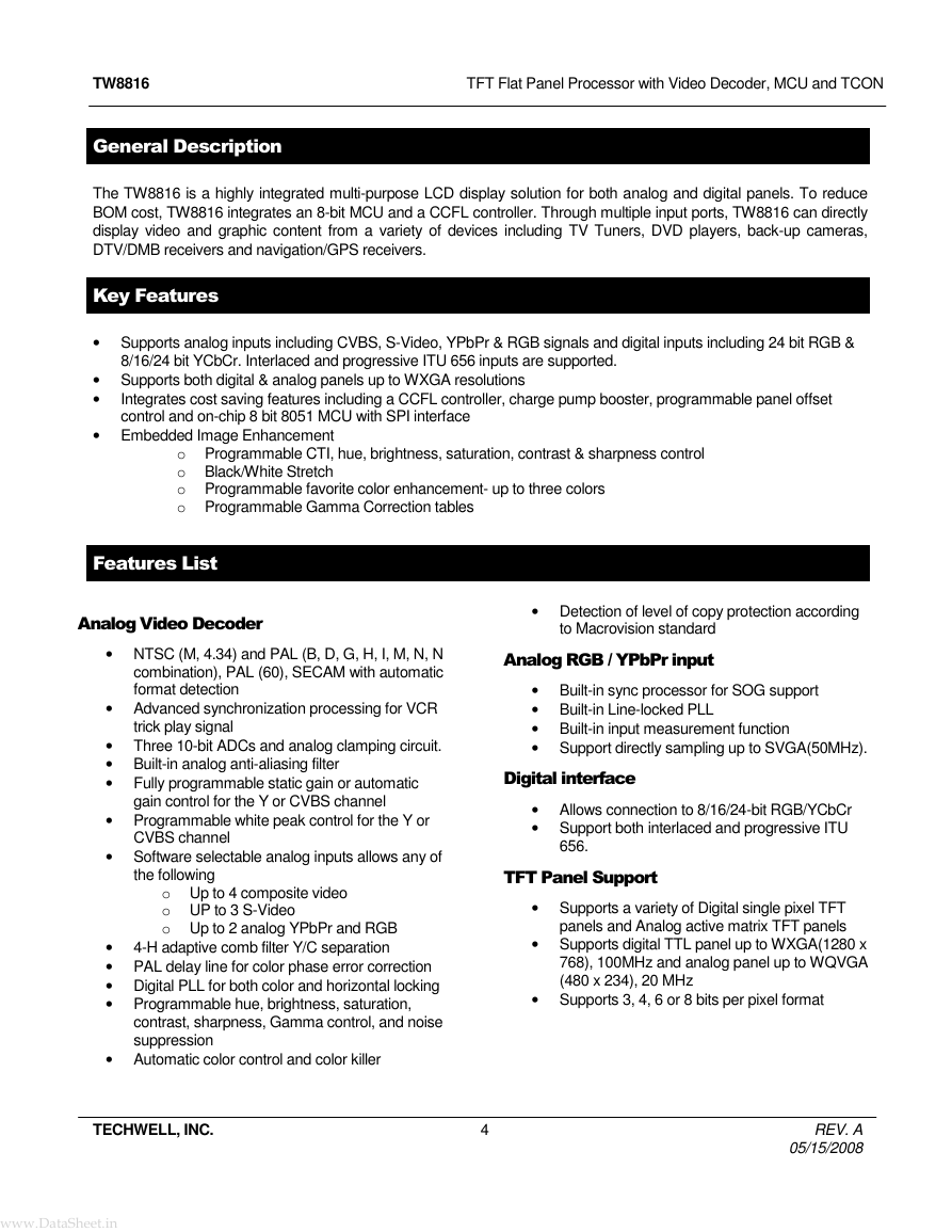
The TW8816 is a highly integrated multi-purpose LCD display solution for both analog and digital panels. To reduce
BOM cost, TW8816 integrates an 8-bit MCU and a CCFL controller. Through multiple input ports, TW8816 can directly
display video and graphic content from a variety of devices including TV Tuners, DVD players, back-up cameras,
DTV/DMB receivers and navigation/GPS receivers.
Key Features
• Supports analog inputs including CVBS, S-Video, YPbPr & RGB signals and digital inputs including 24 bit RGB &
8/16/24 bit YCbCr. Interlaced and progressive ITU 656 inputs are supported.
• Supports both digital & analog panels up to WXGA resolutions
•
Integrates cost saving features including a CCFL controller, charge pump booster, programmable panel offset
control and on-chip 8 bit 8051 MCU with SPI interface
• Embedded Image Enhancement
o Programmable CTI, hue, brightness, saturation, contrast & sharpness control
o Black/White Stretch
o Programmable favorite color enhancement- up to three colors
o Programmable Gamma Correction tables
Features List
Analog Video Decoder
• NTSC (M, 4.34) and PAL (B, D, G, H, I, M, N, N
combination), PAL (60), SECAM with automatic
format detection
• Advanced synchronization processing for VCR
trick play signal
• Three 10-bit ADCs and analog clamping circuit.
• Built-in analog anti-aliasing filter
• Fully programmable static gain or automatic
gain control for the Y or CVBS channel
• Programmable white peak control for the Y or
CVBS channel
• Software selectable analog inputs allows any of
the following
o Up to 4 composite video
o UP to 3 S-Video
o Up to 2 analog YPbPr and RGB
• 4-H adaptive comb filter Y/C separation
• PAL delay line for color phase error correction
• Digital PLL for both color and horizontal locking
• Programmable hue, brightness, saturation,
contrast, sharpness, Gamma control, and noise
suppression
• Automatic color control and color killer
• Detection of level of copy protection according
to Macrovision standard
Analog RGB / YPbPr input
• Built-in sync processor for SOG support
• Built-in Line-locked PLL
• Built-in input measurement function
• Support directly sampling up to SVGA(50MHz).
Digital interface
• Allows connection to 8/16/24-bit RGB/YCbCr
• Support both interlaced and progressive ITU
656.
TFT Panel Support
• Supports a variety of Digital single pixel TFT
panels and Analog active matrix TFT panels
• Supports digital TTL panel up to WXGA(1280 x
768), 100MHz and analog panel up to WQVGA
(480 x 234), 20 MHz
• Supports 3, 4, 6 or 8 bits per pixel format
TECHWELL, INC.
4
REV. A
05/15/2008
www.DataSheet.in�
TW8816
TFT Flat Panel Processor with Video Decoder, MCU and TCON
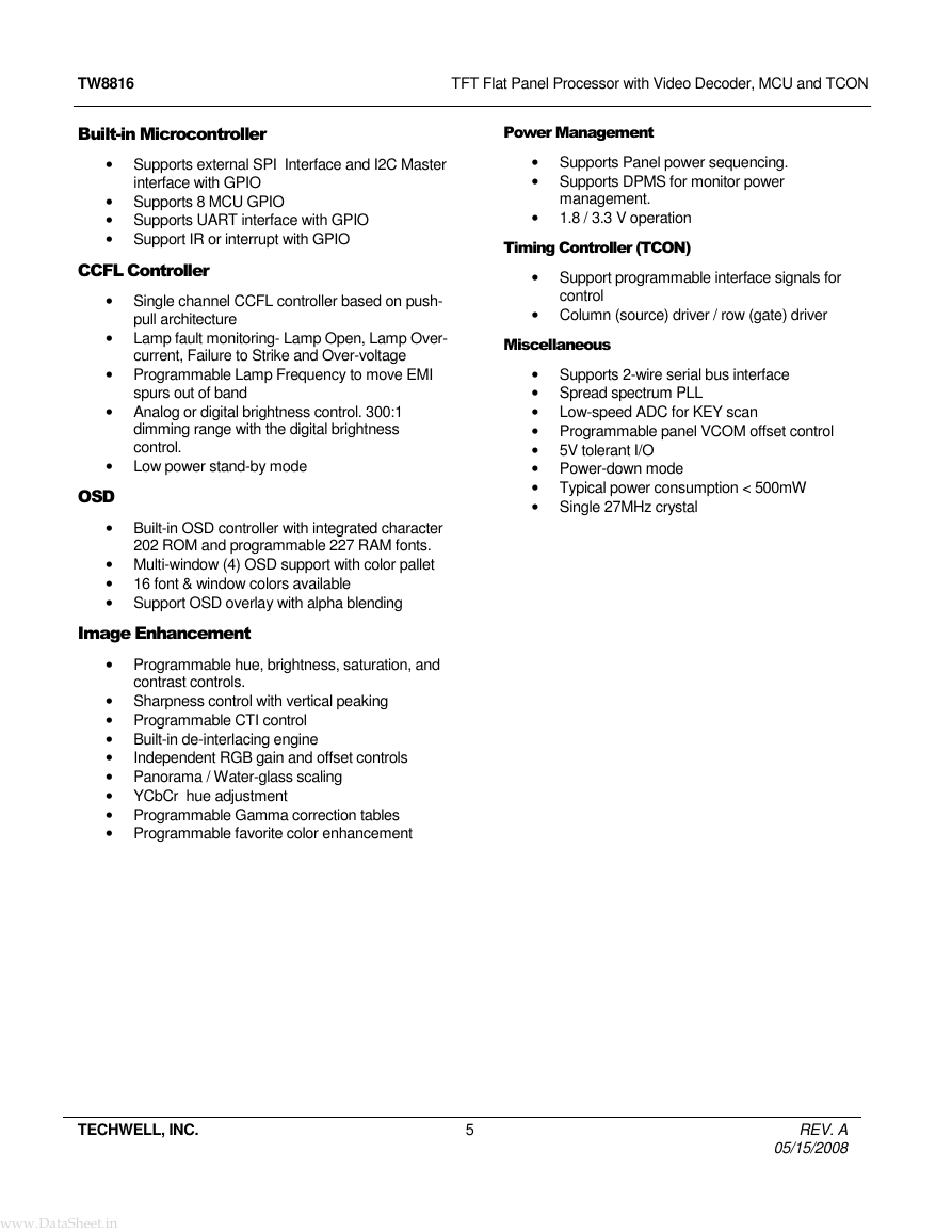
Built-in Microcontroller
Power Management
• Supports external SPI Interface and I2C Master
interface with GPIO
• Supports 8 MCU GPIO
• Supports UART interface with GPIO
• Support IR or interrupt with GPIO
• Supports Panel power sequencing.
• Supports DPMS for monitor power
management.
• 1.8 / 3.3 V operation
Timing Controller (TCON)
• Support programmable interface signals for
control
• Column (source) driver / row (gate) driver
Miscellaneous
• Supports 2-wire serial bus interface
• Spread spectrum PLL
• Low-speed ADC for KEY scan
• Programmable panel VCOM offset control
• 5V tolerant I/O
• Power-down mode
• Typical power consumption < 500mW
• Single 27MHz crystal
CCFL Controller
• Single channel CCFL controller based on push-
pull architecture
• Lamp fault monitoring- Lamp Open, Lamp Over-
current, Failure to Strike and Over-voltage
• Programmable Lamp Frequency to move EMI
spurs out of band
• Analog or digital brightness control. 300:1
dimming range with the digital brightness
control.
• Low power stand-by mode
OSD
• Built-in OSD controller with integrated character
202 ROM and programmable 227 RAM fonts.
• Multi-window (4) OSD support with color pallet
• 16 font & window colors available
• Support OSD overlay with alpha blending
Image Enhancement
• Programmable hue, brightness, saturation, and
contrast controls.
Independent RGB gain and offset controls
• Sharpness control with vertical peaking
• Programmable CTI control
• Built-in de-interlacing engine
•
• Panorama / Water-glass scaling
• YCbCr hue adjustment
• Programmable Gamma correction tables
• Programmable favorite color enhancement
TECHWELL, INC.
5
REV. A
05/15/2008
www.DataSheet.in�
TW8816
TFT Flat Panel Processor with Video Decoder, MCU and TCON
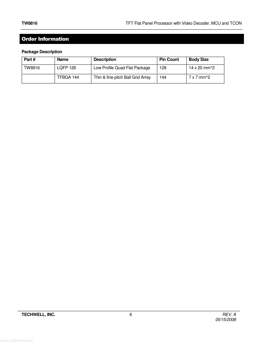
Order Information
Package Description
Part #
Name
Description
Pin Count
Body Size
TW8816
LQFP 128
Low Profile Quad Flat Package
128
14 x 20 mm^2
TFBGA 144
Thin & fine-pitch Ball Grid Array
144
7 x 7 mm^2
TECHWELL, INC.
6
REV. A
05/15/2008
www.DataSheet.in�
TW8816
TFT Flat Panel Processor with Video Decoder, MCU and TCON
n
o
i
t
l
a
u
d
o
m
e
D
r
e
t
l
i
F
b
m
o
C
d
n
E
t
n
o
r
F
g
o
a
n
A
X
3
l
a
m
o
r
h
C
e
v
i
t
p
a
d
A
H
4
c
n
y
S
r
o
s
s
e
c
o
r
P
data
OSD
Alpha Blending
t
n
e
m
e
c
n
a
h
n
E
e
g
a
m
I
r
e
h
t
i
D
/
a
m
m
a
G
i
g
n
s
s
e
c
o
r
P
V
U
Y
X
U
M
x
i
r
t
a
M
l
r
o
o
C
s
r
e
f
f
u
B
e
n
L
i
r
e
c
a
l
r
e
n
e
D
t
i
l
/
r
e
a
c
S
c
n
y
S
r
o
s
s
e
c
o
r
P
PLL
pixel clock
hsync
Input Format
Measurement
Registers
Host
Interface
F
/
I
V
T
D
t
r
o
a
r
e
n
e
G
g
n
m
T
i
i
l
e
n
a
P
2 Wire
Serial Bus
MCU
Low-speed
ADC
Spread
Spectrum
PLL
CCFL
controller
SPI Interface
Figure 1 TW8816 Flat Panel TV/Monitor controller functional block diagram
N
O
C
T
TCON signals
X
U
M
DAC
FPR[7:0]
FPG[7:0]
FPB[7:0]
FPVS
FPHS
FPDE
FPCLK
FPPWC
FPBIAS
ROUT
GOUT
BOUT
MC SDA
MC SIA
MC SCL
MCU EN
P2.0~P2.7
MCU SDA
MCU SCL
SPI_DO
SPI_DI
SPI_CSN
SPI_CLKO
X
U
M
X
U
M
X
U
M
YIN0
YIN1
YIN2
YIN3
YOUT
CIN0
CIN1
CIN2
VIN0
VIN1
SOYIN
VSYNC
HSYNC
DTVCLK
DTVVS
DTVHS
DTVDE
DTVD[23:0]
LADIN0
LADIN1
TECHWELL, INC.
7
REV. A
05/15/2008
www.DataSheet.in�
TW8816
TFT Flat Panel Processor with Video Decoder, MCU and TCON
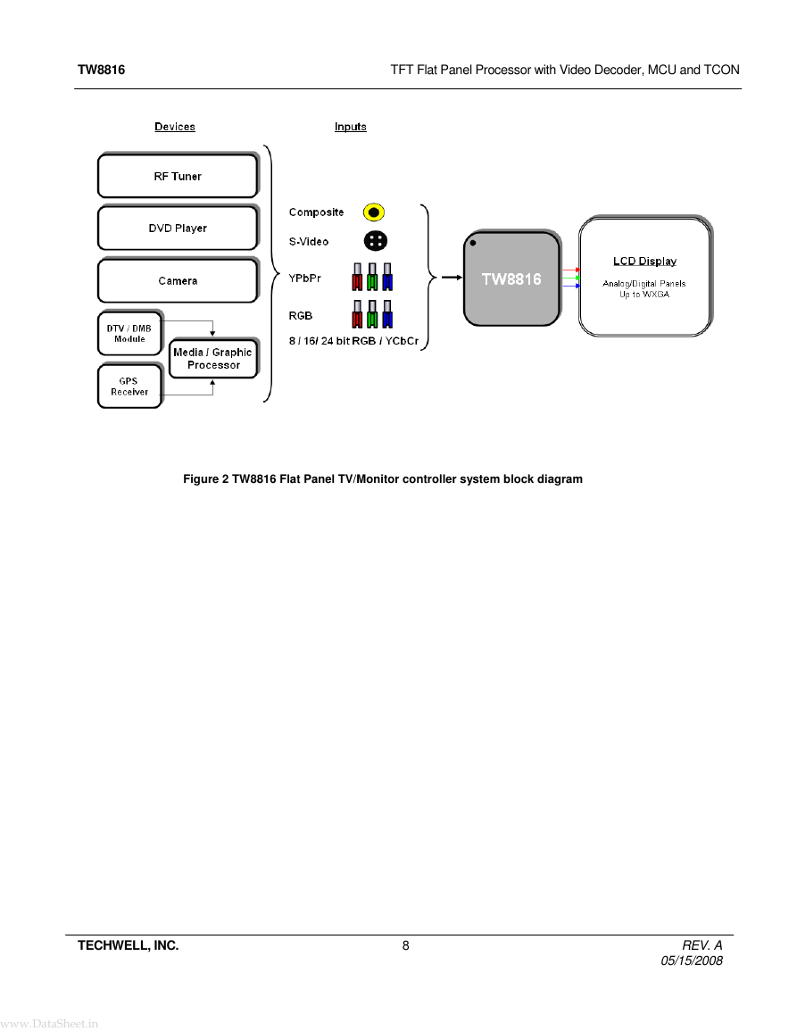
Figure 2 TW8816 Flat Panel TV/Monitor controller system block diagram
TECHWELL, INC.
8
REV. A
05/15/2008
www.DataSheet.in�



 2023年江西萍乡中考道德与法治真题及答案.doc
 2012年重庆南川中考生物真题及答案.doc
 2013年江西师范大学地理学综合及文艺理论基础考研真题.doc
 2020年四川甘孜小升初语文真题及答案I卷.doc
 2020年注册岩土工程师专业基础考试真题及答案.doc
 2023-2024学年福建省厦门市九年级上学期数学月考试题及答案.doc
 2021-2022学年辽宁省沈阳市大东区九年级上学期语文期末试题及答案.doc
 2022-2023学年北京东城区初三第一学期物理期末试卷及答案.doc
 2018上半年江西教师资格初中地理学科知识与教学能力真题及答案.doc
 2012年河北国家公务员申论考试真题及答案-省级.doc
 2020-2021学年江苏省扬州市江都区邵樊片九年级上学期数学第一次质量检测试题及答案.doc
 2022下半年黑龙江教师资格证中学综合素质真题及答案.doc